EP1018288B1 - Autoradioanlage - Google Patents
Autoradioanlage Download PDFInfo
- Publication number
- EP1018288B1 EP1018288B1 EP98928089A EP98928089A EP1018288B1 EP 1018288 B1 EP1018288 B1 EP 1018288B1 EP 98928089 A EP98928089 A EP 98928089A EP 98928089 A EP98928089 A EP 98928089A EP 1018288 B1 EP1018288 B1 EP 1018288B1
- Authority
- EP
- European Patent Office
- Prior art keywords
- loudspeakers
- car radio
- speakers
- speaker
- switch
- Prior art date
- Legal status (The legal status is an assumption and is not a legal conclusion. Google has not performed a legal analysis and makes no representation as to the accuracy of the status listed.)
- Expired - Lifetime
Links
- 238000009434 installation Methods 0.000 claims 9
- 230000004048 modification Effects 0.000 description 3
- 238000012986 modification Methods 0.000 description 3
- 239000012528 membrane Substances 0.000 description 1
- 230000005236 sound signal Effects 0.000 description 1
Images

Classifications
-
- H—ELECTRICITY
- H04—ELECTRIC COMMUNICATION TECHNIQUE
- H04R—LOUDSPEAKERS, MICROPHONES, GRAMOPHONE PICK-UPS OR LIKE ACOUSTIC ELECTROMECHANICAL TRANSDUCERS; DEAF-AID SETS; PUBLIC ADDRESS SYSTEMS
- H04R5/00—Stereophonic arrangements
- H04R5/04—Circuit arrangements, e.g. for selective connection of amplifier inputs/outputs to loudspeakers, for loudspeaker detection, or for adaptation of settings to personal preferences or hearing impairments
-
- H—ELECTRICITY
- H04—ELECTRIC COMMUNICATION TECHNIQUE
- H04R—LOUDSPEAKERS, MICROPHONES, GRAMOPHONE PICK-UPS OR LIKE ACOUSTIC ELECTROMECHANICAL TRANSDUCERS; DEAF-AID SETS; PUBLIC ADDRESS SYSTEMS
- H04R3/00—Circuits for transducers, loudspeakers or microphones
- H04R3/12—Circuits for transducers, loudspeakers or microphones for distributing signals to two or more loudspeakers
-
- H—ELECTRICITY
- H04—ELECTRIC COMMUNICATION TECHNIQUE
- H04R—LOUDSPEAKERS, MICROPHONES, GRAMOPHONE PICK-UPS OR LIKE ACOUSTIC ELECTROMECHANICAL TRANSDUCERS; DEAF-AID SETS; PUBLIC ADDRESS SYSTEMS
- H04R1/00—Details of transducers, loudspeakers or microphones
- H04R1/10—Earpieces; Attachments therefor ; Earphones; Monophonic headphones
- H04R1/1041—Mechanical or electronic switches, or control elements
-
- H—ELECTRICITY
- H04—ELECTRIC COMMUNICATION TECHNIQUE
- H04R—LOUDSPEAKERS, MICROPHONES, GRAMOPHONE PICK-UPS OR LIKE ACOUSTIC ELECTROMECHANICAL TRANSDUCERS; DEAF-AID SETS; PUBLIC ADDRESS SYSTEMS
- H04R2420/00—Details of connection covered by H04R, not provided for in its groups
- H04R2420/03—Connection circuits to selectively connect loudspeakers or headphones to amplifiers
-
- H—ELECTRICITY
- H04—ELECTRIC COMMUNICATION TECHNIQUE
- H04R—LOUDSPEAKERS, MICROPHONES, GRAMOPHONE PICK-UPS OR LIKE ACOUSTIC ELECTROMECHANICAL TRANSDUCERS; DEAF-AID SETS; PUBLIC ADDRESS SYSTEMS
- H04R2499/00—Aspects covered by H04R or H04S not otherwise provided for in their subgroups
- H04R2499/10—General applications
- H04R2499/13—Acoustic transducers and sound field adaptation in vehicles
-
- H—ELECTRICITY
- H04—ELECTRIC COMMUNICATION TECHNIQUE
- H04R—LOUDSPEAKERS, MICROPHONES, GRAMOPHONE PICK-UPS OR LIKE ACOUSTIC ELECTROMECHANICAL TRANSDUCERS; DEAF-AID SETS; PUBLIC ADDRESS SYSTEMS
- H04R5/00—Stereophonic arrangements
- H04R5/033—Headphones for stereophonic communication
Definitions
- the invention relates to a car radio system with a car radio and at least two speakers connected to the car radio.
- Using a car radio sometimes poses problems on when the hearing desires and needs of a plurality of Car occupants diverge and are uncompromising. According to experience this occurs especially when on longer Children travel with a radio play cassette for children or a radio program specially tailored for children want to hear. If the adult fellow travelers in this Cases are willing to listen to self-interest To omit radio broadcasts or music cassettes or CDs, that’s how they feel about them bothered children's program of no interest. This Annoyance is not remedied by the fact that with a Car radio system with front speakers and rear speakers there is a crossfade to the rear speakers, so that the program mainly from those in the rear seats Children can be heard. The residual disorder through The rear speaker is perceived as uncomfortable.
- the problem underlying the present invention is an improvement in the situation of fellow travelers in cases to enable diverging listening interests.
- a car radio system is used to solve this problem of the type mentioned above, characterized in that at least one of the speakers with a connector for Connection of a headphone plug and provided with a switch with which the playback can be switched off via the speakers is.
- the above-mentioned problem with the use a headphone or an earphone solved with a Plug in a connection socket of a speaker can be connected is.
- a connection of the headphones to the control unit of the system, So here on the car radio, is avoided according to the invention, because this leads to an impractical cable routing to a headphone holder would arise in a back seat.
- the headphones can thus be used by a passenger contacted in the back seat on the speaker on a short way and the speaker is switched off.
- connection socket designed as a switching socket integrating the changeover switch, so that just plugging in a headphone plug Turning off the speaker leads.
- loudspeakers are arranged in pairs, to enable stereo playback.
- a connection a headphone to just one speaker and only useful for its playback channel be, if the car radio on a mono playback at the same time is switched.
- a connection between two intended to receive different stereo channels, a pair of speakers forming speakers for playback Both stereo channels are provided via the headphones.
- a connection between the two speakers is provided and the switch to turn off the speaker in the signal lines for both speakers are switched on.
- the one provided with a connection socket Speaker a volume control is attached with which the volume of the playback can be controlled via the headphones is. This allows the headphone holder to be used for the desired Volume can be adjusted individually so that a corresponding No change in volume on the car radio itself must take place.
- both speakers one Loudspeaker pair with a connection socket for one each Equip headphones for both channels of the speakers.
- both speakers of a pair of speakers can with a connector for a headphone jack for the relevant channel of the speaker his.
- stereo playback is via a Headphones only possible if the headphones have two connectors is provided for the two ear speakers and the plugs are inserted into both speaker sockets.
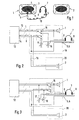
- Figure 1 leaves two speakers 1, 2 of a pair of speakers recognize that in a car radio for playing two various stereo channels are installed in the motor vehicle and are near the rear seats. Speakers 1, 2 each have a loudspeaker aperture 3 and a loudspeaker membrane covering grid 4.
- One speaker 1 of the pair of speakers 1, 2 is with provided a connection socket 5 into which a headphone plug 6 a headphone 7 with two ear speakers 8, 9 insertable is, the headphone plug 6 with the headphones 7 via a flexible connecting cable 10 is connected.
- the loudspeaker 1 is also equipped with a setting regulator 11 for provided the volume of the playback via the headphones 7.
- the arrangement shown in Figure 1 is intended Play 7 stereo programs via the headphones. Because everyone the speaker 1, 2 only for playback one of the two stereo channels is set up, there must be a connection between the speakers 1, 2 are provided, through which the Audio signal for speaker 2 also on headphones 7 arrives.
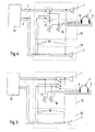
- FIG. 2 A possible wiring of the arrangement according to FIG. 1 is shown in FIG Figure 2 shown.
- a car radio 12 has two outputs 13, 14 for the two stereo channels L and R. Both stereo channels L, R are supplied in the usual way with two-wire lines.
- the two run Stereo channel L wires to the two corresponding connectors of the speaker 1 and the two wires of the Stereo channel R to the two connections of the loudspeaker 2. This normal connection to speakers 1, 2 is established, if a switch 15 is in the switching position, not shown in Figure 2.
- the circuit variant shown in Figure 3 differs only by contacting the potentiometers 16, 17, which - as in Figure 2 - between headphones 7 and Switch 15, but now between switch 15 and car radio 12 are positioned so that the switch 15 only as an off switch works for speakers 1, 2. As a consequence, that the leads to the connector 5 are not be interrupted by the switch 15.
- the potentiometers influence 16, 17 also the volume of playback through the speakers 1, 2.
- a line for the stereo channel R is interrupted and with two wires of a connecting line 19 'to two contacts led to the switching of the speaker 2 in Switches 15 are provided.
- the speaker is accordingly 2 activated or deactivated by the switch 15. In the position of the switch 15 shown in FIG. 4 the loudspeaker 2 is deactivated, so that one wire the connecting line 19 'becomes ineffective while the other Wire is connected to the potentiometer 17.
- the center tap of the potentiometer 17 is with the return line from the ear speaker 9 connected its other end via a third wire the connecting line 19 'with the other wire of the to the housing 20 connected for the loudspeaker 2 stereo channel R. is.
- the potentiometers 16, 17 are connected as in FIG. 2, are only used for volume control for playback via the headphones 7.
- Figure 5 shows an embodiment of the circuit and Wiring according to Figure 4, ie with a three-core connecting line 19 'between the housings 18 and 20, but in the the potentiometers 16, 17 are connected as in FIG. 3, so that with the potentiometers 16, 17 also the volume of the Speaker 1, 2 is adjustable.
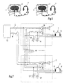
- Figure 6 shows an embodiment of the invention in which both speakers 1, 2 with connection sockets 5 for headphone plugs 6 and each equipped with a setting regulator 11 are.
- both loudspeakers 7, 7 ' on the speakers 1, 2 stereo receptions are possible.
- FIG. 7 shows an embodiment for a corresponding Wiring.
- the stereo channels are in this wiring variant L, R separate from the associated housing 18, 20 of the speakers 1, 2 out.
- Both housings 18, 20 are located Switches 15, 15 ', each with three contacts for the loudspeaker 1 and three contacts for the speaker 2.
- the switches 15, 15 ' are in relation to the two stereo channels L, R connected in series, so that the actuation of a the switch 15, 15 'muting both speakers 1, 2 causes.
- Those with a non-switched wire of the stereo channel L, R connected ear speakers 8, 9 and 8 ', 9' are with their Return lines via the associated potentiometer 16, 17 or 16 ', 17' directly to the relevant return of the stereo channel L or R performed.
- the switches 15, 15 ' are in the Circuit variant according to Figure 7 as in the exemplary embodiments 3 and 5 as a switch for the speakers 1, 2 connected.
- FIG. 7 shows that the between the housings 18, 20 existing connecting line 19 '' five-wire in this case is executed.
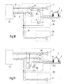
- FIG. 8 A minimal embodiment of the invention is indicated in FIG. 8.
- the loudspeakers 1, 2 have both connection sockets 5 here on, but only the associated channel of the speaker 1, 2 is removable, so that both ear speakers 8, 9 with flexible cables 10 to the associated loudspeaker 1, 2 are routed to the signal for the concerned Tap stereo channel L, R.
- the speaker covers 3 are not provided with adjustment controls 11 in this case.
- FIG. 9 shows a wiring of the arrangement according to FIG. 8. From the car radio 12, the two stereo channels L, R are more common Way to the housing 18, 20 of the speakers 1, 2 out. There is a switch 15, 15 'in each housing, which, however, only has three contacts in this exemplary embodiment for the associated stereo channel 1, 2 L, R is equipped. Is in solid lines the circuitry of the switches 15, 15 'shown as a switch. Alternatively, as shown in dashed lines is, the switch 15, 15 'also as a switch for the speaker 1, 2 can be switched.
- the two speakers 1, 2 via channels L, R with mono signals are supplied so that then on both speakers 1, 2 of Connection of mono headphones or earphones possible and useful is.
- it can be useful for this variant be on the front panels 3 of the speakers 1, 2 separate Provide switch for speakers 1, 2 so that when Connection of only one headphone 7 to the speaker 1 the other Loudspeaker 2 without a headphone 7 can be switched off.
- wireless headphone systems are used when for the the speakers 1, 2 connected receiver the required Power supply is provided. This can be done by a battery powered receiver or by relocating one Power supply for the headphone connection of the loudspeaker 1, 2 be guaranteed.
Landscapes
- Physics & Mathematics (AREA)
- Engineering & Computer Science (AREA)
- Acoustics & Sound (AREA)
- Signal Processing (AREA)
- Otolaryngology (AREA)
- General Health & Medical Sciences (AREA)
- Health & Medical Sciences (AREA)
- Fittings On The Vehicle Exterior For Carrying Loads, And Devices For Holding Or Mounting Articles (AREA)
- Circuit For Audible Band Transducer (AREA)
- Stereophonic System (AREA)
- Input Circuits Of Receivers And Coupling Of Receivers And Audio Equipment (AREA)
- Headphones And Earphones (AREA)
- Stereophonic Arrangements (AREA)
Abstract
Description
- Figur 1
- eine schematische Darstellung eines Lautsprecherpaares, das einen mit einer Anschlußbuchse für einen Kopfhörer ausgestatteten Lautsprecher aufweist,
- Figur 2
- eine erste Ausführungsvariante für eine Beschaltung der Lautsprecher gemäß Figur 1,
- Figur 3
- eine zweite Ausführungsvariante für die Beschaltung der Lautsprecher gemäß Figur 1,
- Figur 4
- eine Schaltungsvariante analog einer Leitungsführung vom Autoradio zu beiden Lautsprechern,
- Figur 5
- eine weitere Schaltungsvariante für die Anordnung gemäß Figur 1 analog Figur 3 mit einer Leitungsführung vom Autoradio zu beiden Lautsprechern,
- Figur 6
- eine schematische Darstellung eines Lautsprecherpaares mit zwei Lautsprechern eines Lautsprecherpaares, an die beide ein Kopfhörer anschließbar ist,
- Figur 7
- eine Ausführungsvariante für eine Beschaltung der Lautsprecheranordnung gemäß Figur 6,
- Figur 8
- eine schematische Darstellung eines Lautsprecherpaares mit Anschlußbuchsen zum Anschluß von Kopfhörersteckern für nur jeweils den betreffenden Kanal des Lautsprechers,
- Figur 9
- ein Ausführungsbeispiel für eine Beschaltung der Anordnung gemäß Figur 8,
- Figur 10
- eine Modifikation der ersten Ausführungsvariante der Beschaltung der Lautsprecher gemäß Figur 2,
- Figur 11
- eine Modifikation der zweiten Aus führungsvariante für die Beschaltung der Lautsprecher gemäß Figur 3.
Claims (9)
- Autoradioanlage mit einem Autoradio (12) und wenigstens zwei an das Autoradio (12) angeschlossenen Lautsprechern (1, 2), dadurch gekennzeichnet, daß wenigstens einer der Lautsprecher (1, 2) mit einer Anschlußbuchse (5) zum Anschluß eines Kopfhörersteckers (6) und mit einem Schalter (15, 15') versehen ist, mit dem die Wiedergabe über die Lautsprecher (1, 2) abschaltbar ist.
- Autoradioanlage nach Anspruch 1, dadurch gekennzeichnet, daß die Anschlußbuchse (5) als den Schalter (15, 15') integrierende Schaltbuchse ausgebildet ist.
- Autoradioanlage nach Anspruch 1 oder 2, dadurch gekennzeichnet, daß eine Verbindung (19, 19', 19'') zwischen zwei zum Empfang von unterschiedlichen Stereokanälen (L, R) vorgesehenen, ein Lautsprecherpaar bildenden Lautsprechern (1, 2) zur Wiedergabe beider Stereokanäle über den Kopfhörer (7) vorgesehen ist.
- Autoradioanlage nach einem der Ansprüche 1 bis 3, dadurch gekennzeichnet, daß eine Verbindung zwischen zwei zum Empfang von unterschiedlichen Stereokanälen (L, R) vorgesehenen, ein Lautsprecherpaar bildenden Lautsprechern (1, 2) vorgesehen ist und daß der Schalter (15, 15') in die Signalleitungen für beide Lautsprecher (1, 2) eingeschaltet ist.
- Autoradioanlage nach einem der Ansprüche 1 bis 4, dadurch gekennzeichnet, daß an dem mit einer Anschlußbuchse (5) versehenen Lautsprecher (1, 2) ein Lautstärkeregler (11) angebracht ist, mit dem die Lautstärke der Wiedergabe über den Kopfhörer (7) regelbar ist.
- Autoradioanlage nach Anspruch 5, dadurch gekennzeichnet, daß der Lautstärkeregler (11) zugleich als Lautstärkeregler des Lautsprechers (1, 2) ausgebildet ist.
- Autoradioanlage nach Anspruch 5 oder 6, dadurch gekennzeichnet, daß der Lautstärkeregler (11) zwei Einstellorgane (16, 17, 16', 17') für beide Lautsprecher (1, 2) eines Lautsprecherpaares aufweist.
- Autoradioanlage nach einem der Ansprüche 3 bis 7, dadurch gekennzeichnet, daß beide Lautsprecher (1, 2) eines Lautsprecherpaares mit einer Anschlußbuchse (5) für jeweils einen Kopfhörer (7) für beide Kanäle (L, R) der Lautsprecher (1, 2) versehen sind.
- Autoradioanlage nach einem der Ansprüche 3 bis 7, dadurch gekennzeichnet, daß beide Lautsprecher (1, 2) eines Lautsprecherpaares mit einer Anschlußbuchse (5) für einen Kopfhöreranschluß (6) für den betreffenden Kanal des Lautsprechers (1, 2) versehen sind.
Applications Claiming Priority (3)
| Application Number | Priority Date | Filing Date | Title |
|---|---|---|---|
| DE19742087 | 1997-09-24 | ||
| DE19742087A DE19742087A1 (de) | 1997-09-24 | 1997-09-24 | Autoradioanlage |
| PCT/DE1998/000901 WO1999016286A1 (de) | 1997-09-24 | 1998-03-28 | Autoradioanlage |
Publications (2)
| Publication Number | Publication Date |
|---|---|
| EP1018288A1 EP1018288A1 (de) | 2000-07-12 |
| EP1018288B1 true EP1018288B1 (de) | 2002-07-03 |
Family
ID=7843438
Family Applications (1)
| Application Number | Title | Priority Date | Filing Date |
|---|---|---|---|
| EP98928089A Expired - Lifetime EP1018288B1 (de) | 1997-09-24 | 1998-03-28 | Autoradioanlage |
Country Status (6)
| Country | Link |
|---|---|
| US (1) | US6567655B1 (de) |
| EP (1) | EP1018288B1 (de) |
| JP (1) | JP2001517917A (de) |
| DE (2) | DE19742087A1 (de) |
| ES (1) | ES2180178T3 (de) |
| WO (1) | WO1999016286A1 (de) |
Families Citing this family (15)
| Publication number | Priority date | Publication date | Assignee | Title |
|---|---|---|---|---|
| US20010044329A1 (en) * | 2000-05-17 | 2001-11-22 | Gil Newsom | Handsfree cellular phone in neckroll enclosure |
| WO2002012022A1 (en) * | 2000-08-07 | 2002-02-14 | Mitsubishi Denki Kabushiki Kaisha | Automotive audiovisual system |
| US20030063756A1 (en) * | 2001-09-28 | 2003-04-03 | Johnson Controls Technology Company | Vehicle communication system |
| JP3989712B2 (ja) * | 2001-11-20 | 2007-10-10 | アルパイン株式会社 | 車載用音響システム |
| JP2004118939A (ja) * | 2002-09-26 | 2004-04-15 | Clarion Co Ltd | 音響装置 |
| JP3880523B2 (ja) * | 2002-09-27 | 2007-02-14 | クラリオン株式会社 | 車載用再生装置 |
| ATE336875T1 (de) * | 2003-02-20 | 2006-09-15 | Sony Ericsson Mobile Comm Ab | Elektronischer treiber zum leiten eines audiosignals zu wahlweise einem von zwei lautsprechern |
| FR2859316A1 (fr) * | 2003-08-29 | 2005-03-04 | Sigismond Sliwinski | Dispositif pour l'ecoute des sons emis par les appareils equipes de haut-parleurs ou enceintes et d'une prise casque |
| US7599498B2 (en) * | 2004-07-09 | 2009-10-06 | Emersys Co., Ltd | Apparatus and method for producing 3D sound |
| DE102007016284A1 (de) * | 2007-04-04 | 2008-10-16 | Giga-Byte Technology Co., Ltd., Hsin-Tien | Tonausgabevorrichtung mit Ohrhörerbetriebsart und Lautsprecherbetriebsart |
| JP5040528B2 (ja) * | 2007-08-28 | 2012-10-03 | ソニー株式会社 | オーディオ信号送信装置、オーディオ信号受信装置及びオーディオ信号伝送方法 |
| JP5192901B2 (ja) * | 2007-10-29 | 2013-05-08 | 株式会社オーディオテクニカ | ノイズキャンセルヘッドホン |
| CN102457798A (zh) * | 2010-10-18 | 2012-05-16 | 鸿富锦精密工业(深圳)有限公司 | 音频切换电路及具有该音频切换电路的音频播放装置 |
| DE102011106030B9 (de) * | 2011-06-30 | 2016-08-11 | Austriamicrosystems Ag | Detektionsschaltung und Detektionsverfahren |
| EP2894874A1 (de) * | 2014-01-14 | 2015-07-15 | Pentac Limited | Kopfhörer |
Family Cites Families (8)
| Publication number | Priority date | Publication date | Assignee | Title |
|---|---|---|---|---|
| US3829624A (en) * | 1973-04-02 | 1974-08-13 | Educational Electronics Inc | Headset and method of making it |
| US4324951A (en) * | 1980-04-28 | 1982-04-13 | Brown Bruce J | Acoustic coupling system |
| DE3126117A1 (de) * | 1981-07-02 | 1983-01-20 | Blaupunkt-Werke Gmbh, 3200 Hildesheim | Autoradio - kassettengeraet |
| JPS61102827A (ja) * | 1984-10-25 | 1986-05-21 | Matsushita Electric Ind Co Ltd | ラジオ受信機の出力切換回路 |
| US4706273A (en) * | 1985-11-14 | 1987-11-10 | Anthony P. Palett | Cellular telephone |
| JPS6472607A (en) * | 1987-09-12 | 1989-03-17 | Sony Corp | Headphone switching circuit |
| US5661811A (en) | 1994-08-25 | 1997-08-26 | Delco Electronics Corporation | Rear seat audio control with multiple media |
| US6330337B1 (en) * | 2000-01-19 | 2001-12-11 | Visteon Global Technologies, Inc. | Automotive entertainment system for rear seat passengers |
-
1997
- 1997-09-24 DE DE19742087A patent/DE19742087A1/de not_active Withdrawn
-
1998
- 1998-03-28 WO PCT/DE1998/000901 patent/WO1999016286A1/de not_active Ceased
- 1998-03-28 ES ES98928089T patent/ES2180178T3/es not_active Expired - Lifetime
- 1998-03-28 DE DE59804689T patent/DE59804689D1/de not_active Expired - Fee Related
- 1998-03-28 EP EP98928089A patent/EP1018288B1/de not_active Expired - Lifetime
- 1998-03-28 US US09/509,220 patent/US6567655B1/en not_active Expired - Fee Related
- 1998-03-28 JP JP2000513443A patent/JP2001517917A/ja active Pending
Also Published As
| Publication number | Publication date |
|---|---|
| DE59804689D1 (de) | 2002-08-08 |
| EP1018288A1 (de) | 2000-07-12 |
| US6567655B1 (en) | 2003-05-20 |
| WO1999016286A1 (de) | 1999-04-01 |
| ES2180178T3 (es) | 2003-02-01 |
| DE19742087A1 (de) | 1999-03-25 |
| JP2001517917A (ja) | 2001-10-09 |
Similar Documents
| Publication | Publication Date | Title |
|---|---|---|
| EP1018288B1 (de) | Autoradioanlage | |
| DE19981794B3 (de) | Akustische Vorrichtung und Kopfhörer | |
| DE3126117C2 (de) | ||
| DE19839250B4 (de) | Audiosignalausgabeapparat für simultane Ausgabe von unterschiedlichen Audiosignalen, die in einem Multiplex-Audiosignal enthalten sind, über Lautsprecher und Kopfhörer | |
| US4210784A (en) | Speaker system | |
| DE102009056798A1 (de) | Audio-Kopfstütze zum Anbringen an einem Fahrzeugsitz | |
| DE19725898B4 (de) | Entertainmentsystem für ein Kraftfahrzeug | |
| DE4030121A1 (de) | Mehrkanal-audiowiedergabevorrichtung und -verfahren | |
| DE102021102794A1 (de) | Ohrhörer-Gerät, Kopfhörer-Gerät und Tonwiedergabegerät | |
| EP0806851B1 (de) | Rundfunkempfangssystem für ein Fahrzeug, mit mehreren Empfangseinheiten, mit Erfassung der im Funkprogramm enthaltenen Zusatzdaten | |
| DE2532238C3 (de) | Akustisches Kombinationsgerät | |
| DE3034522C2 (de) | Lautsprechereinheit für Kraftfahrzeuge | |
| DE60125983T2 (de) | Im fahrzeug angebrachter stereo-schallfeldwandler | |
| DE2840713B2 (de) | Anlage zur Übertragung von Sprache und Musik zn einer Mehrzahl von Sitzen, insbesondere Sitzen eines Fahrzeuges | |
| DE4408930A1 (de) | Kombinationsgerät | |
| EP0659029B1 (de) | Einrichtung zum Umschalten eines Lautsprechers | |
| DE4326328A1 (de) | Audioeinrichtung in einem Kraftfahrzeug | |
| DE2806580A1 (de) | Fernsehempfangsgeraet mit integriertem stereo-rundfunk-empfangsteil mit variabler lautsprecher-beschaltung, bzw. lautsprecher-aufstellung | |
| DE4141843B4 (de) | Verfahren zur Steuerung der Signalwiedergabe von gemischten Musik- und Sprachsignalen, Schaltungsanordnungen zum Durchführen des Verfahrens sowie Anwendungen des Verfahrens bzw. der Schaltungsanordnung | |
| DE3124015C2 (de) | Stereoanlage für Personenkraftwagen | |
| DE2917078C2 (de) | ||
| DE4237710A1 (en) | Improving head related sound characteristics for TV audio signal playback - using controlled audio signal processing for conversion into stereo audio signals | |
| DE19741595C2 (de) | Verfahren zur drahtlosen Übertragung von Audiosignalen, Audiogerät und Tonwiedergabevorrichtung | |
| DE10057261C2 (de) | Audiosystem für ein Kraftfahrzeug | |
| DE19735545C1 (de) | Vorrichtung zur Wiedergabe von Audiosignalen in einem Kraftfahrzeug |
Legal Events
| Date | Code | Title | Description |
|---|---|---|---|
| PUAI | Public reference made under article 153(3) epc to a published international application that has entered the european phase |
Free format text: ORIGINAL CODE: 0009012 |
|
| 17P | Request for examination filed |
Effective date: 20000425 |
|
| AK | Designated contracting states |
Kind code of ref document: A1 Designated state(s): DE ES GB IT |
|
| GRAG | Despatch of communication of intention to grant |
Free format text: ORIGINAL CODE: EPIDOS AGRA |
|
| 17Q | First examination report despatched |
Effective date: 20010718 |
|
| GRAG | Despatch of communication of intention to grant |
Free format text: ORIGINAL CODE: EPIDOS AGRA |
|
| GRAH | Despatch of communication of intention to grant a patent |
Free format text: ORIGINAL CODE: EPIDOS IGRA |
|
| GRAH | Despatch of communication of intention to grant a patent |
Free format text: ORIGINAL CODE: EPIDOS IGRA |
|
| GRAA | (expected) grant |
Free format text: ORIGINAL CODE: 0009210 |
|
| AK | Designated contracting states |
Kind code of ref document: B1 Designated state(s): DE ES GB IT |
|
| REF | Corresponds to: |
Ref document number: 59804689 Country of ref document: DE Date of ref document: 20020808 |
|
| GBT | Gb: translation of ep patent filed (gb section 77(6)(a)/1977) |
Effective date: 20020926 |
|
| REG | Reference to a national code |
Ref country code: ES Ref legal event code: FG2A Ref document number: 2180178 Country of ref document: ES Kind code of ref document: T3 |
|
| PGFP | Annual fee paid to national office [announced via postgrant information from national office to epo] |
Ref country code: ES Payment date: 20030311 Year of fee payment: 6 |
|
| PLBE | No opposition filed within time limit |
Free format text: ORIGINAL CODE: 0009261 |
|
| STAA | Information on the status of an ep patent application or granted ep patent |
Free format text: STATUS: NO OPPOSITION FILED WITHIN TIME LIMIT |
|
| 26N | No opposition filed |
Effective date: 20030404 |
|
| PGFP | Annual fee paid to national office [announced via postgrant information from national office to epo] |
Ref country code: GB Payment date: 20040305 Year of fee payment: 7 |
|
| PG25 | Lapsed in a contracting state [announced via postgrant information from national office to epo] |
Ref country code: ES Free format text: LAPSE BECAUSE OF NON-PAYMENT OF DUE FEES Effective date: 20040329 |
|
| PG25 | Lapsed in a contracting state [announced via postgrant information from national office to epo] |
Ref country code: IT Free format text: LAPSE BECAUSE OF NON-PAYMENT OF DUE FEES;WARNING: LAPSES OF ITALIAN PATENTS WITH EFFECTIVE DATE BEFORE 2007 MAY HAVE OCCURRED AT ANY TIME BEFORE 2007. THE CORRECT EFFECTIVE DATE MAY BE DIFFERENT FROM THE ONE RECORDED. Effective date: 20050328 Ref country code: GB Free format text: LAPSE BECAUSE OF NON-PAYMENT OF DUE FEES Effective date: 20050328 |
|
| REG | Reference to a national code |
Ref country code: ES Ref legal event code: FD2A Effective date: 20040329 |
|
| GBPC | Gb: european patent ceased through non-payment of renewal fee |
Effective date: 20050328 |
|
| PGFP | Annual fee paid to national office [announced via postgrant information from national office to epo] |
Ref country code: DE Payment date: 20090624 Year of fee payment: 12 |
|
| PG25 | Lapsed in a contracting state [announced via postgrant information from national office to epo] |
Ref country code: DE Free format text: LAPSE BECAUSE OF NON-PAYMENT OF DUE FEES Effective date: 20101001 |