EP1016610B1 - Vorrichtung zum Transport von einander zu überlappenden Bögen, insbesondere Papierbögen - Google Patents
Vorrichtung zum Transport von einander zu überlappenden Bögen, insbesondere Papierbögen Download PDFInfo
- Publication number
- EP1016610B1 EP1016610B1 EP99121102A EP99121102A EP1016610B1 EP 1016610 B1 EP1016610 B1 EP 1016610B1 EP 99121102 A EP99121102 A EP 99121102A EP 99121102 A EP99121102 A EP 99121102A EP 1016610 B1 EP1016610 B1 EP 1016610B1
- Authority
- EP
- European Patent Office
- Prior art keywords
- sheets
- edge portion
- transfer region
- sheet
- conveyor
- Prior art date
- Legal status (The legal status is an assumption and is not a legal conclusion. Google has not performed a legal analysis and makes no representation as to the accuracy of the status listed.)
- Expired - Lifetime
Links
- 230000015572 biosynthetic process Effects 0.000 title 1
- 238000012546 transfer Methods 0.000 claims description 40
- 230000006870 function Effects 0.000 claims description 11
- 238000000034 method Methods 0.000 claims description 7
- 239000000123 paper Substances 0.000 description 24
- 239000003570 air Substances 0.000 description 20
- 238000012545 processing Methods 0.000 description 5
- 239000012080 ambient air Substances 0.000 description 2
- 230000007613 environmental effect Effects 0.000 description 2
- 230000001105 regulatory effect Effects 0.000 description 2
- 230000001276 controlling effect Effects 0.000 description 1
- 238000013461 design Methods 0.000 description 1
- 238000011161 development Methods 0.000 description 1
- 239000000463 material Substances 0.000 description 1
- 238000013021 overheating Methods 0.000 description 1
- 238000011144 upstream manufacturing Methods 0.000 description 1
Images

Classifications
-
- B—PERFORMING OPERATIONS; TRANSPORTING
- B65—CONVEYING; PACKING; STORING; HANDLING THIN OR FILAMENTARY MATERIAL
- B65H—HANDLING THIN OR FILAMENTARY MATERIAL, e.g. SHEETS, WEBS, CABLES
- B65H29/00—Delivering or advancing articles from machines; Advancing articles to or into piles
- B65H29/68—Reducing the speed of articles as they advance
- B65H29/686—Pneumatic brakes
-
- B—PERFORMING OPERATIONS; TRANSPORTING
- B65—CONVEYING; PACKING; STORING; HANDLING THIN OR FILAMENTARY MATERIAL
- B65H—HANDLING THIN OR FILAMENTARY MATERIAL, e.g. SHEETS, WEBS, CABLES
- B65H29/00—Delivering or advancing articles from machines; Advancing articles to or into piles
- B65H29/66—Advancing articles in overlapping streams
- B65H29/6609—Advancing articles in overlapping streams forming an overlapping stream
- B65H29/6618—Advancing articles in overlapping streams forming an overlapping stream upon transfer from a first conveyor to a second conveyor advancing at slower speed
- B65H29/6627—Advancing articles in overlapping streams forming an overlapping stream upon transfer from a first conveyor to a second conveyor advancing at slower speed in combination with auxiliary means for overlapping articles
-
- B—PERFORMING OPERATIONS; TRANSPORTING
- B65—CONVEYING; PACKING; STORING; HANDLING THIN OR FILAMENTARY MATERIAL
- B65H—HANDLING THIN OR FILAMENTARY MATERIAL, e.g. SHEETS, WEBS, CABLES
- B65H2406/00—Means using fluid
- B65H2406/30—Suction means
- B65H2406/31—Suction box; Suction chambers
-
- B—PERFORMING OPERATIONS; TRANSPORTING
- B65—CONVEYING; PACKING; STORING; HANDLING THIN OR FILAMENTARY MATERIAL
- B65H—HANDLING THIN OR FILAMENTARY MATERIAL, e.g. SHEETS, WEBS, CABLES
- B65H2801/00—Application field
- B65H2801/03—Image reproduction devices
- B65H2801/21—Industrial-size printers, e.g. rotary printing press
Definitions
- the invention relates to a device for transporting overlapping one another Sheets, in particular sheets of paper, with a first transport device for individually feeding the sheets to a transfer area, one second transport device for receiving the from the first transport device individually fed sheets in the transfer area and to the subsequent one
- These sheets are transported in an overlapping arrangement from the transfer area out and with a deflection device that the trailing Edge section of each sheet in the transfer area from the feed plane of the leading edge section of the following sheet deflects the individual arches with an angled, preferably transverse to acted upon this directed admission force and with a control device to control an acting force.
- the invention also relates to a method for transporting overlapping one another Sheets, especially sheets of paper, in which the sheets pass through a first transport device is fed individually to a transfer area, picked up by a second transport device in the transfer area and transported in an overlapping arrangement from the transfer area with the trailing edge section of each sheet in the transfer area from the feed plane of the leading edge section of each trailing sheet deflected out by a deflector is by the individual arches with an angled, preferably transverse, to these directional loading force applied by a control device is controlled.
- Such a transport device and such a method are usually found Use in a paper processing machine, in the paper webs through cross cutting or combined longitudinal and cross cutting individual sheets can be cut. Then the individual Sheets are stacked in groups on top of one another and the stacks thus formed are processed further, for example packaged or bound into blocks. To do this the individual sheets in the transfer area are overlapping in mutual Arrangement are brought together, for which the arches from a braking device be slowed down. Because the following arc in the area the braking device continues to run unchecked, its front edge pushes over the rear edge of the already braked leading sheet, whereby the sheets overlap and then in a so-called Scale flow can be transported further.
- the admission device ensures that the trailing edge of the leading sheet comes out of the feed plane the leading edge of the following sheet is deflected out becomes.
- the trailing edge of the leading sheet lowered compared to the leading edge of the subsequent sheet, see above that the latter can gently run onto the leading sheet.
- a device and a method of the type mentioned are known from the DE 26 01 081 A1 known.
- Devices of the described in this document Art are widely used in paper processing machines, in which paper webs are processed into individual sheets or blocks.
- this known device have the first and second transport devices each driven endless belts on which the sheets to get promoted.
- Upper bands are on the top of the sheets for guiding the sheets on.
- the transport speed of the endless belts of the first Transport device which corresponds to the speed of the upper belts, is higher than that of the endless belts of the second transport device.
- an overlap of the individual Sheets achieved because the sheets are fed through the first transport device in the transfer area takes place faster than the removal through the second transport device.
- the application device is as Suction or vacuum device formed on the underside of the trailing Edge section of the sheet when this is from the second transport device an air flow is moved out of the transfer area generated against the direction of sheet travel.
- This creates a negative pressure that the trailing edge section of this sheet compared to the leading Edge section of the following sheet pulls down and thus out of Feed plane of the leading edge section of the following sheet distracts out.
- the air flow in this known device deflected upward in the upstream end of the transfer area, whereby the leading edge section of the following sheet little is raised.
- the following sheet runs smoothly on the leading one Arch overlaps and overlaps to form the shingled stream.
- US 4,221,377 discloses a device for slowing down and stacking Sheets of paper revealed in containers without the leading edge by stop to damage on an opposite container wall.
- there sheets of paper are leading through a suction device slowed down.
- the sheets of paper are removed from the feed direction of the following bow is deflected out of her Be tilted. A leading edge of the trailing The sheet can then pass over the trailing edge of the leading sheet slide.
- the suction force of the suction device is controllable.
- the slowed down Sheets are fed directly to a container. Because of their low Speed becomes leading edge of the sheet by hitting it the opposite container wall is no longer damaged.
- US 4,776,577 relates to an overlap device Sensitive, especially moist, corrugated cardboard sheets transported one after the other.
- An intake device is controlled in such a way that the preceding one Section of the arches less and the trailing section of the Arches, on the other hand, are sucked more strongly in order to form a transverse wave of the damp To prevent corrugated cardboard.
- the device at the beginning mentioned type the control device depending on the application force on the transport speed of the first and / or second transport device controls such that the loading force at a relatively low transport speed relatively small and at a relatively high transport speed is relatively high.
- the object is also achieved in that the method at the beginning mentioned type the application force depending on the control device on the transport speed of the first and / or second transport device is controlled so that the loading force at relative low transport speed relatively small and at a relatively high transport speed is relatively high.
- control device controls the application force depending on additional operating parameters the device such as transport speed and / or Number of sheets to be overlapped, properties of the sheets such as Thickness, specific weight (grammage) and / or length of the edge sections the arches and / or environmental conditions such as Humidity and / or temperature.
- the Beauischagungs can optimally to the respective operating state can be set, which is always an optimal and reliable and thus economical operation of the device can be guaranteed. It has it turned out that for an optimal and reliable and thus economical operation the correct setting of the application force is essential.
- a currently particularly preferred embodiment of the invention is characterized is characterized in that the control device has a memory in which Characteristic curves and / or functions are stored depending on the Operating parameters of the device, properties of the sheets to be treated and or ambient conditions have certain values for the force of action specify.
- the course of the characteristic curves or the functions can be freely selected become. For example, several discontinuities can be provided. Furthermore, the course of the characteristic curves can have jumps.
- the characteristics or functions can also be linear, but this is not absolutely necessary have to be.
- control device can reduce the application force to a lower one Limit and / or limit an upper limit. These limits are freely selectable depending on the application.
- the loading force can be linearly proportional to the transport speed run. However, this is not mandatory. There are other functions too, in particular depending on the respective application, conceivable.
- the Functions can be continuous or have discontinuities. In the latter In this case, it is also conceivable, for example, to apply the force below a predetermined minimum speed on a preselected lower one Limit value, which can also be zero, for example, and / or above one predetermined speed value on a preselected upper one To keep the limit constant.
- the limit of the acting force on a lower limit, preferably zero, below a predetermined one Minimum speed and an upper limit above a predetermined Speed value takes into account the fact that at low Transport speeds a collision between the trailing edge of the leading sheet and the leading edge of the following sheet in general is not to be feared and at high transport speeds further increase in the acting force is no longer required to make a ensure safe and bumpless opening of the sheets on top of each other.
- the application force below a predetermined minimum speed to zero could be reached when the Minimum speed the acting force jumps to a minimum value be raised, which takes into account the fact that not least due to the influence of friction and Stiffness of the sheet material a noticeable distraction of the trailing Edge section of the sheets from the feed plane only at a certain Minimum loading force can be achieved.
- the transport speed of the first transport device is usually higher than that of the second transport device, not least because the sheets in the Transfer area to achieve a mutual overlap of one Braking device are braked accordingly. In this case, at least when the transport speed of the first transport device is at a standstill the control of the loading force depending on the transport speed the first transport device.
- the Transport speed of the first transport device in a paper processing Machine in a fixed ratio to the pulling speed of the Paper web from the paper roll, also called machine speed is alternatively also the acting force depending on the pulling speed can be controlled.
- the deflection device expediently has suction means for generation a suction force acting on the arches, which is consequently is the application force to be set by the control device.
- the suction means work on the "Airfoil" principle by the Suction means a blower or an ejector for generating an air flow and means for directing the air flow along one side of the trailing one Edge portion of the sheets have a pressure drop and thus a Generate negative pressure of the trailing edge section of the leading Sheet from the feed plane of the leading edge section of the deflects each subsequent bow out.
- control device controls the volume flow rate the air or the pressure of the air flow.
- the control device controls the performance of the blower.
- a frequency-controlled Blowers can be provided by which the volume flow of the air is regulated is, by using a predetermined setpoint, the speed of the fan and thus the volume flow is changed. Because frequency controlled However, do not let the blower run down to zero a flap may be provided to completely shut off the air supply can. Nevertheless, the advantage of this design is that the blower according to a predetermined setpoint from the control device their speed changes and so the desired airflow is available provides.
- air can pass between the outlet of the Blower and the means for directing the air flow a movable slide be arranged, which is opened and closed with the aid of a drive, which is controlled accordingly by the control device.
- a movable slide be arranged, which is opened and closed with the aid of a drive, which is controlled accordingly by the control device.
- the drive of the Slider can be implemented, for example, electrically or pneumatically.
- a pressure relief valve should be provided.
- the compressed air entrains the ambient air, which increases the volume flow multiplied in the air.
- the advantage of this version is that low noise emission as well as easy controllability by the blown air can be controlled by a simple proportional valve in the compressed air supply line.
- the at least one conveyor belt has, between the inside of the one hand and the first and second Transport devices and the deflecting device on the other hand guided the sheet are an adjusting device for adjusting the distance of the conveyor belt provided by the deflection device in the transfer area.
- this setting device With the help of this setting device, the course of the conveyor belt or the Conveyor belts set or fixed above the deflection device.
- This Execution is particularly suitable for a working on the "Airfoil" principle Deflection device, for a safe function of such a deflection device the distance or gap between the conveyor belt or the Conveyor belts on the one hand and the deflection device on the other hand and the Angle at which the conveyor belt runs or the Conveyor belts run is of great importance.
- this version also has an independent inventive concept forms, in which the control of the application force plays no role and is therefore not necessary in principle, so that here to the previously discussed Control device also waive and the application force fixed can be.
- the setting device can at least have an adjustable roller on which the conveyor belt with its Outside is guided.
- the conveyor belt can also for example by means of a sheet, a rod or individual rolls be performed.
- Conveyor belt is usually an upper belt that the first and second transport devices covered sheets and over the first and second transport devices and the speed of which Transport speed of the first transport device adapted accordingly is.
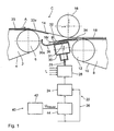
- the device shown in Figure 1 is preferably used in a paper processing machine, in the paper webs to individual sheets or Blocks are processed. To do this, a paper web is taken from a paper roll withdrawn and passed to a cutting device in which the paper web Cross cutting or combined longitudinal and cross cutting to single sheets is cut. Then the individual sheets become the one after the other transported arrangement shown in Figure 1.
- the cutter Around the cut arches to separate behind the cutting device, i.e. to separate them from each other the individual sheets the cutter at a higher speed than the previously mentioned peeling speed at which the paper web of the paper roll is transported to the cutting device and usually is also referred to as machine speed.
- the transport device that the individual sheets from (not in the figures shown) transported to the arrangement shown in Figure 1, is indicated schematically in FIG. 1 with the reference symbol 2 and is hereinafter referred to as the first transport device.
- the first transport facility 2 has a plurality of continuous endless belts 4 lying parallel to one another on, which are guided in the arrangement of Figure 1 around an end roller 6.
- first transport device 2 run in a corresponding arrangement parallel upper belts 14, 6 endless belts on the end roller 4 leave, are passed through the transfer area C and then along the outside or top of the upper runs of the endless belts 10 of the continue to run second transport device 8 at a short distance from this.
- the Upper belts 14 are also designed as an endless belt.
- a dab roller 1 6 is arranged through which the upper belts 14 guided and, as can be seen in Figure 1, in the direction of the second transport device 8 are deflected a little.
- the roller 16 is both approximately in the longitudinal direction the upper belts 14 as well as adjustable perpendicular to them.
- the upper belt 14 can, for example, also with the help of a sheet, a rod or individual rolls.
- the runs of the upper belts 14 shown in FIG. 1 run from FIG left to right according to the direction of sheet travel according to arrow A.
- the endless belts 4 and 10 are driven so that their upper runs that are adjacent run to the upper bands 14, likewise in the direction of sheet travel according to arrow A. and thus run in the same direction as the upper belts 14.
- the endless belts 4 of the first transport device 2 run at a relatively high level Speed, corresponding to the speed of the upper belt 14 is adjusted. Accordingly, the transport speed of the upper runs is the Endless belts 4 equal to the transport speed of the upper belts 14.
- the endless belts 10 of the second transport device 8 run with a relatively low speed so that the transport speed of the second transport device 8 is less than that of the first transport device 2 is, which is also a difference between the speed of the upper Runs of the endless belts 10 of the second transport device 8 and the upper belts 14 results.
- an application device 22 is provided, a booster 24, which is supplied by a compressed air supply 26 and has an ejector 28 connected to the booster 24.
- the Ejector 28 tears the compressed air received by the booster 24 from the outside Ambient air L with, whereby a relatively large volume flow is generated, the a multiple of the volume flow provided by booster 24 is.
- the air flow thus generated is passed through an outlet 29 into a housing 30 performed, which is arranged in the transfer area C.
- the housing 30 has on it an opening 31 facing the transfer area C, which opens into a gap 32 opens, which of two staggered, overlapping Baffles 34, 36 is formed.
- the first guide plate 34 is adjacent to the end roller 12 of the second transport device 8 is arranged and essentially covers the opening 31 of the housing 30.
- the second baffle 36 is on the Transfer area C facing side of the housing 30 attached and extends towards the end roller 6 of the first transport device 2.
- the adjacent Free end 36a of the end roller 6 of the first transport device 2 second guide plate 36 is bent in the direction of the upper belts 14.
- the loading device 22 shown works according to the so-called "Airfoil" principle.
- the air stream emerging from the gap 32 is through the Baffles 34, 36 guided against the sheet running direction A, which after According to the Bernoulli principle, a pressure drop is generated that follows the trailing edge section 18r of the leading sheet 18 in the direction of the housing 30, that is according to Figure 1 down, sucks and thus from the feed plane of the leading Edge section 20v of the subsequent sheet 20 deflects out.
- the airflow is then in Direction towards the upper belts 14, that is to say deflected upwards according to FIG. 1, whereby the leading edge portion 20v further against the upper belts 14 is pressed. This ensures that the subsequent sheet 20 with its leading edge section 20r on the trailing edge section 18r of the leading sheet 18 can gently emerge, whereby the desired overlap occurs.
- the adjustable already mentioned is Dab roller 16 provided. With it the course of the upper belts 14 can be compared the airfoil nozzle formed by the gap 32 can be set or fixed. By appropriate adjustment of the dab roller 16 can essentially the rest triangular cross section of the between the upper bands 14 and the two Baffles 34, 36 overall geometrically formed in the transfer area C. to be influenced. As already mentioned, the correct course of the upper bands is 14 above the Airfoil nozzle of great importance for its safe function.
- the generated by the application device 22 on the trailing Edge portion 18r of the sheet 18 exerted on the application force Embodiment shown as suction force is expressed by a control device 40 controlled.
- the control device 40 controls in the illustrated Embodiment the strength of the suction force or negative pressure.
- control device 40 in the exemplary embodiment shown has a control unit 42 and a downstream proportional valve 44.
- the control unit 42 operates electrically and outputs an electric control signal U control to the proportional valve of which is connected to the compressed air supply 26 and the electric control signal U tax approximately linearly converted into a pneumatic signal, and controls with this signal corresponding to the booster 24th
- the control voltage U tax generated by the control unit 42 depends on the operating parameters of the machine, the properties of the sheets to be processed and / or the ambient conditions; these include the number of paper webs, paper thickness, transport speed, moisture, grammage and section length.
- the control unit 42 contains a memory in which characteristic curves and / or functions are stored which, depending on the aforementioned parameters, indicate values for the control voltage U tax .
- FIGS. 2a and b various characteristic curves are shown in FIGS. 2a and b, in which the control voltage U control is specified as a function of the transport speed v.
- the transport speed v is usually the transport speed of the first transport device 2 or the pulling speed of the paper web from the paper roll (machine speed), since these two speeds are in a fixed relationship to one another. Nevertheless, it is also conceivable to use the transport speed of the second transport device 8, in particular if this is in a fixed relationship to the transport speed of the first transport device 2.
- the characteristic curves shown in Figure 2a have a linear profile, so that the control voltage U control is thus increased and the negative pressure with increase in the transport speed.
- the characteristic curves in the lower speed range are discontinuous in that no control voltage U control and therefore no negative pressure is generated between standstill and a lower speed limit value .
- characteristic curves shown in FIG. 2a are not mandatory. It is also conceivable, characteristic curves with several discontinuities, jumps as well to choose upper and lower limits. Also the course or shape of the Characteristic curves can be freely selected depending on the application; for example a parabolic course is also conceivable. This is exemplified in FIG. 2b directed.
- the volume flow from the gap is accordingly 37 escaping air regulated.
- control device 40 is self-evident also sensors for measuring the operating parameters of the machine, the properties the sheets to be processed and the environmental conditions and / or Has input units for entering these values, which, however, in the figures are not shown in detail and are otherwise known per se.
Landscapes
- Engineering & Computer Science (AREA)
- Mechanical Engineering (AREA)
- Delivering By Means Of Belts And Rollers (AREA)
- Discharge By Other Means (AREA)
- Sheets, Magazines, And Separation Thereof (AREA)
- Making Paper Articles (AREA)
- Separation, Sorting, Adjustment, Or Bending Of Sheets To Be Conveyed (AREA)
Applications Claiming Priority (2)
| Application Number | Priority Date | Filing Date | Title |
|---|---|---|---|
| DE19850901A DE19850901A1 (de) | 1998-11-05 | 1998-11-05 | Vorrichtung zum Transport von einander zu überlappenden Bögen, insbesondere Papierbögen |
| DE19850901 | 1998-11-05 |
Publications (3)
| Publication Number | Publication Date |
|---|---|
| EP1016610A2 EP1016610A2 (de) | 2000-07-05 |
| EP1016610A3 EP1016610A3 (de) | 2001-05-02 |
| EP1016610B1 true EP1016610B1 (de) | 2004-04-14 |
Family
ID=7886718
Family Applications (1)
| Application Number | Title | Priority Date | Filing Date |
|---|---|---|---|
| EP99121102A Expired - Lifetime EP1016610B1 (de) | 1998-11-05 | 1999-10-22 | Vorrichtung zum Transport von einander zu überlappenden Bögen, insbesondere Papierbögen |
Country Status (7)
| Country | Link |
|---|---|
| US (1) | US6338482B1 (https=) |
| EP (1) | EP1016610B1 (https=) |
| JP (1) | JP2000143066A (https=) |
| AT (1) | ATE264261T1 (https=) |
| DE (2) | DE19850901A1 (https=) |
| ES (1) | ES2216409T3 (https=) |
| PT (1) | PT1016610E (https=) |
Families Citing this family (10)
| Publication number | Priority date | Publication date | Assignee | Title |
|---|---|---|---|---|
| US6543989B1 (en) * | 1999-07-06 | 2003-04-08 | Kraft Foods Holdings, Inc. | Lowering arms stacking apparatus |
| US20030131943A1 (en) * | 2002-01-17 | 2003-07-17 | Frederisy Douglas R. | Apparatus and method for assembling absorbent garments |
| US7021450B2 (en) | 2002-04-17 | 2006-04-04 | Kraft Foods Holdings, Inc. | Device and method to correct uneven spacing of successive articles |
| US20040125416A1 (en) * | 2002-12-27 | 2004-07-01 | Gawlik Noah J. | Method of scanning an image with an electronic scanner |
| US6969059B2 (en) * | 2003-07-16 | 2005-11-29 | Marquip, Llc | Dual modulated vacuum shingler |
| JP4878104B2 (ja) * | 2003-07-21 | 2012-02-15 | ハイデルベルガー ドルツクマシーネン アクチエンゲゼルシヤフト | 印刷機を通じて枚葉紙を搬送するための方法および該方法を実施するための装置 |
| JP2006082923A (ja) * | 2004-09-15 | 2006-03-30 | Canon Inc | シート処理装置及びこれを備えた画像形成装置 |
| DE102006002029A1 (de) * | 2006-01-13 | 2007-07-19 | Bielomatik Jagenberg Gmbh + Co. Kg | Vorrichtung zum Abbremsen von auf einem Stapel abzulegenden Bögen, insbesondere Papier-oder Kartonbögen |
| SE0701892L (sv) * | 2007-08-20 | 2009-01-13 | Lasermax Roll Systems Ab | Anordning för stapling av ark |
| ATE486333T1 (de) * | 2007-09-07 | 2010-11-15 | Frama Ag | Verfahren zum frankieren, bedrucken und bebildern von flachen versandobjekten |
Family Cites Families (17)
| Publication number | Priority date | Publication date | Assignee | Title |
|---|---|---|---|---|
| GB970959A (en) * | 1962-09-27 | 1964-09-23 | Masson Scott & Company Ltd | Improvements in and relating to the handling of sheet materials |
| US3315956A (en) * | 1964-06-22 | 1967-04-25 | Smith And Winchester Mfg Compa | High speed sheet feeding and overlapping system |
| US3380734A (en) * | 1966-04-19 | 1968-04-30 | Kimberly Clark Co | Papermaking machine |
| US3975012A (en) * | 1974-11-04 | 1976-08-17 | Maxson Automatic Machinery Company | Overlapped sheet-feeding machine |
| DE2601081A1 (de) * | 1976-01-13 | 1977-07-21 | Maxson Automatic Mach | Verfahren und maschine zum zufuehren von ueberlappten bogen |
| DE2725547C2 (de) * | 1977-06-07 | 1983-12-22 | De La Rue Giori S.A., 1003 Lausanne | Verfahren und Vorrichtung zum fächerartigen Übereinanderschieben von bogen- oder heftförmigen Gegenständen |
| DE2755160C3 (de) * | 1977-12-10 | 1980-11-06 | Jagenberg-Werke Ag, 4000 Duesseldorf | Vorrichtung zum Abbremsen und Überlappen von auf einer Ablage als Stapel abzulegenden Bogen oder Bogenpaketen |
| US4436302A (en) * | 1981-05-28 | 1984-03-13 | Beloit Corporation | Apparatus for slowing down and preventing edge damage on moving sheets |
| DE3413179C2 (de) * | 1984-04-07 | 1995-02-23 | Roland Man Druckmasch | Steuer- und Regelvorrichtung eines Bogenauslegers für bogenverarbeitende Maschinen, insbesondere für Bogendruckmaschinen |
| US4776577A (en) * | 1987-03-10 | 1988-10-11 | Marquip, Inc. | Shingling of delicate conveyed sheet material |
| DE4119511A1 (de) * | 1991-06-13 | 1992-12-17 | Jagenberg Ag | Vorrichtung zum abbremsen von auf einem stapel abzulegenden boegen, insbesondere papier- oder kartonboegen |
| DE4201480C2 (de) * | 1992-01-21 | 1997-02-13 | Heidelberger Druckmasch Ag | Einrichtung zum Ablegen von bedruckten Bogen auf einen Stapel |
| DE4220582A1 (de) * | 1991-08-16 | 1993-02-18 | Heidelberger Druckmasch Ag | Einrichtung zur regelung und/oder steuerung einzelner stellelemente im auslegerbereich einer druckmaschine |
| US5265862A (en) * | 1992-09-25 | 1993-11-30 | Numerical Concepts, Inc. | Sheeter for recycled and lightweight paper stocks |
| DE4307383A1 (de) | 1993-03-09 | 1994-09-15 | Jagenberg Ag | Vorrichtung zum Abbremsen von Bögen, insbesondere von Papierbögen |
| DE19616714A1 (de) * | 1996-04-26 | 1997-11-06 | Heidelberger Druckmasch Ag | Vorrichtung zum Fördern eines insbesondere geschuppten Stroms von Bogen zu einer bogenverarbeitenden Maschine |
| GB9706898D0 (en) * | 1997-04-04 | 1997-05-21 | Strachan & Henshaw Machinery | Transporting sheets |
-
1998
- 1998-11-05 DE DE19850901A patent/DE19850901A1/de not_active Withdrawn
-
1999
- 1999-10-22 AT AT99121102T patent/ATE264261T1/de not_active IP Right Cessation
- 1999-10-22 EP EP99121102A patent/EP1016610B1/de not_active Expired - Lifetime
- 1999-10-22 ES ES99121102T patent/ES2216409T3/es not_active Expired - Lifetime
- 1999-10-22 PT PT99121102T patent/PT1016610E/pt unknown
- 1999-10-22 DE DE59909170T patent/DE59909170D1/de not_active Expired - Fee Related
- 1999-11-05 JP JP11315133A patent/JP2000143066A/ja not_active Withdrawn
- 1999-11-05 US US09/434,301 patent/US6338482B1/en not_active Expired - Fee Related
Also Published As
| Publication number | Publication date |
|---|---|
| ES2216409T3 (es) | 2004-10-16 |
| PT1016610E (pt) | 2004-09-30 |
| DE19850901A1 (de) | 2000-05-11 |
| JP2000143066A (ja) | 2000-05-23 |
| DE59909170D1 (de) | 2004-05-19 |
| US6338482B1 (en) | 2002-01-15 |
| EP1016610A2 (de) | 2000-07-05 |
| EP1016610A3 (de) | 2001-05-02 |
| ATE264261T1 (de) | 2004-04-15 |
Similar Documents
| Publication | Publication Date | Title |
|---|---|---|
| EP0454011B1 (de) | Vorrichtung zum Fördern eines insbesondere geschuppten Stroms von Bogen | |
| DE3525040C2 (de) | Einrichtung zur Umlenkung der Förderrichtung von Papierblättern | |
| EP1595836B1 (de) | Vorrichtung zur Verarbeitung von Stapeln aus elektrostatisch aufladbaren Flachteilen | |
| DE3844899C2 (de) | Verzögerungs-Vorrichtung für Bogenlagen | |
| EP1016610B1 (de) | Vorrichtung zum Transport von einander zu überlappenden Bögen, insbesondere Papierbögen | |
| DE4435988A1 (de) | Vorrichtung zum Abbremsen von Bogen | |
| EP0680908A1 (de) | Vorrichtung zur Anpassung des Unterdruckes in einem Saugbandzuführtisch eines Bogenanlegers | |
| EP0888992B1 (de) | Anlegetisch zum taktmässigen Fördern von Bogen zu einer Bogen verarbeitenden Maschine | |
| DE3537898A1 (de) | Anlage zum auffaechern und stapeln von gefoerdertem blattmaterial mit einer vor-auffaecherungssteuerung der blattmaterial-zufuehrung | |
| DE3805779A1 (de) | Vorrichtung und verfahren zum schindeln von einzelnen, nacheinander von stromauf nach stromab gefoerderten blaettern | |
| EP1214264B1 (de) | Vorrichtung zum querschneiden von materialbahnen, insbesondere kartonbahnen | |
| DE4139888A1 (de) | Vorrichtung zum abbremsen von auf einem stapel abzulegenden boegen, insbesondere papier- oder kartonboegen | |
| EP1524227A2 (de) | Verfahren zur Verwendung eines Falzapparates | |
| EP1593628A2 (de) | Vorrichtung zum Fördern und gleichzeitigen Ausrichten von Bogen | |
| AT400856B (de) | Vorrichtung zum überführen einer faserstoffbahn | |
| EP0798251A2 (de) | Saugförderer | |
| DE69612683T2 (de) | Züfuhrungsvorrichtung für geschnittenen Tabak für eine Zigarettenherstellungsmaschine | |
| DE102006018769B3 (de) | Vorrichtung zum Transport bogenförmiger flacher Gegenstände | |
| DE102012206848B4 (de) | Entnahmevorrichtung zur Entnahme von Flachteilen | |
| EP2128063A2 (de) | Fördereinrichtung für Bogenlagen und Verfahren zum Bilden und Fördern eines Schuppenstroms aus Bogenlagen | |
| DE19649824A1 (de) | Saugförderer | |
| EP2316767B1 (de) | Verfahren und Vorrichtung zum Herstellen von Stapeln aus Druckprodukten | |
| EP3619153B1 (de) | Vorrichtung und verfahren zur bildung eines schuppenstroms von unterlappenden bögen | |
| DE2532880A1 (de) | Vorrichtung zum stapelweisen ablegen von hintereinander gefoerderter bogen | |
| EP1522513A2 (de) | Vorrichtung zum Vereinzeln von aufgeschuppten, flachen Produkten |
Legal Events
| Date | Code | Title | Description |
|---|---|---|---|
| PUAI | Public reference made under article 153(3) epc to a published international application that has entered the european phase |
Free format text: ORIGINAL CODE: 0009012 |
|
| AK | Designated contracting states |
Kind code of ref document: A2 Designated state(s): AT BE CH CY DE DK ES FI FR GB GR IE IT LI LU MC NL PT SE |
|
| AX | Request for extension of the european patent |
Free format text: AL;LT;LV;MK;RO;SI |
|
| PUAL | Search report despatched |
Free format text: ORIGINAL CODE: 0009013 |
|
| AK | Designated contracting states |
Kind code of ref document: A3 Designated state(s): AT BE CH CY DE DK ES FI FR GB GR IE IT LI LU MC NL PT SE |
|
| AX | Request for extension of the european patent |
Free format text: AL;LT;LV;MK;RO;SI |
|
| 17P | Request for examination filed |
Effective date: 20011102 |
|
| AKX | Designation fees paid |
Free format text: AT BE CH CY DE DK ES FI FR GB GR IE IT LI LU MC NL PT SE |
|
| 17Q | First examination report despatched |
Effective date: 20021220 |
|
| GRAP | Despatch of communication of intention to grant a patent |
Free format text: ORIGINAL CODE: EPIDOSNIGR1 |
|
| GRAS | Grant fee paid |
Free format text: ORIGINAL CODE: EPIDOSNIGR3 |
|
| GRAA | (expected) grant |
Free format text: ORIGINAL CODE: 0009210 |
|
| AK | Designated contracting states |
Kind code of ref document: B1 Designated state(s): AT BE CH CY DE DK ES FI FR GB GR IE IT LI LU MC NL PT SE |
|
| PG25 | Lapsed in a contracting state [announced via postgrant information from national office to epo] |
Ref country code: NL Free format text: LAPSE BECAUSE OF FAILURE TO SUBMIT A TRANSLATION OF THE DESCRIPTION OR TO PAY THE FEE WITHIN THE PRESCRIBED TIME-LIMIT Effective date: 20040414 Ref country code: IE Free format text: LAPSE BECAUSE OF FAILURE TO SUBMIT A TRANSLATION OF THE DESCRIPTION OR TO PAY THE FEE WITHIN THE PRESCRIBED TIME-LIMIT Effective date: 20040414 Ref country code: CY Free format text: LAPSE BECAUSE OF FAILURE TO SUBMIT A TRANSLATION OF THE DESCRIPTION OR TO PAY THE FEE WITHIN THE PRESCRIBED TIME-LIMIT Effective date: 20040414 |
|
| REG | Reference to a national code |
Ref country code: GB Ref legal event code: FG4D Free format text: NOT ENGLISH |
|
| REG | Reference to a national code |
Ref country code: CH Ref legal event code: EP |
|
| GBT | Gb: translation of ep patent filed (gb section 77(6)(a)/1977) |
Effective date: 20040414 |
|
| REF | Corresponds to: |
Ref document number: 59909170 Country of ref document: DE Date of ref document: 20040519 Kind code of ref document: P |
|
| REG | Reference to a national code |
Ref country code: IE Ref legal event code: FG4D Free format text: GERMAN |
|
| PG25 | Lapsed in a contracting state [announced via postgrant information from national office to epo] |
Ref country code: SE Free format text: LAPSE BECAUSE OF FAILURE TO SUBMIT A TRANSLATION OF THE DESCRIPTION OR TO PAY THE FEE WITHIN THE PRESCRIBED TIME-LIMIT Effective date: 20040714 Ref country code: GR Free format text: LAPSE BECAUSE OF FAILURE TO SUBMIT A TRANSLATION OF THE DESCRIPTION OR TO PAY THE FEE WITHIN THE PRESCRIBED TIME-LIMIT Effective date: 20040714 Ref country code: DK Free format text: LAPSE BECAUSE OF FAILURE TO SUBMIT A TRANSLATION OF THE DESCRIPTION OR TO PAY THE FEE WITHIN THE PRESCRIBED TIME-LIMIT Effective date: 20040714 |
|
| REG | Reference to a national code |
Ref country code: PT Ref legal event code: SC4A Free format text: AVAILABILITY OF NATIONAL TRANSLATION Effective date: 20040713 |
|
| NLV1 | Nl: lapsed or annulled due to failure to fulfill the requirements of art. 29p and 29m of the patents act | ||
| REG | Reference to a national code |
Ref country code: ES Ref legal event code: FG2A Ref document number: 2216409 Country of ref document: ES Kind code of ref document: T3 |
|
| PG25 | Lapsed in a contracting state [announced via postgrant information from national office to epo] |
Ref country code: LU Free format text: LAPSE BECAUSE OF NON-PAYMENT OF DUE FEES Effective date: 20041022 |
|
| PG25 | Lapsed in a contracting state [announced via postgrant information from national office to epo] |
Ref country code: MC Free format text: LAPSE BECAUSE OF NON-PAYMENT OF DUE FEES Effective date: 20041031 Ref country code: LI Free format text: LAPSE BECAUSE OF NON-PAYMENT OF DUE FEES Effective date: 20041031 Ref country code: CH Free format text: LAPSE BECAUSE OF NON-PAYMENT OF DUE FEES Effective date: 20041031 Ref country code: BE Free format text: LAPSE BECAUSE OF NON-PAYMENT OF DUE FEES Effective date: 20041031 |
|
| REG | Reference to a national code |
Ref country code: IE Ref legal event code: FD4D |
|
| ET | Fr: translation filed | ||
| PLBE | No opposition filed within time limit |
Free format text: ORIGINAL CODE: 0009261 |
|
| STAA | Information on the status of an ep patent application or granted ep patent |
Free format text: STATUS: NO OPPOSITION FILED WITHIN TIME LIMIT |
|
| 26N | No opposition filed |
Effective date: 20050117 |
|
| BERE | Be: lapsed |
Owner name: *ECH WILL G.M.B.H. Effective date: 20041031 |
|
| REG | Reference to a national code |
Ref country code: CH Ref legal event code: PL |
|
| BERE | Be: lapsed |
Owner name: *ECH WILL G.M.B.H. Effective date: 20041031 |
|
| PGFP | Annual fee paid to national office [announced via postgrant information from national office to epo] |
Ref country code: PT Payment date: 20080925 Year of fee payment: 10 |
|
| PGFP | Annual fee paid to national office [announced via postgrant information from national office to epo] |
Ref country code: DE Payment date: 20081103 Year of fee payment: 10 |
|
| PGFP | Annual fee paid to national office [announced via postgrant information from national office to epo] |
Ref country code: FI Payment date: 20081023 Year of fee payment: 10 Ref country code: ES Payment date: 20081015 Year of fee payment: 10 Ref country code: AT Payment date: 20081028 Year of fee payment: 10 |
|
| PGFP | Annual fee paid to national office [announced via postgrant information from national office to epo] |
Ref country code: IT Payment date: 20081022 Year of fee payment: 10 |
|
| PGFP | Annual fee paid to national office [announced via postgrant information from national office to epo] |
Ref country code: FR Payment date: 20081024 Year of fee payment: 10 |
|
| PGFP | Annual fee paid to national office [announced via postgrant information from national office to epo] |
Ref country code: GB Payment date: 20081028 Year of fee payment: 10 |
|
| REG | Reference to a national code |
Ref country code: PT Ref legal event code: MM4A Free format text: LAPSE DUE TO NON-PAYMENT OF FEES Effective date: 20100422 |
|
| REG | Reference to a national code |
Ref country code: FR Ref legal event code: ST Effective date: 20100630 |
|
| PG25 | Lapsed in a contracting state [announced via postgrant information from national office to epo] |
Ref country code: PT Free format text: LAPSE BECAUSE OF NON-PAYMENT OF DUE FEES Effective date: 20100422 Ref country code: FR Free format text: LAPSE BECAUSE OF NON-PAYMENT OF DUE FEES Effective date: 20091102 Ref country code: DE Free format text: LAPSE BECAUSE OF NON-PAYMENT OF DUE FEES Effective date: 20100501 |
|
| PG25 | Lapsed in a contracting state [announced via postgrant information from national office to epo] |
Ref country code: FI Free format text: LAPSE BECAUSE OF NON-PAYMENT OF DUE FEES Effective date: 20091022 Ref country code: AT Free format text: LAPSE BECAUSE OF NON-PAYMENT OF DUE FEES Effective date: 20091022 |
|
| PG25 | Lapsed in a contracting state [announced via postgrant information from national office to epo] |
Ref country code: GB Free format text: LAPSE BECAUSE OF NON-PAYMENT OF DUE FEES Effective date: 20091022 |
|
| REG | Reference to a national code |
Ref country code: ES Ref legal event code: FD2A Effective date: 20110310 |
|
| PG25 | Lapsed in a contracting state [announced via postgrant information from national office to epo] |
Ref country code: IT Free format text: LAPSE BECAUSE OF NON-PAYMENT OF DUE FEES Effective date: 20091022 |
|
| PG25 | Lapsed in a contracting state [announced via postgrant information from national office to epo] |
Ref country code: ES Free format text: LAPSE BECAUSE OF NON-PAYMENT OF DUE FEES Effective date: 20110309 |
|
| PG25 | Lapsed in a contracting state [announced via postgrant information from national office to epo] |
Ref country code: ES Free format text: LAPSE BECAUSE OF NON-PAYMENT OF DUE FEES Effective date: 20091023 |