EP1010567A2 - Méthode pour la régulation de la vitesse d'un véhicule - Google Patents
Méthode pour la régulation de la vitesse d'un véhicule Download PDFInfo
- Publication number
- EP1010567A2 EP1010567A2 EP99122601A EP99122601A EP1010567A2 EP 1010567 A2 EP1010567 A2 EP 1010567A2 EP 99122601 A EP99122601 A EP 99122601A EP 99122601 A EP99122601 A EP 99122601A EP 1010567 A2 EP1010567 A2 EP 1010567A2
- Authority
- EP
- European Patent Office
- Prior art keywords
- speed
- speed control
- acceleration
- actual
- control
- Prior art date
- Legal status (The legal status is an assumption and is not a legal conclusion. Google has not performed a legal analysis and makes no representation as to the accuracy of the status listed.)
- Granted
Links
Images

Classifications
-
- B—PERFORMING OPERATIONS; TRANSPORTING
- B60—VEHICLES IN GENERAL
- B60K—ARRANGEMENT OR MOUNTING OF PROPULSION UNITS OR OF TRANSMISSIONS IN VEHICLES; ARRANGEMENT OR MOUNTING OF PLURAL DIVERSE PRIME-MOVERS IN VEHICLES; AUXILIARY DRIVES FOR VEHICLES; INSTRUMENTATION OR DASHBOARDS FOR VEHICLES; ARRANGEMENTS IN CONNECTION WITH COOLING, AIR INTAKE, GAS EXHAUST OR FUEL SUPPLY OF PROPULSION UNITS IN VEHICLES
- B60K31/00—Vehicle fittings, acting on a single sub-unit only, for automatically controlling vehicle speed, i.e. preventing speed from exceeding an arbitrarily established velocity or maintaining speed at a particular velocity, as selected by the vehicle operator
- B60K31/02—Vehicle fittings, acting on a single sub-unit only, for automatically controlling vehicle speed, i.e. preventing speed from exceeding an arbitrarily established velocity or maintaining speed at a particular velocity, as selected by the vehicle operator including electrically actuated servomechanism including an electric control system or a servomechanism in which the vehicle velocity affecting element is actuated electrically
- B60K31/04—Vehicle fittings, acting on a single sub-unit only, for automatically controlling vehicle speed, i.e. preventing speed from exceeding an arbitrarily established velocity or maintaining speed at a particular velocity, as selected by the vehicle operator including electrically actuated servomechanism including an electric control system or a servomechanism in which the vehicle velocity affecting element is actuated electrically and means for comparing one electrical quantity, e.g. voltage, pulse, waveform, flux, or the like, with another quantity of a like kind, which comparison means is involved in the development of an electrical signal which is fed into the controlling means
-
- B—PERFORMING OPERATIONS; TRANSPORTING
- B60—VEHICLES IN GENERAL
- B60W—CONJOINT CONTROL OF VEHICLE SUB-UNITS OF DIFFERENT TYPE OR DIFFERENT FUNCTION; CONTROL SYSTEMS SPECIALLY ADAPTED FOR HYBRID VEHICLES; ROAD VEHICLE DRIVE CONTROL SYSTEMS FOR PURPOSES NOT RELATED TO THE CONTROL OF A PARTICULAR SUB-UNIT
- B60W2540/00—Input parameters relating to occupants
- B60W2540/16—Ratio selector position
-
- B—PERFORMING OPERATIONS; TRANSPORTING
- B60—VEHICLES IN GENERAL
- B60W—CONJOINT CONTROL OF VEHICLE SUB-UNITS OF DIFFERENT TYPE OR DIFFERENT FUNCTION; CONTROL SYSTEMS SPECIALLY ADAPTED FOR HYBRID VEHICLES; ROAD VEHICLE DRIVE CONTROL SYSTEMS FOR PURPOSES NOT RELATED TO THE CONTROL OF A PARTICULAR SUB-UNIT
- B60W2552/00—Input parameters relating to infrastructure
- B60W2552/15—Road slope
Definitions
- the invention relates to a method for vehicle speed control a motor vehicle according to the preamble of Claim 1.
- Driving speed control method becomes the actual speed, as long as it is still relatively far from the target speed is by an acceleration control in the direction of Predeterminable target speed changed. If they do then Predeterminable speed control interval that the Contains target speed, it is through a speed control adjusted to the target speed. This leaves e.g. through a vehicle speed control device, which parallel an acceleration control loop and a speed control loop has between them accordingly can be switched.
- the acceleration control loop will primarily used to approach the target speed, the depending on the case, a maximum speed can also be during the speed control loop is primarily used for constant speed becomes.
- the Actual speed if it is still relatively far from the target speed is removed quickly towards the target speed change.
- Switching to cruise control allowed in good time before reaching the target speed an optimal approach of the actual speed to the target speed without noticeable overshoot effects.
- DE 692 08 092 T2 describes a system for speed control with variable gain depending on the speed deviation. Depending on the operating status of the motor vehicle are controller coefficients from a memory read out. Switching between the acceleration and speed controller is not provided.
- the invention is a technical problem of providing a vehicle speed control method of the aforementioned Kind underlying that for driving on routes with noticeable Road gradient values, especially routes with noticeable Gradient, a comparable good settling behavior of the control without significant overshoot like with Driving in the plane.
- the invention solves this problem by providing a Vehicle speed control method with the features of the claim 1.
- a Vehicle speed control method with the features of the claim 1.
- the actual value of one Road gradient parameter determined i.e. a parameter, which is a measure of the current road gradient.
- the one for the subsequent cruise control used cruise control parameter set is then adapted to the road gradient Dependence on the determined actual value of the road gradient parameter from several, for different possible values of the road gradient parameter different predetermined speed control parameter sets appropriately selected. So at Driving in the plane of the usual, optimal standard speed parameter set, when driving down a slope on the other hand, a different one from the present negative Road gradient value better adjusted speed control parameter set be used for this driving situation leads to the same optimal transient response as this for the standard cruise control parameter set when driving in the level applies.
- the acceleration normal value represents the acceleration value that the vehicle speed control when driving in the plane just in case an optimal settling of the control at the time of switching from acceleration to speed control reached.
- the acceleration normal value depending on the Actual speed and an engaged gear stage are variable given, e.g. from gear stage-dependent characteristics determined over the actual speed.
- the one for the triggered Cruise control used control parameter set is then preferably also based on gear stage-dependent characteristics taking into account the determined acceleration difference between the actual acceleration at the changeover point and the acceleration normal value.
- the cruise control method includes in conventionally performing acceleration control phases, as long as the actual speed is outside the target speed containing speed control interval lies, i.e. by more than a predeterminable distance greater than zero is away from the target speed and from speed control phases, as long as the actual speed within the Cruise control interval is.
- the actual acceleration adjusted to a target acceleration which is chosen in this way is that the actual speed quickly towards the target speed is changed.
- the Target acceleration variable during an acceleration control phase be changed depending on certain influencing factors, e.g. depending on the difference between actual and Target speed such that the target acceleration with decreasing Distance between the actual and the target speed is reduced becomes. If the actual speed then the specified speed control interval has reached, i.e. the distance of the Is the specified distance threshold from the setpoint speed has fallen below, is the acceleration regulation switched to a subsequent speed control phase, in which the actual speed is adjusted to the target speed becomes.
- Control device a speed controller and include a parallel acceleration controller, between which is switched automatically, so that either the speed control loop or the acceleration control loop is active.
- the characteristic procedure following the changeover from acceleration to speed control includes in a first step 1, besides the changeover from acceleration to speed control, a measurement of the actual acceleration a 1 at the changeover time.
- the acceleration difference a diff a 1 -a 0 calculated between the measured actual acceleration a 1 and an acceleration normal value a 0 , which is from predetermined characteristic curves as a function of the actual speed v and is determined by the drive gear ratio Gs selected.
- These characteristic curves are determined in such a way that the acceleration normal value a 0 obtained therefrom corresponds to that acceleration value which should be present when driving in the plane in order to achieve an optimal transient response of the control at the time of the switchover from acceleration to speed control.
- the calculated acceleration difference a diff therefore has the value zero when driving in the plane or, in the case of a slight acceleration control deviation at the time of the switchover, a value which is possibly slightly different from this.
- the calculated acceleration difference a diff increases with increasing negative road gradient, since the vehicle accelerates itself without drive torque and the actual acceleration therefore deviates increasingly from the normal acceleration value related to driving in the plane.
- the calculated acceleration difference a diff therefore represents a road gradient parameter which is a useful measure for the current negative road gradient.
- the road gradient can of course also be detected in a different way, for example by means of a corresponding inclination sensor in the vehicle.
- a query step 3 it is then determined whether the calculated acceleration difference a diff is greater than a predetermined differential threshold value a g , which is equal to zero or, as security against small measurement or calculation inaccuracies, to a value slightly above zero. If this is not the case, it is concluded that the vehicle is not traveling down a slope, and a standard speed control parameter set for the initialization of the speed controller is then selected for the subsequent speed control in the next step 4. With this parameter set, the speed controller then calculates an actuating signal in step 5 during the speed control phase, with which the actual speed is adjusted to the predetermined target speed, the standard speed control parameter set being maintained over the entire duration of the speed control phase until the vehicle speed control is deactivated.
- a predetermined differential threshold value a g which is equal to zero or, as security against small measurement or calculation inaccuracies, to a value slightly above zero. If this is not the case, it is concluded that the vehicle is not traveling down a slope, and a standard speed control parameter set for the initialization of the speed
- the speed controller is initialized with a speed control parameter set that is best adapted to this situation, which is selected in a corresponding step 7 as a function of the selected gear ratio Gs and the calculated acceleration difference a diff from a plurality of previously stored parameter sets.
- These slope-specific speed control parameter sets can be stored in the form of corresponding characteristic curves which define the control parameters used for the speed controller as a function of the gear ratio and of the acceleration difference a diff indicating the degree of the slope.
- a time counter for counting a predetermined time period t d is started.
- the cruise control phase then begins by activating the cruise control with the selected, suitably adjusted cruise control parameter set (step 8).
- a query step 9 continuously checks whether the time period t d counted by the time counter has elapsed since the start of the speed control phase. As long as this is not the case, the cruise control continues the cruise control with the selected slope-adjusted cruise control parameter set. If, on the other hand, the specified time period t d has elapsed, the previous speed-adjusted control parameter set is changed to the standard speed control.
- the speed controller then carries out the speed control using the standard speed parameter set.
- the time period t d consequently determines the duration of the initial speed control phase with the selected gradient-adapted speed control parameter set and is suitably predetermined for this purpose so that the speed controller can smoothly reduce the gradient-related excess acceleration during this time, so that then subsequently also smoothly on the speed control with the normal standard Control parameter set can be transferred.
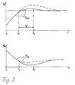
- FIG. 2 is shown in diagram form in accordance with an example of the operation of the method Fig. 1 illustrates, wherein in the upper diagram the actual velocity v is a function of the time t and the lower chart synchronously the time course of the engine torque M m is shown.
- the vehicle speed control is active with an acceleration control phase, since the actual speed v ist is below a speed control interval for speed control phases, the lower end value of the interval v soll -v G of a predetermined distance value v G below the desired target speed v should lie.
- the acceleration control phase the actual velocity v is increased quickly to v in the direction of the target speed.
- V Intervallendwert V -v to G of the velocity control interval is switched so that the vehicle speed control from the previous acceleration to a speed control phase.
- the lower diagram of FIG. 2 shows the influence of the slope-specific speed control parameter set used at the beginning of the speed control phase on the engine torque M m , as represented by the solid line, in comparison to the conventional immediate use of the standard speed control parameter set.
- the engine torque M m then gradually increases to a value suitable for further speed control using the standard speed control parameter set.
- the period of time t d in which the speed controller uses the slope-adjusted control parameter set is expediently chosen so that the speed controller has reduced the engine torque in a steady manner until the time t 2 of the changeover to the standard speed control parameter set so that the gradient-related excess acceleration at least largely is dismantled, so that the changeover to the standard speed control parameter set can be carried out smoothly without disturbing acceleration jerk effects.
Landscapes
- Engineering & Computer Science (AREA)
- Chemical & Material Sciences (AREA)
- Combustion & Propulsion (AREA)
- Transportation (AREA)
- Mechanical Engineering (AREA)
- Controls For Constant Speed Travelling (AREA)
- Control Of Vehicle Engines Or Engines For Specific Uses (AREA)
- Electrical Control Of Air Or Fuel Supplied To Internal-Combustion Engine (AREA)
- Feedback Control In General (AREA)
- Control Of Driving Devices And Active Controlling Of Vehicle (AREA)
- Regulating Braking Force (AREA)
Applications Claiming Priority (2)
| Application Number | Priority Date | Filing Date | Title |
|---|---|---|---|
| DE19858294A DE19858294C2 (de) | 1998-12-17 | 1998-12-17 | Verfahren zur Fahrgeschwindigkeitsregelung eines Kraftfahrzeuges |
| DE19858294 | 1998-12-17 |
Publications (3)
| Publication Number | Publication Date |
|---|---|
| EP1010567A2 true EP1010567A2 (fr) | 2000-06-21 |
| EP1010567A3 EP1010567A3 (fr) | 2001-06-20 |
| EP1010567B1 EP1010567B1 (fr) | 2004-02-25 |
Family
ID=7891447
Family Applications (1)
| Application Number | Title | Priority Date | Filing Date |
|---|---|---|---|
| EP99122601A Expired - Lifetime EP1010567B1 (fr) | 1998-12-17 | 1999-11-13 | Méthode pour la régulation de la vitesse d'un véhicule |
Country Status (4)
| Country | Link |
|---|---|
| US (1) | US6266604B1 (fr) |
| EP (1) | EP1010567B1 (fr) |
| JP (1) | JP2000185576A (fr) |
| DE (1) | DE19858294C2 (fr) |
Cited By (3)
| Publication number | Priority date | Publication date | Assignee | Title |
|---|---|---|---|---|
| WO2014027071A1 (fr) * | 2012-08-16 | 2014-02-20 | Jaguar Land Rover Limited | Procédé et système de régulation de vitesse de véhicule à compensation de force extérieure |
| WO2016174212A3 (fr) * | 2015-04-29 | 2016-12-08 | Jaguar Land Rover Limited | Améliorations de commande de vitesse de véhicule |
| WO2016174211A3 (fr) * | 2015-04-29 | 2016-12-08 | Jaguar Land Rover Limited | Améliorations de commande de vitesse de véhicule |
Families Citing this family (10)
| Publication number | Priority date | Publication date | Assignee | Title |
|---|---|---|---|---|
| DE10210572A1 (de) * | 2002-03-11 | 2003-10-02 | Delphi Tech Inc | Verfahren zur Regelung der Geschwindigkeit eines Kraftfahrzeugs |
| FR2847639B1 (fr) * | 2002-11-21 | 2005-02-04 | Renault Sa | Procede de commande d'une transmission automatique d'un vehicule en situation de descente |
| JP4938542B2 (ja) * | 2007-04-27 | 2012-05-23 | トヨタ自動車株式会社 | 車両の車速制御装置 |
| CN102341287B (zh) * | 2009-03-06 | 2014-06-18 | 丰田自动车株式会社 | 车辆行驶控制装置 |
| CN104583039B (zh) * | 2012-08-16 | 2019-05-17 | 捷豹路虎有限公司 | 用于控制车辆速度以提高乘员舒适度的系统和方法 |
| GB201304781D0 (en) * | 2013-03-15 | 2013-05-01 | Jaguar Land Rover Ltd | Vehicle speed control system and method |
| GB2519533B (en) * | 2013-10-23 | 2018-04-04 | Jaguar Land Rover Ltd | Vehicle speed control system |
| GB2523195B (en) | 2014-02-18 | 2017-10-25 | Jaguar Land Rover Ltd | Control system and method |
| JP6464702B2 (ja) * | 2014-11-28 | 2019-02-06 | 株式会社アドヴィックス | 車両の運転支援装置 |
| JP7169151B2 (ja) * | 2018-10-18 | 2022-11-10 | 日立Astemo株式会社 | 車両制御装置 |
Citations (3)
| Publication number | Priority date | Publication date | Assignee | Title |
|---|---|---|---|---|
| WO1993002885A1 (fr) | 1991-08-09 | 1993-02-18 | Ford Motor Company Limited | Systeme de regulation de vitesse a gains variables associes aux erreurs de vitesse |
| DE4443219C1 (de) | 1994-12-05 | 1996-05-15 | Daimler Benz Ag | Tempomat-Fahrgeschwindigkeitsregeleinrichtung mit regelschwingungsbeeinflussenden Mitteln |
| DE19508492A1 (de) | 1995-03-09 | 1996-09-12 | Bayerische Park Und Lagersyste | Fördervorrichtung |
Family Cites Families (12)
| Publication number | Priority date | Publication date | Assignee | Title |
|---|---|---|---|---|
| US1307038A (en) | 1919-06-17 | Baxteb h | ||
| US1307039A (en) | 1919-06-17 | casler | ||
| DE6920809U (de) * | 1969-05-21 | 1969-11-20 | Waldhof Zellstoff Fab | Prismenfoermige verpackung |
| DE3523352C2 (de) * | 1984-07-27 | 1997-07-03 | Volkswagen Ag | Verfahren zum Regeln der Fahrgeschwindigkeit eines Kraftfahrzeuges, insbesondere eines Kraftfahrzeuges mit Verbrennungsmotor |
| US4736813A (en) * | 1985-04-16 | 1988-04-12 | Mazda Motor Corporation | Cruise control system for vehicle |
| JPH07108622B2 (ja) * | 1986-08-28 | 1995-11-22 | 日産自動車株式会社 | 車両用定速走行装置 |
| JP2887948B2 (ja) * | 1991-06-26 | 1999-05-10 | 株式会社デンソー | 車両用速度制御装置 |
| GB2265994B (en) * | 1992-04-09 | 1995-09-06 | Toyota Motor Co Ltd | Engine control apparatus |
| JP2964200B2 (ja) * | 1992-12-25 | 1999-10-18 | 株式会社ゼクセル | 車両のエンジン出力制御装置 |
| DE4434022C2 (de) * | 1994-09-23 | 1999-11-11 | Daimler Chrysler Ag | Verfahren und Vorrichtung zur Geschwindigkeitsbegrenzung eines Kraftfahrzeuges |
| DE19509492C2 (de) * | 1995-03-16 | 1998-08-27 | Daimler Benz Ag | Verfahren und Vorrichtung zur Geschwindigkeitsbegrenzung eines Kraftfahrzeuges |
| DE19547716B4 (de) * | 1995-12-20 | 2008-12-24 | Robert Bosch Gmbh | Verfahren und Vorrichtung zum Regeln bzw. Begrenzen der Geschwindigkeit eines Fahrzeugs |
-
1998
- 1998-12-17 DE DE19858294A patent/DE19858294C2/de not_active Expired - Fee Related
-
1999
- 1999-11-13 EP EP99122601A patent/EP1010567B1/fr not_active Expired - Lifetime
- 1999-12-13 US US09/458,522 patent/US6266604B1/en not_active Expired - Lifetime
- 1999-12-14 JP JP11376565A patent/JP2000185576A/ja active Pending
Patent Citations (3)
| Publication number | Priority date | Publication date | Assignee | Title |
|---|---|---|---|---|
| WO1993002885A1 (fr) | 1991-08-09 | 1993-02-18 | Ford Motor Company Limited | Systeme de regulation de vitesse a gains variables associes aux erreurs de vitesse |
| DE4443219C1 (de) | 1994-12-05 | 1996-05-15 | Daimler Benz Ag | Tempomat-Fahrgeschwindigkeitsregeleinrichtung mit regelschwingungsbeeinflussenden Mitteln |
| DE19508492A1 (de) | 1995-03-09 | 1996-09-12 | Bayerische Park Und Lagersyste | Fördervorrichtung |
Cited By (7)
| Publication number | Priority date | Publication date | Assignee | Title |
|---|---|---|---|---|
| WO2014027071A1 (fr) * | 2012-08-16 | 2014-02-20 | Jaguar Land Rover Limited | Procédé et système de régulation de vitesse de véhicule à compensation de force extérieure |
| CN104583031A (zh) * | 2012-08-16 | 2015-04-29 | 捷豹路虎有限公司 | 具有外力补偿的车辆速度控制系统和方法 |
| US9630623B2 (en) | 2012-08-16 | 2017-04-25 | Jaguar Land Rover Limited | Vehicle speed control system and method with external force compensation |
| WO2016174212A3 (fr) * | 2015-04-29 | 2016-12-08 | Jaguar Land Rover Limited | Améliorations de commande de vitesse de véhicule |
| WO2016174211A3 (fr) * | 2015-04-29 | 2016-12-08 | Jaguar Land Rover Limited | Améliorations de commande de vitesse de véhicule |
| US10421455B2 (en) | 2015-04-29 | 2019-09-24 | Jaguar Land Rover Limted | Vehicle speed control |
| US10604152B2 (en) | 2015-04-29 | 2020-03-31 | Jaguar Land Rover Limited | Vehicle speed control |
Also Published As
| Publication number | Publication date |
|---|---|
| DE19858294A1 (de) | 2000-07-06 |
| DE19858294C2 (de) | 2000-11-02 |
| US6266604B1 (en) | 2001-07-24 |
| JP2000185576A (ja) | 2000-07-04 |
| EP1010567B1 (fr) | 2004-02-25 |
| EP1010567A3 (fr) | 2001-06-20 |
Similar Documents
| Publication | Publication Date | Title |
|---|---|---|
| DE3930911C2 (de) | Fahrgeschwindigkeitsregler für ein Kraftfahrzeug | |
| EP0278232B1 (fr) | Procédé pour influencer la vitesse de déplacement d'un véhicule automobile et dispositif pour l'exécution du procédé | |
| DE4328747A1 (de) | Konstantgeschwindigkeits-Fahrtsteuerungsgerät | |
| DE19514023A1 (de) | Verfahren und Vorrichtung zur Geschwindigkeits- und Abstandsregelung für ein Kraftfahrzeug | |
| EP0838363A2 (fr) | Méthode et dispositif pour régler la vitesse de déplacement d'un véhicule automobile | |
| DE3434793C2 (de) | Verfahren und Vorrichtung zum ruckarmen Anhalten eines Objekts | |
| DE3721605A1 (de) | Steuerungssystem fuer verbrennungsmotoren | |
| WO1994002346A1 (fr) | Dispositif de commande et de reglage d'un groupe propulseur de vehicule | |
| DE4021810A1 (de) | Antriebsschlupf-regelsystem | |
| DE19624615A1 (de) | Verfahren zur Abstandsregelung für ein Kraftfahrzeug | |
| DE19627727A1 (de) | Verfahren und Vorrichtung zur Steuerung der Geschwindigkeit eines Fahrzeugs | |
| EP1010567B1 (fr) | Méthode pour la régulation de la vitesse d'un véhicule | |
| WO2006111128A1 (fr) | Véhicule à moteur à fonctionnement régulé par la consommation de carburant | |
| DE2748863A1 (de) | Verfahren und vorrichtung zum verhindern des blockierens eines fahrzeugrades auf einer fahrbahn beim bremsen | |
| EP0069922B1 (fr) | Procédé de commande de boîtes de vitesses automatiques dans des véhicules automobiles | |
| DE2712327A1 (de) | Verfahren zur selbsttaetigen regelung von kraftfahrzeugen | |
| DE102016213031A1 (de) | Verfahren zum ruckfreien Stoppen eines Kraftfahrzeugs | |
| DE19502954B4 (de) | Verfahren zur Geschwindigkeitsregelung eines Kraftfahrzeuges | |
| DE19611502B4 (de) | Verfahren und Vorrichtung zur Steuerung der Fahrgeschwindigkeit eines Fahrzeugs | |
| DE4237878A1 (de) | Verfahren zur Regelung des Schaltkomforts bei Fahrzeugen mit automatischem Getriebe | |
| DE3028601C2 (de) | Anordnung zur Regelung der Geschwindigkeit eines Motorfahrzeugs | |
| DE19611840A1 (de) | System zur Bestimmung der Übersetzungsänderungen bei einem Automatikgetriebe | |
| DE19833838A1 (de) | Verfahren und Vorrichtung zur Steuerung der Geschwindigkeit eines Fahrzeugs | |
| DE1438816C3 (de) | Geschwindigkeitsregeleinrichtung für elektrische Triebfahrzeuge | |
| DE19549224A1 (de) | Verfahren und Vorrichtung zur Regelung bzw. Begrenzung der Geschwindigkeit eines Fahrzeugs |
Legal Events
| Date | Code | Title | Description |
|---|---|---|---|
| PUAI | Public reference made under article 153(3) epc to a published international application that has entered the european phase |
Free format text: ORIGINAL CODE: 0009012 |
|
| AK | Designated contracting states |
Kind code of ref document: A2 Designated state(s): FR GB IT SE |
|
| AX | Request for extension of the european patent |
Free format text: AL;LT;LV;MK;RO;SI |
|
| PUAL | Search report despatched |
Free format text: ORIGINAL CODE: 0009013 |
|
| AK | Designated contracting states |
Kind code of ref document: A3 Designated state(s): AT BE CH CY DE DK ES FI FR GB GR IE IT LI LU MC NL PT SE |
|
| AX | Request for extension of the european patent |
Free format text: AL;LT;LV;MK;RO;SI |
|
| 17P | Request for examination filed |
Effective date: 20010602 |
|
| AKX | Designation fees paid |
Free format text: FR GB IT SE |
|
| REG | Reference to a national code |
Ref country code: DE Ref legal event code: 8566 |
|
| 17Q | First examination report despatched |
Effective date: 20020903 |
|
| GRAP | Despatch of communication of intention to grant a patent |
Free format text: ORIGINAL CODE: EPIDOSNIGR1 |
|
| GRAS | Grant fee paid |
Free format text: ORIGINAL CODE: EPIDOSNIGR3 |
|
| GRAA | (expected) grant |
Free format text: ORIGINAL CODE: 0009210 |
|
| AK | Designated contracting states |
Kind code of ref document: B1 Designated state(s): FR GB IT SE |
|
| REG | Reference to a national code |
Ref country code: GB Ref legal event code: FG4D Free format text: NOT ENGLISH |
|
| GBT | Gb: translation of ep patent filed (gb section 77(6)(a)/1977) |
Effective date: 20040414 |
|
| REG | Reference to a national code |
Ref country code: SE Ref legal event code: TRGR |
|
| PGFP | Annual fee paid to national office [announced via postgrant information from national office to epo] |
Ref country code: GB Payment date: 20041102 Year of fee payment: 6 |
|
| PGFP | Annual fee paid to national office [announced via postgrant information from national office to epo] |
Ref country code: SE Payment date: 20041109 Year of fee payment: 6 |
|
| ET | Fr: translation filed | ||
| PGFP | Annual fee paid to national office [announced via postgrant information from national office to epo] |
Ref country code: FR Payment date: 20041112 Year of fee payment: 6 |
|
| PLBE | No opposition filed within time limit |
Free format text: ORIGINAL CODE: 0009261 |
|
| STAA | Information on the status of an ep patent application or granted ep patent |
Free format text: STATUS: NO OPPOSITION FILED WITHIN TIME LIMIT |
|
| 26N | No opposition filed |
Effective date: 20041126 |
|
| PG25 | Lapsed in a contracting state [announced via postgrant information from national office to epo] |
Ref country code: IT Free format text: LAPSE BECAUSE OF NON-PAYMENT OF DUE FEES;WARNING: LAPSES OF ITALIAN PATENTS WITH EFFECTIVE DATE BEFORE 2007 MAY HAVE OCCURRED AT ANY TIME BEFORE 2007. THE CORRECT EFFECTIVE DATE MAY BE DIFFERENT FROM THE ONE RECORDED. Effective date: 20051113 Ref country code: GB Free format text: LAPSE BECAUSE OF NON-PAYMENT OF DUE FEES Effective date: 20051113 |
|
| PG25 | Lapsed in a contracting state [announced via postgrant information from national office to epo] |
Ref country code: SE Free format text: LAPSE BECAUSE OF NON-PAYMENT OF DUE FEES Effective date: 20051114 |
|
| EUG | Se: european patent has lapsed | ||
| GBPC | Gb: european patent ceased through non-payment of renewal fee |
Effective date: 20051113 |
|
| PG25 | Lapsed in a contracting state [announced via postgrant information from national office to epo] |
Ref country code: FR Free format text: LAPSE BECAUSE OF NON-PAYMENT OF DUE FEES Effective date: 20060731 |
|
| REG | Reference to a national code |
Ref country code: FR Ref legal event code: ST Effective date: 20060731 |