EP1004486A2 - Schwenkscheibenlenkschloss mit Sicherungsbuchse - Google Patents
Schwenkscheibenlenkschloss mit Sicherungsbuchse Download PDFInfo
- Publication number
- EP1004486A2 EP1004486A2 EP99123502A EP99123502A EP1004486A2 EP 1004486 A2 EP1004486 A2 EP 1004486A2 EP 99123502 A EP99123502 A EP 99123502A EP 99123502 A EP99123502 A EP 99123502A EP 1004486 A2 EP1004486 A2 EP 1004486A2
- Authority
- EP
- European Patent Office
- Prior art keywords
- control cam
- swivel plate
- steering lock
- locking
- lock according
- Prior art date
- Legal status (The legal status is an assumption and is not a legal conclusion. Google has not performed a legal analysis and makes no representation as to the accuracy of the status listed.)
- Withdrawn
Links
- 230000033001 locomotion Effects 0.000 claims description 11
- 230000000903 blocking effect Effects 0.000 claims 1
- 238000006073 displacement reaction Methods 0.000 claims 1
- 238000004519 manufacturing process Methods 0.000 description 4
- 230000002349 favourable effect Effects 0.000 description 3
- 238000010276 construction Methods 0.000 description 2
- 238000003780 insertion Methods 0.000 description 2
- 230000037431 insertion Effects 0.000 description 2
- KJFBVJALEQWJBS-XUXIUFHCSA-N maribavir Chemical compound CC(C)NC1=NC2=CC(Cl)=C(Cl)C=C2N1[C@H]1O[C@@H](CO)[C@H](O)[C@@H]1O KJFBVJALEQWJBS-XUXIUFHCSA-N 0.000 description 2
- 230000005540 biological transmission Effects 0.000 description 1
- 238000009434 installation Methods 0.000 description 1
- 230000036316 preload Effects 0.000 description 1
- 239000007787 solid Substances 0.000 description 1
Images


Classifications
-
- B—PERFORMING OPERATIONS; TRANSPORTING
- B60—VEHICLES IN GENERAL
- B60R—VEHICLES, VEHICLE FITTINGS, OR VEHICLE PARTS, NOT OTHERWISE PROVIDED FOR
- B60R25/00—Fittings or systems for preventing or indicating unauthorised use or theft of vehicles
- B60R25/01—Fittings or systems for preventing or indicating unauthorised use or theft of vehicles operating on vehicle systems or fittings, e.g. on doors, seats or windscreens
- B60R25/02—Fittings or systems for preventing or indicating unauthorised use or theft of vehicles operating on vehicle systems or fittings, e.g. on doors, seats or windscreens operating on the steering mechanism
- B60R25/021—Fittings or systems for preventing or indicating unauthorised use or theft of vehicles operating on vehicle systems or fittings, e.g. on doors, seats or windscreens operating on the steering mechanism restraining movement of the steering column or steering wheel hub, e.g. restraining means controlled by ignition switch
- B60R25/0211—Fittings or systems for preventing or indicating unauthorised use or theft of vehicles operating on vehicle systems or fittings, e.g. on doors, seats or windscreens operating on the steering mechanism restraining movement of the steering column or steering wheel hub, e.g. restraining means controlled by ignition switch comprising a locking member radially and linearly moved towards the steering column
- B60R25/02115—Fittings or systems for preventing or indicating unauthorised use or theft of vehicles operating on vehicle systems or fittings, e.g. on doors, seats or windscreens operating on the steering mechanism restraining movement of the steering column or steering wheel hub, e.g. restraining means controlled by ignition switch comprising a locking member radially and linearly moved towards the steering column key actuated
- B60R25/02126—Fittings or systems for preventing or indicating unauthorised use or theft of vehicles operating on vehicle systems or fittings, e.g. on doors, seats or windscreens operating on the steering mechanism restraining movement of the steering column or steering wheel hub, e.g. restraining means controlled by ignition switch comprising a locking member radially and linearly moved towards the steering column key actuated with linear bolt motion perpendicular to the lock axis
Definitions
- the invention relates to a steering lock for a motor vehicle with a lock cylinder, the cylinder core with its twisted inner end on control cam, whereby by means of Control cam a locking piece perpendicular to the lock axis is movable, the movement in a locking position the steering spindle is blocked.
- the object of the invention is to provide a steering lock, what with a simple mechanical structure an inexpensive Manufacturing and high operational reliability guaranteed.
- a particularly advantageous and robust form of the Steering lock has a swivel plate around it pivot axis extending outside the lock axis is pivotable, the lock axis and the pivot axis lie in one plane.
- the distance between the both axes the leverage of the driving cam, which the Apply to the inside of the recess, be optimized.
- the drive cam via a run-up contour on the Inside of the recess acts on the swashplate.
- a locking bush can be moved for the control cam stored in a certain position of the swivel plate can engage in the recess to the swivel plate in secure this position.
- the fuse socket ensures that the steering lock engages without simultaneous removal of the ignition key becomes impossible.
- the simple implementation of this safety function helps also to reduce manufacturing costs and Operational safety of the steering lock.
- the cylindrical locking bush guided in a lock channel which is introduced into the lock housing coaxially with the control cam is.
- the fuse socket is movable guided.
- the fuse socket is through a nose that runs in a groove in the housing, secured against rotation, while the lock cylinder and the control cam in Lock channel are rotatably mounted. It is special advantageous that the fuse socket and control cam in the same machined diameter of the lock housing are stored, so that there is a favorable tolerance chain.
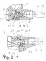
- FIGs 1a and 1b is a steering lock with a solid Lock housing 1 shown, in which the individual parts of the Steering lock are stored.
- the lock housing 1 has one Recess 2 for fastening the lock to the steering column on.
- a lock channel 3 introduced in which a lock cylinder 4 is mounted.
- the Lock cylinder 4 is inserted after key 5 actuated by turning the key.
- the lock cylinder in turn twists one on his with its cylinder core inner end attached control cam 6, with its Point penetrates a hole in the bottom 7 of the lock channel 3 and actuates an electrical switch 8 located behind it.
- the control cam 6 is axial within the lock channel 3 displaceable against the force of one on the bottom 7 of the Lock channel 3 supporting spring 9 slidably.
- the control cam 6 operates one with a drive cam 10 Swivel plate 11.
- the swivel plate 11 has the function a locking bolt and snaps into place with a locking lug 12 Recess of a not shown, in the recess 2 located, steering spindle.
- the swivel plate 11 is in a located in the lock housing 1 groove 13, the is aligned parallel to the steering spindle.
- the swivel plate has one in the area of the lock channel Recess 14 through which the control cam 6 protrudes. It is around an outside of the lock axis Swivel axis 15 pivotable and has the form and function an eccentric.
- the pivoting of the swivel plate 11 happens against the force of a swivel plate 11 acting leaf spring 16.
- the leaf spring 16 provides for the swivel plate 11 in the appropriate position the steering spindle and 5 when the key is removed engages in the groove of the steering spindle and locks it in place.
- the the pivot pin 15 forming the bearing pin simultaneously secures a cover 17 against tampering, which has a side opening of the castle canal.
- the lid 17 is by dowel pins fixes and forms the abutment, which the swash plate 11th leaf spring 16.
- the fuse socket 18 is thus located in the locking position of the steering lock in one by the Spring 19 somewhat preloaded condition, the preload between two sections formed on the control cam 6, namely the driving cam 10 and one Paragraph, happens. With appropriate approval by the Driving cams 10 can secure the bushing 18 into the recess 14 slip in when the swashplate is in the unlocking position.
- the driving cam 10 free the movement of the swivel plate 11. If the key is removed, the spring 9 drives the Control cam 6 in the axial direction from the lock housing 1.
- the drive cam 10 takes the securing sleeve 18 with and leads them out of the recess 14. Since the spring 19 itself also by a corresponding piece in this direction moved, an application of force to the spring 19 is not necessary and the force of the smaller dimension spring 9 is sufficient to disengage the locking bush 18 from the recess 14 to accomplish.
- the key is removed and will the steering spindle moves to the appropriate position, so the swivel plate 11 with its locking lug 12 through Actuation of the leaf spring 16 in the recess of the Engage the steering spindle and block its further movement.
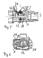
- the embodiment of the steering lock according to Figures 5 and 6 is essentially the same as before described designs.
- the crucial difference is that the housing 1 to the vehicle interior is completely closed and assembly by the Castle channel 3 and through an assembly opening 21 happens.
- the Assembly opening 21 is open to the steering spindle and is after inserting the swivel plate 11 by a pressed closure piece 22 closed.
- the Swivel plate 11 is supported by a leaf spring 23 in Release direction applied.
Landscapes
- Engineering & Computer Science (AREA)
- Mechanical Engineering (AREA)
- Lock And Its Accessories (AREA)
Abstract
Description
- Figur 1
- ein Lenkschloß in sperrender Stellung,
- Figur 2
- ein Lenkschloß nach dem Einführen des Zündschlüssels,
- Figur 3
- ein Lenkschloß in entsperrter Stellung,
- Figur 4
- ein Lenkschloß in entsperrter Stellung in Draufsicht,
- Figur 5
- ein Lenkschloß mit geschlossenem Gehäuse,
- Figur 6
- ein Schnitt durch das Lenkschloß nach Figur 5.
Claims (12)
- Lenkschloß für ein Kraftfahrzeug mit einem Schließzylinder, dessen Zylinderkern mit seinem inneren Ende einen Steuernocken verdreht, wobei mittels des Steuernockens ein Sperrstück senkrecht zur Schloßachse bewegbar ist, das in einer sperrenden Stellung die Bewegung der Lenkspindel blockiert,
dadurch gekennzeichnet, daß das Sperrstück eine Schwenkscheibe (11) ist, die durch den Steuernocken (6) zwischen einer sperrenden und einer entsperrten Stellung verschwenkbar ist, wobei der Steuernocken (6) eine Ausnehmung (14) der Schwenkscheibe (11) durchragt. - Lenkschloß nach Anspruch 1,
dadurch gekennzeichnet, daß die Schwenkscheibe (11) um eine außerhalb der Schloßachse liegende Schwenkachse (15) durch Drehung des Steuernockens (6) verschwenkbar ist, wobei der Steuernocken (6) einen Treibnocken (10) aufweist, mit dem die Schwenkscheibe (11) an der Innenseite der Ausnehmung (14) beaufschlagbar ist. - Lenkschloß nach Anspruch 1 oder 2,
dadurch gekennzeichnet, daß der Steuernocken (11) von einer koaxial zur Schloßachse verschieblichen Sicherungsbuchse (18) umgeben ist, die in der entsperrten Stellung die Ausnehmung (14) der Schwenkscheibe (11) zumindest teilweise durchragt und in dieser Sicherungsstellung ein Verschwenken der Schwenkscheibe (11) blockiert. - Lenkschloß nach Anspruch 3,
dadurch gekennzeichnet, daß die Sicherungsbuchse (18) in einem in das Schloßgehäuse (1) eingebrachten Schloßkanal (3) axial verschieblich geführt ist. - Lenkschloß nach Anspruch 3 oder 4,
dadurch gekennzeichnet, daß die Sicherungsbuchse (18) zwischen dem Zylinderkern (4) und der Schwenkscheibe (11) angeordnet ist. - Lenkschloß nach einem der vorherigen Ansprüche,
dadurch gekennzeichnet, daß die Sicherungsbuchse (18) von einer Feder (19) insbesondere einer Spiralfeder in Richtung der Schwenkscheibe (11) beaufschlagt ist, wobei der Steuernocken (6) das Widerlager der Feder (19) bildet. - Lenkschloß nach einem der vorherigen Ansprüche,
dadurch gekennzeichnet, daß die axialer Verschiebung der in der Sicherungsstellung befindlichen Sicherungsbuchse (18) durch den Treibnocken (10) blockiert wird. - Lenkschloß nach einem der vorherigen Ansprüche,
dadurch gekennzeichnet, daß der Steuernocken (6) durch das Einführen des Zündschlüssels (5) gegen die Kraft einer Feder (9) axial verschieblich ist, wobei mittels der axialen Verschiebung des Steuernockens (6) die Spiralfeder (19) und damit die Sicherungsbuchse (18) vorspannbar ist. - Lenkschloß nach Anspruch 8,
dadurch gekennzeichnet, daß durch Drehen des Zündschlüssels (5) die Schwenkscheibe (11) in die entsperrte Stellung überführbar ist, so daß die Sicherungsbuchse (18) in der Sicherungsstellung einrastet. - Lenkschloß nach einem der vorherigen Ansprüche,
dadurch gekennzeichnet, daß beim Herausziehen des Zündschlüssels (5) die Sicherungsbuchse (18) durch den Treibnocken (10) mitnehmbar und aus der Ausnehmung (14) herausführbar ist. - Lenkschloß nach einem der vorherigen Ansprüche,
dadurch gekennzeichnet, daß die Schwenkscheibe (11) eine Rastnase (12) aufweist, die in der sperrenden Stellung in eine Ausnehmung der Lenkspindel eingreift. - Lenkschloß nach einem der vorherigen Ansprüche,
dadurch gekennzeichnet, daß die Schwenkscheibe (11) gegen die Kraft einer Feder insbesondere einer Blattfeder (16) verschwenkbar ist.
Applications Claiming Priority (2)
| Application Number | Priority Date | Filing Date | Title |
|---|---|---|---|
| DE1998154682 DE19854682A1 (de) | 1998-11-26 | 1998-11-26 | Schwenkscheibenlenkschloß mit Sicherungsbuchse |
| DE19854682 | 1998-11-26 |
Publications (2)
| Publication Number | Publication Date |
|---|---|
| EP1004486A2 true EP1004486A2 (de) | 2000-05-31 |
| EP1004486A3 EP1004486A3 (de) | 2002-06-26 |
Family
ID=7889169
Family Applications (1)
| Application Number | Title | Priority Date | Filing Date |
|---|---|---|---|
| EP99123502A Withdrawn EP1004486A3 (de) | 1998-11-26 | 1999-11-25 | Schwenkscheibenlenkschloss mit Sicherungsbuchse |
Country Status (2)
| Country | Link |
|---|---|
| EP (1) | EP1004486A3 (de) |
| DE (1) | DE19854682A1 (de) |
Families Citing this family (2)
| Publication number | Priority date | Publication date | Assignee | Title |
|---|---|---|---|---|
| DE10246225A1 (de) * | 2002-10-04 | 2004-04-15 | Bayerische Motoren Werke Ag | Kraftfahrzeuglenkeinrichtung |
| JP5114369B2 (ja) * | 2008-11-28 | 2013-01-09 | 株式会社ユーシン | ステアリングロック装置 |
Family Cites Families (6)
| Publication number | Priority date | Publication date | Assignee | Title |
|---|---|---|---|---|
| DE1240423B (de) * | 1962-08-11 | 1967-05-11 | Auto Union Gmbh | Lenkschloss fuer Kraftfahrzeuge |
| DE3213719C2 (de) * | 1982-04-14 | 1984-08-23 | Neiman GmbH, 5657 Haan | Vorrichtung zum Sperren der Drehbewegung einer Lenkspindel eines Kraftfahrzeugs |
| DE3318359C2 (de) * | 1983-05-20 | 1985-11-21 | Hülsbeck & Fürst GmbH & Co KG, 5620 Velbert | Lenk- und Zündschloß für Kraftfahrzeuge |
| DE3611962A1 (de) * | 1986-04-09 | 1987-10-15 | Tibbe Kg | Kraftfahrzeug-lenkschloss |
| GB2298229B (en) * | 1995-02-23 | 1998-01-14 | Valeo Security Systems Ltd | A lock |
| DE19506826C2 (de) * | 1995-02-28 | 2003-12-24 | Valeo Deutschland Gmbh & Co | Lenkschloß |
-
1998
- 1998-11-26 DE DE1998154682 patent/DE19854682A1/de not_active Withdrawn
-
1999
- 1999-11-25 EP EP99123502A patent/EP1004486A3/de not_active Withdrawn
Non-Patent Citations (1)
| Title |
|---|
| None |
Also Published As
| Publication number | Publication date |
|---|---|
| DE19854682A1 (de) | 2000-05-31 |
| EP1004486A3 (de) | 2002-06-26 |
Similar Documents
| Publication | Publication Date | Title |
|---|---|---|
| DE19961975C1 (de) | Verriegelungsvorrichtung | |
| EP0722029B1 (de) | Kraftfahrzeug-Türschloss mit rotorischer Zentralverriegelung | |
| DE69704587T2 (de) | Autotürschloss | |
| DE69922373T2 (de) | Verschlussvorrichtung und haubenschloss für ein fahrzeug mit einer derartigen verschlussvorrichtung | |
| DE3616122C2 (de) | Lenk- und Zündschloß | |
| EP1555363B1 (de) | Betätigungsvorrichtung für Türen oder Klappen an Fahrzeugen | |
| EP1052356B1 (de) | Vorrichtung zum Verschliessen einer Fahrzeugtür | |
| DE19632781A1 (de) | Kraftfahrzeug-Türverschluß mit Zentralverriegelungssystem und Diebstahlsicherungssystem | |
| EP1541789A2 (de) | Kraftfahrzeugschloss, insbesondere für einen Kofferdeckel oder eine Hecktür eines Kraftfahrzeugs | |
| DE10152617A1 (de) | Fahrzeugtürschloss | |
| EP0887240B1 (de) | Verriegelungsvorrichtung für ein Kraftfahrzeug | |
| DE10335311B4 (de) | Lenkschlossvorrichtung | |
| EP3784855B1 (de) | Kraftfahrzeugschloss | |
| DE10301998B4 (de) | Schließhilfe zum Verschließen einer mit einem Türschloß versehenen Fahrzeugtür | |
| DE2632908B2 (de) | Kraftfahrzeug-Lenkschloß | |
| EP1004486A2 (de) | Schwenkscheibenlenkschloss mit Sicherungsbuchse | |
| DE4407912C2 (de) | Elektromechanisches Schloß | |
| DE102022204691B4 (de) | Parksperrenanordnung mit Not-Aktuator mit passiver Beschleunigungskompensation | |
| DE19526660B4 (de) | Elektromechanisches Schloß | |
| EP3899174B1 (de) | Schloss für ein kraftfahrzeug | |
| EP0791707B1 (de) | Kraftfahrzeugschloss | |
| DE3509834C2 (de) | ||
| DE2355922C3 (de) | Kraftfahrzeug-Lenkschloß | |
| DE4233029C2 (de) | Schließzylinder | |
| DE19814002C2 (de) | Kupplung |
Legal Events
| Date | Code | Title | Description |
|---|---|---|---|
| PUAI | Public reference made under article 153(3) epc to a published international application that has entered the european phase |
Free format text: ORIGINAL CODE: 0009012 |
|
| AK | Designated contracting states |
Kind code of ref document: A2 Designated state(s): AT BE CH CY DE DK ES FI FR GB GR IE IT LI LU MC NL PT SE |
|
| AX | Request for extension of the european patent |
Free format text: AL;LT;LV;MK;RO;SI |
|
| PUAL | Search report despatched |
Free format text: ORIGINAL CODE: 0009013 |
|
| AK | Designated contracting states |
Kind code of ref document: A3 Designated state(s): AT BE CH CY DE DK ES FI FR GB GR IE IT LI LU MC NL PT SE |
|
| AX | Request for extension of the european patent |
Free format text: AL;LT;LV;MK;RO;SI |
|
| 17P | Request for examination filed |
Effective date: 20021210 |
|
| AKX | Designation fees paid |
Designated state(s): DE ES FR GB IT |
|
| 17Q | First examination report despatched |
Effective date: 20030303 |
|
| RAP1 | Party data changed (applicant data changed or rights of an application transferred) |
Owner name: VALEO SICHERHEITSSYSTEME GMBH |
|
| GRAP | Despatch of communication of intention to grant a patent |
Free format text: ORIGINAL CODE: EPIDOSNIGR1 |
|
| STAA | Information on the status of an ep patent application or granted ep patent |
Free format text: STATUS: THE APPLICATION IS DEEMED TO BE WITHDRAWN |
|
| 18D | Application deemed to be withdrawn |
Effective date: 20050921 |