EP0992288A2 - Pipettenspitzenabwurfeinrichtung - Google Patents
Pipettenspitzenabwurfeinrichtung Download PDFInfo
- Publication number
- EP0992288A2 EP0992288A2 EP99114892A EP99114892A EP0992288A2 EP 0992288 A2 EP0992288 A2 EP 0992288A2 EP 99114892 A EP99114892 A EP 99114892A EP 99114892 A EP99114892 A EP 99114892A EP 0992288 A2 EP0992288 A2 EP 0992288A2
- Authority
- EP
- European Patent Office
- Prior art keywords
- pipetting system
- pipetting
- drive
- ejection
- pipette tip
- Prior art date
- Legal status (The legal status is an assumption and is not a legal conclusion. Google has not performed a legal analysis and makes no representation as to the accuracy of the status listed.)
- Granted
Links
Images


Classifications
-
- B—PERFORMING OPERATIONS; TRANSPORTING
- B01—PHYSICAL OR CHEMICAL PROCESSES OR APPARATUS IN GENERAL
- B01L—CHEMICAL OR PHYSICAL LABORATORY APPARATUS FOR GENERAL USE
- B01L3/00—Containers or dishes for laboratory use, e.g. laboratory glassware; Droppers
- B01L3/02—Burettes; Pipettes
- B01L3/0275—Interchangeable or disposable dispensing tips
- B01L3/0279—Interchangeable or disposable dispensing tips co-operating with positive ejection means
Definitions
- the invention relates to a pipetting system with a pipetting device and at least one pipette tip releasably attached thereto.
- Such pipetting systems are used primarily in the laboratory for dosing liquid quantities used. These are sucked into and out of pipette tips pushed out.
- pistons are usually slidably arranged in a cylinder.
- the piston and cylinder are in the pipetting device integrates and communicates with the pipette tip so that the dosage of the liquid is mediated by an air cushion.
- direct displacement systems are pistons and cylinder integrated into the tip and act directly on the liquid that is sucked in on.
- Such pipette tips are also referred to as syringes.
- Pistonless Systems can in particular have a pipette tip with a balloon-like end section have, which expands for sucking in liquid and for expelling is compressed.
- the pipette tip is releasably connected to the pipetting device so that it can be exchanged for a fresh pipette tip after use, whereby contamination can be avoided in subsequent doses.
- Disposable pipette tips are inexpensive plastic available.
- the pipetting devices have a fastening attachment for fastening Pipette tips.
- This is usually a conical projection on which a pipette tip is clamped with a conical receptacle. This can be done without touching the Pipette tip by pushing the fastening attachment onto a pipette tip take place, which is available in a holder.
- pipetting devices are often equipped with a discharge device which is assigned to the upper edge region of the pipette tip with a discharge sleeve and can be actuated at a discharge button.
- a discharge device which is assigned to the upper edge region of the pipette tip with a discharge sleeve and can be actuated at a discharge button.
- a pipette with a tip remover is known from EP 0 566 039 B1 to facilitate use by reducing the dropping force Has lever mechanism.
- This lever mechanism jumps sideways from one Pipette housing in front and must be pressed manually. He can have a gear on that an actuating arm for the pipette tip rotatable in a vertical plane is articulated. Furthermore, the inner flank of the gear meshes with a rack the side of the elongated case.
- On the outside of the operating arm is on a hollow push rod is arranged on the side of the housing, which is threaded combs on the inside with the outside of the gear.
- the invention is based on the object of having a pipetting system to create a dropping device that other than the aforementioned Translation ratios and constructive simplifications enabled.
- the pipetting system according to the invention is an alternative to the known pipette with tip remover, due to the traction mechanism, pressure transmission or articulated gearbox both the known transmission ratio and others Ratios and thus increased freedom of design and expanded Possible applications. Are also in an inventive Pipetting system transmission ratios possible during a tip ejection vary.
- the pipetting system also opens up the possibility structural simplifications.
- the drive device and the Ejection element have overlapping end sections and the gearbox one at the end portion of the discharge element rotatably mounted guide roller and a Have rope that is fixed at one end with respect to the fastener and at the other end is fixed to the end section of the drive device.
- P refers a drive rod and the ejection element are aligned parallel to each other. With the essentially axial drive movement over a certain one The ejection element only moves half of this way. It says however, a force is available on the ejection element for releasing the pipette tip, which is about twice as large as that applied for the drive movement Force.
- Other gear ratios can be achieved if more than one Deflection rollers are mounted on the discharge element. This gear enables structurally particularly simple solutions.
- the transmission has one with the drive device connected first piston which is displaceable in a first cylinder is and a second piston connected to the ejection element, which in a second cylinder is displaceable, the two cylinders communicating with one another, this communicating cylinder system is sealed off from the environment and is filled with hydraulic fluid and the first piston has a smaller cross-sectional area than the second piston.
- the first piston over a certain distance a displacement of the second piston over a shorter distance, the ratio of the distances being inversely proportional to the ratio of the cross-sectional areas of the two pistons.
- the ratio of these forces being proportional to the ratio of the cross-sectional areas of the two pistons.
- the transmission has one with the Drive device connected first bellows and one with the discharge element connected second bellows, the bellows communicating with each other are connected with this communicating bellows system Hydraulic fluid is filled and the first fold has a smaller cross section than the second bellows.
- the gearbox has a first articulated rod on, which is articulated to the drive device and a second joint rod, the is articulated to the ejection element, the two joint rods at the other end are hinged together and in the articulation area along a with respect to the Fastener are fixed guide performed a first guide section has, the distance from a common axis of the drive movement and the discharge element in the direction from the drive device to Throwing element increases and which is arranged so that the articulation area movable along this first guide section when a pipette tip is released is.
- the articulation area of the two joint rods reaches the area of the first one Guide section, in which it is laterally from the common axis of the drive movement and evades the release element.
- the drive movement a larger path than the ejection element and on the other hand provided a greater force on the ejection element than on the Drive rod is exercised.
- This version also enables extensive Variability of the transmission ratio and even variable transmission ratios during a dropping process. Here too are very simple constructive designs possible.
- the discharge element can be a discharge rod. This can in turn with at least one further element of a discharge device be connected.
- the fastener can be a mounting approach, a Attachment receptacle or the like.
- the invention can be used in all types of pipetting systems, in particular with piston stroke and direct displacement systems, with single stroke and Dispenser systems, for manual and stationary systems, for manual and motor-driven systems and one-hand and multi-channel systems.
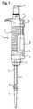
- a hand-held pipetting system has a hand-held pipetting device 1 with a housing 2 and a housing shaft 3, the bottom End has a mounting boss in the form of a plug-on cone 4.
- a pipette tip 5 is placed on the plug-on cone 4 so that it clamps, however can be pushed off by the plug-on cone 4.
- An actuation button 6 protrudes out of the housing 2 at the top.
- the actuating button 6 By pressing in axially the actuating button 6 can be in the housing 2 between two stops a piston can be moved in a cylinder. The cylinder is over a channel connected to an opening at the lower end of the plug-on cone 4. By shift an air column of the piston is moved in the channel. After pressing the Piston 6 can return to its starting position with spring support, the air column can suck liquid into the pipette tip 5. Again Pressing the actuating button 6 causes the liquid to be expelled from the Pipette tip 5.
- the Pipetting device For a subsequent detachment of the pipette tip 5 from the plug-on cone 4, the Pipetting device a discharge device 7. This has a sliding on the ejection sleeve 8 arranged on the housing shaft 3 with a lateral projection 9 at the top inside the housing 2.
- Drive rod 10 which can be actuated by means of a release button 11, which above the housing 2 protrudes.
- the lower end of the drive rod 10 is over a Gear 12 connected to the upper end of a discharge rod 13, which also is parallel to the housing shaft 3.
- the lower end of the ejector rod 13 is again assigned to the lateral projection 9 of the discharge sleeve 8.
- the gear 12 is a traction, pressure or articulated gear. It has a Reduction.
- the displacement path is when the ejection device 7 is actuated the release button 11 larger than the displacement of the discharge sleeve 8, but exceeds that of the discharge sleeve 8 on the upper edge of the pipette tip 5 force exerted the force exerted on the release button 11. Stuck Pipette tips 5 can thus be detached from the pipetting device 1 more easily.
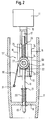
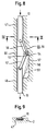
- FIGS. 2 and 3 show an embodiment of the transmission as a traction mechanism transmission 12 '.
- a guide block 14 at the lower end portion of the drive rod 10, in which an axially directed guide groove 15 is formed, which has a lateral opening 16 has.
- the drive rod 10 adjoins the guide block 14 an axial guide bore 17.
- the ejector rod 13 is guided through a transverse housing wall 18.
- the Ejector rod 13 carries a ring 19 below the housing wall 18, which it against pulling up ensures.
- a compression spring is located above the housing wall 18 21 guided on the discharge rod 13, which is at one end on the housing wall 18 and at the other end is supported on a further ring 21, which is on the discharge rod 13 sits.
- the ejector rod 13 carries a bearing block 22 is pushed onto the discharge rod 13 and by means of rings 23, 24 on the discharge rod 13 secured.
- the discharge rod 13 projects with its upper end into the Guide bore 17 into it and the bearing block 22 is in the guide groove 15 of the Guide block 14 out.
- Above the bearing block 22 is on the Ejection rod 13 is guided by a compression spring 25, which ends at the ring 24 and at the other end at a step 26 between the guide groove 15 and the guide bore 17 supports.
- a deflection roller 28 On a bearing pin 27 of the bearing block 22 protruding from the opening 16 a deflection roller 28 is mounted.
- the deflection roller 28 has a groove 29 on the circumference.
- a rope 30 is laid around the deflection roller 28 and guided in the groove 29.
- the rope 30 can in particular be a steel or wire rope. It runs about halfway through of the circumference of the deflection roller 28. At one end it is below the bearing block 22 in the housing 2 and thus with respect to a plug-on cone 4 for a pipette tip 5 fixed. At the other end, it is below the deflection roller 28 at 32 on the guide block 14 set.
- the attachment to the housing 2 takes place, for example, by means of a loop that opens a cone sits.
- the attachment to the guide block 14 takes place, for example by means of a rope-proof ball or another thickening, which from the side in a receptacle is pushed, which has a passage for the rope 30.
- the bearing block 22 has a ring 33 concentric with the bearing journal 27, which secures the deflection roller 28 with a bead 34 on the inner circumference and the rope 30 prevents slipping out of the groove 29.
- the wreath 33 has Through bores through which the ends of the rope 30 are guided to the outside are.
- the gear 12 When the release button 11 is not actuated, the gear 12 'takes the arrangement shown on. If the release button 11 is actuated, the drive rod 10 pulls with the Guide block 14 the attached end of the rope 30 down. Doing so the rope 30 over the pulley 28 and at the same time the pulley 28 and thus the bearing block 22 and the ejector rod 13 are pulled down.
- This traction mechanism 12 'causes the ejector rod 13 to move an ejection distance which is only half as large as the displacement distance of the drive rod 10.
- the ejection force that can be exerted by the ejection rod 13 is twice as large as the force applied to the release button 11.
- the lower end of the drop bar 13 can therefore directly or via a discharge sleeve 8 an increased force on a pipette tip 5 exercise.
- the spring 20 presses the traction mechanism gear 12 'back to the drawn starting position.
- the spring 25 pushes the drive rod 10 with respect to the ejection rod 13 in the starting position and is the same thus the differences in the displacements of drive rod 10 and Throwing rod 13 so that the rope 30 is kept under tension.
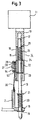
- the pressure medium piston transmission 12 ′′ shown in FIG. 4 can also be in one Pipetting system according to FIG. 1 are used.
- the drive rod is 10 connected to a first piston 33. This is axially displaceable in arranged in a cylinder 34.
- the drive rod 10, which is also the drive rod of the piston 33 is sealed by the upper opening of the cylinder 34 guided.
- an O-ring 35 is supported on an inner shoulder of the cylinder 34 and pressed between the cylinder 34 and the ejector rod 10 by means of a screw ring 36, similar to a stuffing box seal.
- the maximum diameter D 1 of the piston 32 is significantly smaller than the inside diameter of the cylinder 34.
- the spring guided on the discharge rod 13 is supported at one end on the transverse one Housing wall 18 and at the other end on a shoulder 40 on the underside of the piston 37.
- Hydraulic fluid 41 filled.
- the transmission 12 ′′ is shown in an unactuated arrangement.
- the ejection button 11 is pressed so that the piston 33 dips deeper into the cylinder 34.
- hydraulic fluid is displaced and the piston 37 is moved downward against the action of the spring 20, so that the ejection rod 13 takes the ejection sleeve 8 with it and ultimately pushes the pipette tip 5 off the plug-on cone 4.
- the distance traveled by the drive rod 10 is less than the distance covered by the ejection rod 13 and the ejection force (F 2 ) exerted by the ejection rod 13 on the ejection sleeve 8 is greater than the force acting on the ejection button 11 (F 1 ), since the Diameter D 2 of the piston 37 exceeds the diameter D 1 of the piston 33.
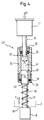
- a pipette system according to FIG. 1 can also be equipped with a pressure medium bellows gear 12 '' 'according to FIGS. 5 and 6.
- This has a first one Bellows 42, which is connected at the end to the drive rod 10, so that it from this can be compressed. It also has a second bellows 43 which is connected at the front to the ejector rod 13 so that it can be unfolded axially shifts.
- the two bellows 42, 43 connected to each other via a short hose section 44, so that their Communicate interiors with each other. In this area runs between the Bellows 42, 43 a radially directed groove 45 in which a transverse Housing wall 18 engages. This has a laterally open slot 46 for insertion of the hose section 44.
- the bellows 42, 43 and the hose section 44 are filled with a hydraulic fluid 41 or another suitable fluid. They have a circular cross section, and the bellows 42 can have a diameter (D1) that is approximately half that of the bellows 43 (D 2 ).
- the bellows 42, 43 can be made from an elastic material, that they have the unconcerned endeavor to take the initial form shown in FIG to assume. However, it is also possible to use an additional form To achieve spring device.
- the bellows 42 can be compressed by moving the drive rod 10 in the direction of the arrow, the hydraulic fluid 41 being displaced into the bellows 43 and expanding it.
- the arrangement according to FIG. 6 is achieved in which the bellows 42 is maximally compressed and the bellows 43 is maximally expanded.
- the compression path Y of the bellows 42 is significantly greater than the expansion path Z of the bellows 43.
- the bellows 43 presses with a significantly greater ejection force (F 2 ) on the ejection rod 13 than is introduced into the bellows 42 via the drive rod 10 (F 1 ).
- the pipetting system according to FIG. 1 can advantageously also be equipped with an articulated gear 12 IV according to FIG. 7.
- the drive rod 10 and the ejector rod 13 are guided coaxially in axial guides 47, 48 of the housing.
- a first joint rod 50, 50 'and a second joint rod 52, 52' are hinged to one another at 53, 53 '.
- a roller 54, 54 ' is rotatably supported there.
- the rollers 54, 54 ′ can initially be located within the guide 47. As soon as the rollers 54, 54 'reach the area of the guide 55, 55', they follow the contour of the first guide section 56, 56 'and move away from one another. This situation is shown in Fig. 7. As a result, during the movement of the rollers 54, 54 'over the first guide section 56, 56', the ejector rod 13 is displaced a shorter distance than the drive rod 10. On the other hand, the ejector rod 13 can exert a greater force on an ejector sleeve 8 than on the drive rod 10 is exercised.
- the pipette tip 5 is advantageously pressed off by the plug-on cone 4, while the rollers 54, 54 'are moved along the guide section 56, 56'.
- the movement of the ejection rod 13 in turn corresponds to the movement of the drive rod 10, as a result of which a pipette tip 5 can already be accelerated.
- the first guide section 56, 56 ' enables a force-intensifying transmission from Z. B. 3.5: 1 can be achieved.
- the subsequent second management section 57, 57 ' is the gear ratio 1: 1.
- an articulated gear with a corresponding function can also be realized by the drive rod 10 and the discharge rod 13 only are connected to one another via two joint rods 50, 52 and only on one side the common axis of movement of the drive rod 10 and the discharge rod 13 a guide 55 is formed with the different sections 56, 57 (or 58, 59) is. A wall 60 opposite the guide 55 can then have the limitations the guides 47, 48 are aligned. This is a more space-saving design possible.
- articulated gearbox according to FIGS. 7 to 9 with a spring device can interact, which on the ejector rod 13 against the direction of actuation act to reset them to a starting position.
Landscapes
- Health & Medical Sciences (AREA)
- Clinical Laboratory Science (AREA)
- Chemical & Material Sciences (AREA)
- Chemical Kinetics & Catalysis (AREA)
- Devices For Use In Laboratory Experiments (AREA)
- Apparatus Associated With Microorganisms And Enzymes (AREA)
- Automatic Analysis And Handling Materials Therefor (AREA)
- Feeding, Discharge, Calcimining, Fusing, And Gas-Generation Devices (AREA)
Abstract
Description
- eine Pipettiervorrichtung und mindestens eine daran lösbar befestigbare Pipettenspitze,
- mindestens einen Befestigungselement an der Pipettiervorrichtung, an dem die Pipettenspitze befestigt ist,
- eine Abwurfeinrichtung an der Pipettiervorrichtung, die ein axial bewegliches Abwurfelement zum Lösen der Pipettenspitze vom Befestigungselement bei einer Axialbewegung des Abwurfelementes und eine Antriebseinrichtung zum Antreiben der Axialbewegung des Abwurfelementes hat, und
- ein eine im wesentlichen axiale Antriebsbewegung der Antriebseinrichtung in eine Axialbewegung des Abwurfelementes übertragendes Zugmittel-, Druckmittel- oder Gelenk-Getriebe, mit dem das Abwurfelement zumindest beim Lösen der Pipettenspitze vom Befestigungselement über einen geringeren Weg axial bewegbar ist als die im wesentlichen axiale Antriebsbewegung zurücklegt und eine die Kraft für die im wesentlichen axiale Antriebsbewegung übersteigende Abwurfkraft auf die Pipettenspitze ausübbar ist.
- Fig. 1
- Handpipettiersystem in grobschematischer Ansicht;
- Fig. 2
- Abwurfeinrichtung mit Zugmittel-Getriebe in einem Längsschnitt durch eine Pipettiervorrichtung;
- Fig. 3
- dieselbe Abwurfeinrichtung in einem um 90° gedrehten Längsschnitt durch die Pipettiervorrichtung;
- Fig. 4
- Abwurfeinrichtung mit Druckmittel-Kolbengetriebe in einem Längsschnitt;
- Fig. 5
- Abwurfeinrichtung mit Druckmittel-Faltenbalggetriebe im unbetätigten Zustand in einem Längsschnitt;
- Fig. 6
- dieselbe Abwurfeinrichtung in betätigtem Zustand im Längsschnitt;
- Fig. 7
- Abwurfeinrichtung mit Gelenk-Getriebe mit zwei Gelenkketten im Längsschnitt;
- Fig. 8
- Abwurfeinrichtung mit Gelenk-Getriebe mit nur einer Gelenkkette im Längsschnitt;
- Fig. 9
- dieselbe Abwurfeinrichtung in einem Schnitt entlang der Linie IX-IX der Fig. 8.
Claims (26)
- Pipettiersystem miteiner Pipettiervorrichtung (1) und mindestens einer daran lösbar befestigen Pipettenspitze (5),-mindestens einem Befestigungselement (4) an der Pipettiervorrichtung (1), an dem die Pipettenspitze (5) befestigt ist,einer Abwurfeinrichtung (7) an der Pipettiervorrichtung (1), die ein axial bewegliches Abwurfelement (13) zum Lösen der Pipettenspitze (5) vom Befestigungselement (4) bei einer Axialbewegung des Abwurfelementes (13) und eine Antriebseinrichtung (10, 11) zum Antreiben der Axialbewegung des Abwurfelementes (13) hat, undeinem eine im wesentlichen axiale Antriebsbewegung der Antriebseinrichtung (10, 11) in eine Axialbewegung des Abwurfelementes (13) übertragenden Zugmittel-Getriebe, Druckmittel-Getriebe oder Gelenk-Getriebe mit dem die Abwurfstange (13) zumindest beim Lösen der Pipettenspitze (5) vom Befestigungselement (4) über einen geringeren Weg axial bewegbar ist als die im wesentlichen axiale Antriebsbewegung zurücklegt und eine die Kraft für die im wesentlichen axiale Antriebsbewegung übersteigende Abwurfkraft auf die Pipettenspitze (5) ausübbar ist.
- Pipettiersystem nach Anspruch 1, bei der das Abwurfelement (13) von einer der Axialbewegung beim Lösen der Pipettenspitze (5) entgegenwirkenden Federeinrichtung (20) beaufschlagt ist.
- Pipettiersystem nach Anspruch 2, bei der die Federeinrichtung (20) eine zwischen einem bezüglich des Befestigungselementes (5) lagefesten Widerlager (18) und einem Widerlager (21) der Abwurfstange (13) wirksame Druckfeder ist.
- Pipettiersystem nach einem der Ansprüche 1 bis 3, bei dem die Antriebseinrichtung eine axial bewegliche Antriebsstange (10) und/oder einen manuell betätigbaren Abwurfknopf (11) aufweist.
- Pipettiersystem nach einem der Ansprüche 1 bis 4, bei dem die Antriebseinrichtung (10, 11) und das Abwurfelement (13) einander übergreifende Endabschnitte haben und das Getriebe (12') eine an dem Endabschnitt des Abwurfelementes (13) drehbar gelagerte Umlenkrolle (28) und ein Seil (30) hat, das einenends bezüglich des Befestigungselementes (4) lagefest ist und anderenends an dem Endabschnitt der Antriebseinrichtung (10) festgelegt ist.
- Pipettiersystem nach Anspruch 5, bei dem die Endabschnitte der Antriebseinrichtung (10, 11) und des Abwurfelementes (13) teleskopierbar ineinander geführt sind.
- Pipettiersystem nach Anspruch 5 oder 6, bei dem an dem Endabschnitt der Abwurfelementes (13) ein Lagerblock (22) fixiert ist, an dem die Umlenkrolle (28) drehbar gelagert ist, der Endabschnitt der Antriebseinrichtung (10, 11) einen Führungsblock (14) mit einer den Lagerblock (22) aufnehmenden Führungsnut (15) mit einer seitlichen Öffnung (16) aufweist, aus der die Umlenkrolle (28) herausragt.
- Pipettiersystem nach Anspruch 7, bei der ein über den Lagerblock (22) hinausragendes Ende des Abwurfelementes (13) in einer an die Führungsnut (15) angrenzenden Führungsbohrung (17) des Endabschnittes der Antriebseinrichtung (10, 11) geführt ist.
- Pipettiersystem nach einem der Ansprüche 5 bis 8, bei dem zwischen Antriebseinrichtung (10, 11) und Abwurfelement (13) eine weitere Federeinrichtung (25) angeordnet ist, die dem Übergreifen der Endabschnitte entgegenwirkt.
- Pipettiersystem nach einem der Ansprüche 7 bis 9, bei dem die weitere Federeinrichtung (25) eine zwischen dem Lagerblock (22) und einer Stufe (26) zwischen Führungsnut (15) und Führungsbohrung (17) angeordnete Druckfeder (25) ist.
- Pipettiersystem nach einem der Ansprüche 1 bis 4, bei der das Getriebe (12'') einen mit der Antriebseinrichtung (10, 11) verbundenen ersten Kolben (33) hat, der in einem Zylinder (34) verschieblich ist, das Getriebe (12'') einen mit dem Abwurfelement (13) verbundenen zweiten Kolben (37) hat, der in einem Zylinder (34) verschieblich ist, wobei die beiden Zylinder (34) miteinander kommunizieren, dieses kommunizierende Zylindersystem zur Umgebung hin abgedichtet und mit Hydraulikflüssigkeit (41) gefüllt ist und der erste Kolben (33) eine kleinere Querschnittsfläche als der zweite Kolben (37) aufweist.
- Pipettiersystem nach Anspruch 11, bei dem die beiden Kolben (33, 37) in einem einzigen Zylinder (34) angeordnet sind.
- Pipettiersystem nach Anspruch 11 oder 12, bei dem eine Antriebsstange (10, 13) des ersten Kolbens (33) und/oder des zweiten Kolbens (37) abdichtend durch eine Einführöffnung des Zylinders (34) geführt ist.
- Pipettiersystem nach einem der Ansprüche 1 bis 4, bei dem das Getriebe (12''') einen mit der Antriebseinrichtung verbundenen ersten Faltenbalg (42) und das Getriebe (12''') einen mit dem Abwurfelement (13) verbundenen zweiten Faltenbalg (43) hat, die miteinander kommunizierend verbunden sind, wobei das kommunizierende Faltenbalgsystem mit Hydraulikflüssigkeit (41) gefüllt ist und der erste Faltenbalg (42) einen kleineren Querschnitt als der zweite Faltenbalg (43) aufweist.
- Pipettiersystem nach Anspruch 14, bei dem die beiden Faltenbälge (42, 43) durch einen Schlauchabschnitt (44) miteinander verbunden sind.
- Pipettiersystem nach Anspruch 15, bei dem zwischen den Faltenbälgen (42, 43) um den Schlauchabschnitt (44) eine radiale Nut (46) umläuft, in die eine Gehäusewand mit einer den Schlauchabschnitt (44) aufnehmenden Öffnung (46) eingreift.
- Pipettiersystem nach einem der Ansprüche 1 bis 4, bei dem das Getriebe (12iv) einen ersten Gelenkstab (50) aufweist, der an die Antriebseinrichtung (10, 11) angelenkt ist, das Getriebe (12iv) einen zweiten Gelenkstab (52) aufweist, der an das Abwurfelement (13) angelenkt ist, wobei die beiden Gelenkstäbe (50, 52) anderenends aneinandergelenkt sind und im Anlenkungsbereich (53) entlang einer Führung (55) geführt sind, die einen ersten Führungsabschnitt (56) aufweist, dessen Abstand von einer gemeinsamen Achse der Antriebsbewegung und des Abwurfelementes (13) in Richtung von der Steuereinrichtung (10, 11) zum Abwurfelement (13) zunimmt und der so angeordnet ist, daß der Anlenkungsbereich (53) beim Lösen einer Pipettenspitze (5) entlang dieses ersten Führungsabschnittes (56) bewegbar ist.
- Pipettiersystem nach Anspruch 17, bei dem im Anlenkungsbereich (53) der beiden Gelenkstäbe (50, 52) eine Rolle (54) drehbar gelagen ist, die an der Führung (55) abrollbar ist.
- Pipettiersystem nach Anspruch 17 oder 18, bei dem die Führung (55) angrenzend an den ersten Führungsabschnitt (56) einen zweiten Führungsabschnitt (57) mit konstantem Abstand von der Achse des Abwurfelementes (13) aufweist.
- Pipettiersystem nach einem der Ansprüche 17 bis 19, bei dem die Führung (55) angrenzend an den ersten Führungsabschnitt (56) oder den Abwurfabschnitt (57) einen weiteren Führungsabschnitt (58, 59) hat, dessen Abstand von der Achse des Abwurfelementes (13) in Richtung von der Steuereinrichtung (10, 11) zum Abwurfelement (13) abnimmt.
- Pipettiersystem nach einem der Ansprüche 17 bis 20, bei dem symmetrisch zur Achse des Abwurfelementes (13) aneinandergelenkte Gelenkstäbe (50, 52; 50', 52') und Führungen (55, 55') angeordnet sind.
- Pipettiersystem nach einem der Ansprüche 1 bis 21, das eine Handpipettiervorrichtung (1) oder eine stationäre Pipettiervorrichtung aufweist.
- Pipettiersystem nach einem der Ansprüche 1 bis 22, das ein Einkanal- oder eine Mehrkanal-System ist.
- Pipettiersystem nach einem der Ansprüche 1 bis 23, das eine manuell, elektrisch oder anderweitig angetriebene Abwurfeinrichtung (9) aufweist.
- Pipettiersystem nach Anspruch 24, bei dem die Antriebseinrichtung eine Antriebsstange (10) mit einem manuell betätigbaren Abwurfknopf (11) oder einem linearen motorischen Antrieb hat.
- Pipettiersystem nach einem der Ansprüche 1 bis 25, bei dem die Pipettenspitze (5) an dem Befestigungselement mit einer Klemmkraft von mindestens 0,5 N, vorzugsweise von 0,5 bis 80 N befestigt ist, die von der Abwurfeinrichtung (7) überwindbar ist.
Applications Claiming Priority (2)
| Application Number | Priority Date | Filing Date | Title |
|---|---|---|---|
| DE19845950 | 1998-10-06 | ||
| DE19845950A DE19845950C1 (de) | 1998-10-06 | 1998-10-06 | Pipettiersystem mit einer Pipettiervorrichtung und mindestens einer daran lösbar befestigten Pipettenspitze |
Publications (3)
| Publication Number | Publication Date |
|---|---|
| EP0992288A2 true EP0992288A2 (de) | 2000-04-12 |
| EP0992288A3 EP0992288A3 (de) | 2002-07-03 |
| EP0992288B1 EP0992288B1 (de) | 2007-03-07 |
Family
ID=7883546
Family Applications (1)
| Application Number | Title | Priority Date | Filing Date |
|---|---|---|---|
| EP99114892A Expired - Lifetime EP0992288B1 (de) | 1998-10-06 | 1999-07-30 | Pipettenspitzenabwurfeinrichtung |
Country Status (4)
| Country | Link |
|---|---|
| US (1) | US6199435B1 (de) |
| EP (1) | EP0992288B1 (de) |
| JP (1) | JP4484985B2 (de) |
| DE (2) | DE19845950C1 (de) |
Cited By (4)
| Publication number | Priority date | Publication date | Assignee | Title |
|---|---|---|---|---|
| DE10355914B3 (de) * | 2003-11-29 | 2005-08-18 | Eppendorf Ag | Pipettiervorrichtung mit einer Abwurfeinrichtung für Pipettenspitzen |
| DE102004003433B4 (de) * | 2004-01-21 | 2006-03-23 | Eppendorf Ag | Pipettiervorrichtung mit einer Abwurfeinrichtung für Pipettenspitzen |
| DE102004003434B4 (de) * | 2004-01-21 | 2006-06-08 | Eppendorf Ag | Pipettiervorrichtung mit einer Verdrängungseinrichtung und einer damit lösbar verbundenen Antriebseinrichtung |
| CN103447105A (zh) * | 2012-05-02 | 2013-12-18 | 埃佩多夫股份公司 | 移液管 |
Families Citing this family (35)
| Publication number | Priority date | Publication date | Assignee | Title |
|---|---|---|---|---|
| US6787111B2 (en) * | 1998-07-02 | 2004-09-07 | Amersham Biosciences (Sv) Corp. | Apparatus and method for filling and cleaning channels and inlet ports in microchips used for biological analysis |
| US6532837B1 (en) * | 2000-02-03 | 2003-03-18 | Rainin Instrument, Llc | Pipette device with tip ejector utilizing stored energy |
| US6641993B1 (en) * | 2000-02-22 | 2003-11-04 | Ortho Clinical Diagnostics, Inc. | Aspirating and mixing of liquids within a probe tip |
| DE10135963B4 (de) | 2001-07-24 | 2005-09-29 | Fraunhofer-Gesellschaft zur Förderung der angewandten Forschung e.V. | Vorrichtung zum Pipettieren einer Flüssigkeit |
| ATE480330T1 (de) * | 2001-10-16 | 2010-09-15 | Matrix Technologies Corp | Hand-pipettiervorrichtung |
| EP1539352B1 (de) * | 2002-07-23 | 2009-12-23 | Protedyne Corporation | Flüssigkeitshandhabungsinstrument mit einem hohlen kolben |
| US20060027033A1 (en) * | 2002-10-16 | 2006-02-09 | Richard Cote | Hand-held pipette employing voice recognition control |
| US7284454B2 (en) * | 2004-05-27 | 2007-10-23 | Matrix Technologies Corporation | Hand held pipette |
| FI20031683A0 (fi) * | 2003-11-19 | 2003-11-19 | Thermo Electron Oy | Pipetti jossa on kärjenpoistomekanismi |
| DE102005030196B3 (de) * | 2005-06-29 | 2007-02-01 | Eppendorf Ag | Mehrkanaldosiervorrichtung |
| FR2920675B1 (fr) * | 2007-09-10 | 2010-12-03 | Gilson Sas | Systeme de pipetage multicanaux comprenant un porte-pistons a guidage ameliore |
| TWM331969U (en) * | 2007-09-19 | 2008-05-11 | Don Liang | Liquid handling device, and pipette and a series of containers applied in the device of the same |
| US20090117009A1 (en) * | 2007-11-02 | 2009-05-07 | Richard Cote | Multi-channel electronic pipettor |
| US20100326214A1 (en) * | 2007-12-24 | 2010-12-30 | Erik Hornes | Pipettes |
| EP2210667B1 (de) | 2009-01-19 | 2019-05-08 | Eppendorf Ag | Dosiervorrichtung mit Abwurfeinrichtung |
| USD625429S1 (en) * | 2009-10-01 | 2010-10-12 | Holger Link | Pipette |
| DE102010005722A1 (de) | 2010-01-26 | 2011-07-28 | Eppendorf AG, 22339 | Positioniereinrichtung für eine Probenverteilervorrichtung, Probenverteilervorrichtung mit Positioniereinrichtung und Verfahren zum Positionieren |
| USD634853S1 (en) | 2010-02-05 | 2011-03-22 | Gilson Sas | Adaptor for a pipette |
| USD635274S1 (en) * | 2010-02-05 | 2011-03-29 | Gilson Sas | Pipette hand portion with adaptor |
| USD635273S1 (en) * | 2010-02-05 | 2011-03-29 | Gilson Sas | Pipette hand portion |
| WO2011148432A1 (ja) * | 2010-05-28 | 2011-12-01 | 栄研化学株式会社 | ピペット |
| DE102011108537B4 (de) | 2011-07-26 | 2023-10-12 | Eppendorf Se | Positioniereinrichtung für eine Laborvorrichtung zum Verteilen fluider Proben und Laborvorrichtung mit Positioniereinrichtung |
| EP2633913B1 (de) | 2012-03-01 | 2019-05-08 | Eppendorf AG | Pipettiervorrichtung und Mehrkanal-Pippettiervorrichtung |
| US9358538B2 (en) | 2012-04-30 | 2016-06-07 | The Regents Of The University Of Michigan | High resolution pipette |
| US10088392B2 (en) * | 2013-04-11 | 2018-10-02 | Rarecyte, Inc. | Device, system, and method for selecting a target analyte or fluid |
| US10416046B2 (en) | 2013-04-11 | 2019-09-17 | Rarecyte, Inc. | Device, system, and method for selecting a target analyte |
| JP6949747B2 (ja) | 2018-02-05 | 2021-10-13 | 株式会社日立ハイテク | 分注装置、チップ装着方法およびチップ除去方法 |
| CN108855270B (zh) * | 2018-07-11 | 2021-08-13 | 浙江双浩软件开发有限公司 | 一种化学用滴管及其加液方法 |
| PL3680017T3 (pl) | 2019-01-08 | 2022-02-07 | Eppendorf Ag | Pipeta do używania z końcówką |
| EP3680016B1 (de) | 2019-01-08 | 2021-08-11 | Eppendorf AG | Pipette für den gebrauch mit einer pipettenspitze |
| CN113578407A (zh) * | 2021-07-12 | 2021-11-02 | 广东省科学院健康医学研究所 | 一种自动化抽吸装置 |
| JP1735107S (ja) * | 2022-02-23 | 2023-01-20 | ペット用投薬器 | |
| KR102688796B1 (ko) * | 2022-02-25 | 2024-07-29 | 유한책임회사 세봉 | 피스톤 코어 핀 및 이를 포함하는 공기치환 피펫 |
| USD982855S1 (en) * | 2022-08-19 | 2023-04-04 | Jinhua Jiu Miao Enterprise Management Co., Ltd. | Medicine syringe for a pet |
| WO2024117575A1 (ko) * | 2022-11-29 | 2024-06-06 | (주)마이크로디지탈 | 팁 제거가 가능한 흡입 분주 장치 |
Family Cites Families (10)
| Publication number | Priority date | Publication date | Assignee | Title |
|---|---|---|---|---|
| US4187724A (en) * | 1978-01-11 | 1980-02-12 | Indicon Inc. | Replaceable tip for a pipette |
| US4478094A (en) * | 1983-01-21 | 1984-10-23 | Cetus Corporation | Liquid sample handling system |
| US4824642A (en) * | 1986-10-21 | 1989-04-25 | Costar Corporation | Multi-channel pipetter |
| US4779467A (en) * | 1987-01-28 | 1988-10-25 | Rainin Instrument Co., Inc. | Liquid-end assembly for multichannel air-displacement pipette |
| US5061449A (en) * | 1989-07-25 | 1991-10-29 | Matrix Technologies, Corp. | Expandable multi-channel pipetter |
| US5057281A (en) * | 1990-05-07 | 1991-10-15 | Matrix Technologies Corporation | Adjustable multi-channel pipetter |
| US5525302A (en) * | 1991-02-01 | 1996-06-11 | Astle; Thomas W. | Method and device for simultaneously transferring plural samples |
| US5213764A (en) * | 1991-05-15 | 1993-05-25 | Miles Inc. | Metering device for slide analysis system |
| FI921765A0 (fi) * | 1992-04-21 | 1992-04-21 | Labsystems Oy | Med en spetsavlaegsnare foersedd pipett. |
| US5614153A (en) * | 1995-05-26 | 1997-03-25 | Rainin Instrument Co., Inc. | Pipette tip ejector |
-
1998
- 1998-10-06 DE DE19845950A patent/DE19845950C1/de not_active Expired - Lifetime
-
1999
- 1999-07-30 EP EP99114892A patent/EP0992288B1/de not_active Expired - Lifetime
- 1999-07-30 DE DE59914234T patent/DE59914234D1/de not_active Expired - Lifetime
- 1999-08-18 US US09/376,690 patent/US6199435B1/en not_active Expired - Lifetime
- 1999-08-25 JP JP23772199A patent/JP4484985B2/ja not_active Expired - Lifetime
Cited By (8)
| Publication number | Priority date | Publication date | Assignee | Title |
|---|---|---|---|---|
| DE10355914B3 (de) * | 2003-11-29 | 2005-08-18 | Eppendorf Ag | Pipettiervorrichtung mit einer Abwurfeinrichtung für Pipettenspitzen |
| DE102004003433B4 (de) * | 2004-01-21 | 2006-03-23 | Eppendorf Ag | Pipettiervorrichtung mit einer Abwurfeinrichtung für Pipettenspitzen |
| DE102004003434B4 (de) * | 2004-01-21 | 2006-06-08 | Eppendorf Ag | Pipettiervorrichtung mit einer Verdrängungseinrichtung und einer damit lösbar verbundenen Antriebseinrichtung |
| US7320260B2 (en) | 2004-01-21 | 2008-01-22 | Eppendorf Ag | Pipetting device with a displacement device and a drive device releasably connected therewith |
| US7434484B2 (en) | 2004-01-21 | 2008-10-14 | Eppendorf Ag | Pipetting device with an ejection device for pipette tips |
| EP2263800A2 (de) | 2004-01-21 | 2010-12-22 | Eppendorf Ag | Pipettiervorrichtung mit einer Abwurfeinrichtung für Pipettenspitzen |
| CN103447105A (zh) * | 2012-05-02 | 2013-12-18 | 埃佩多夫股份公司 | 移液管 |
| CN103447105B (zh) * | 2012-05-02 | 2017-05-31 | 埃佩多夫股份公司 | 移液管 |
Also Published As
| Publication number | Publication date |
|---|---|
| DE19845950C1 (de) | 2000-03-23 |
| JP2000107613A (ja) | 2000-04-18 |
| DE59914234D1 (de) | 2007-04-19 |
| US6199435B1 (en) | 2001-03-13 |
| EP0992288B1 (de) | 2007-03-07 |
| JP4484985B2 (ja) | 2010-06-16 |
| EP0992288A3 (de) | 2002-07-03 |
Similar Documents
| Publication | Publication Date | Title |
|---|---|---|
| EP0992288B1 (de) | Pipettenspitzenabwurfeinrichtung | |
| DE69312151T2 (de) | Pipettiervorrichtung mit einem Abwerfer für Pipettenspitzen | |
| DE3112711C2 (de) | Pneumatisch-hydraulisches Blindnietgerät | |
| EP1559480B1 (de) | Pipettiervorrichtung mit einer Verdrängungseinrichtung und einer damit lösbar verbundenen Antriebseinrichtung | |
| DE4141608C2 (de) | Pipettiervorrichtung | |
| EP1557222B1 (de) | Pipettiervorrichtung mit einer Abwurfeinrichtung für Pipettenspitzen | |
| DE60128109T2 (de) | Vorrichtung zum fixieren von teleskopisch zusammenwirkenden elementen | |
| EP3680016B1 (de) | Pipette für den gebrauch mit einer pipettenspitze | |
| DE2549477B2 (de) | Pipettiervorrichtung | |
| EP1084763A2 (de) | Spender zum ggf. zerstäubten Ausbringen eines insbesondere flüssigen Mediums aus einem Behältnis | |
| DE202010009747U1 (de) | Pipette für ein Pipettensystem mit Pipette und Spritze | |
| EP3793738A1 (de) | Pipettierkopf, pipettiervorrichtung umfassend einen pipettierkopf und verfahren zum pipettieren mittels eines pipettierkopfes | |
| DE19708151C2 (de) | Pipettiervorrichtung | |
| EP4406655A2 (de) | Pipette für den gebrauch mit einer einen kolben und einen zylinder aufweisenden pipettenspitze oder spritze | |
| EP1813393B1 (de) | Setzgerät | |
| DE3690236C2 (de) | Nietvorrichtung | |
| DE69618467T2 (de) | Vorrichtung zum übertragen von mikro-mengen von flüssigen proben | |
| DE2412635C3 (de) | ||
| EP3538275B1 (de) | Handdosiervorrichtung | |
| DE69917021T2 (de) | Sauggerät mit hilfsmitteln zum entfernen einer austauschbaren spitze | |
| EP3680017B1 (de) | Pipette für den gebrauch mit einer pipettenspitze | |
| DE102011116074A1 (de) | Staubsauger-Saugrohr | |
| EP0103238A2 (de) | Blasdüse zum Abblasen von Flüssigkeiten von Oberflächen | |
| EP2495052B1 (de) | Auspressgerät | |
| DE2527745C3 (de) | Bremsgestänge für Kraftfahrzeuge oder Anhänger |
Legal Events
| Date | Code | Title | Description |
|---|---|---|---|
| PUAI | Public reference made under article 153(3) epc to a published international application that has entered the european phase |
Free format text: ORIGINAL CODE: 0009012 |
|
| AK | Designated contracting states |
Kind code of ref document: A2 Designated state(s): AT BE CH CY DE DK ES FI FR GB GR IE IT LI LU MC NL PT SE |
|
| AX | Request for extension of the european patent |
Free format text: AL;LT;LV;MK;RO;SI |
|
| RAP1 | Party data changed (applicant data changed or rights of an application transferred) |
Owner name: EPPENDORF AG |
|
| PUAL | Search report despatched |
Free format text: ORIGINAL CODE: 0009013 |
|
| AK | Designated contracting states |
Kind code of ref document: A3 Designated state(s): AT BE CH CY DE DK ES FI FR GB GR IE IT LI LU MC NL PT SE |
|
| AX | Request for extension of the european patent |
Free format text: AL;LT;LV;MK;RO;SI |
|
| 17P | Request for examination filed |
Effective date: 20020712 |
|
| 17Q | First examination report despatched |
Effective date: 20020917 |
|
| AKX | Designation fees paid |
Designated state(s): CH DE FI FR GB LI |
|
| GRAP | Despatch of communication of intention to grant a patent |
Free format text: ORIGINAL CODE: EPIDOSNIGR1 |
|
| GRAS | Grant fee paid |
Free format text: ORIGINAL CODE: EPIDOSNIGR3 |
|
| GRAA | (expected) grant |
Free format text: ORIGINAL CODE: 0009210 |
|
| AK | Designated contracting states |
Kind code of ref document: B1 Designated state(s): CH DE FI FR GB LI |
|
| REG | Reference to a national code |
Ref country code: GB Ref legal event code: FG4D Free format text: NOT ENGLISH |
|
| REG | Reference to a national code |
Ref country code: CH Ref legal event code: EP |
|
| REF | Corresponds to: |
Ref document number: 59914234 Country of ref document: DE Date of ref document: 20070419 Kind code of ref document: P |
|
| GBT | Gb: translation of ep patent filed (gb section 77(6)(a)/1977) |
Effective date: 20070604 |
|
| ET | Fr: translation filed | ||
| PLBE | No opposition filed within time limit |
Free format text: ORIGINAL CODE: 0009261 |
|
| STAA | Information on the status of an ep patent application or granted ep patent |
Free format text: STATUS: NO OPPOSITION FILED WITHIN TIME LIMIT |
|
| 26N | No opposition filed |
Effective date: 20071210 |
|
| REG | Reference to a national code |
Ref country code: FR Ref legal event code: PLFP Year of fee payment: 18 |
|
| REG | Reference to a national code |
Ref country code: FR Ref legal event code: PLFP Year of fee payment: 19 |
|
| REG | Reference to a national code |
Ref country code: FR Ref legal event code: PLFP Year of fee payment: 20 |
|
| PGFP | Annual fee paid to national office [announced via postgrant information from national office to epo] |
Ref country code: DE Payment date: 20180723 Year of fee payment: 20 Ref country code: FR Payment date: 20180725 Year of fee payment: 20 |
|
| PGFP | Annual fee paid to national office [announced via postgrant information from national office to epo] |
Ref country code: CH Payment date: 20180719 Year of fee payment: 20 Ref country code: GB Payment date: 20180719 Year of fee payment: 20 Ref country code: FI Payment date: 20180720 Year of fee payment: 20 |
|
| REG | Reference to a national code |
Ref country code: DE Ref legal event code: R071 Ref document number: 59914234 Country of ref document: DE |
|
| REG | Reference to a national code |
Ref country code: CH Ref legal event code: PL |
|
| REG | Reference to a national code |
Ref country code: GB Ref legal event code: PE20 Expiry date: 20190729 |
|
| PG25 | Lapsed in a contracting state [announced via postgrant information from national office to epo] |
Ref country code: GB Free format text: LAPSE BECAUSE OF EXPIRATION OF PROTECTION Effective date: 20190729 |