EP0990740B1 - Anzeigesteuergerät für eine baumaschine - Google Patents
Anzeigesteuergerät für eine baumaschine Download PDFInfo
- Publication number
- EP0990740B1 EP0990740B1 EP99913703A EP99913703A EP0990740B1 EP 0990740 B1 EP0990740 B1 EP 0990740B1 EP 99913703 A EP99913703 A EP 99913703A EP 99913703 A EP99913703 A EP 99913703A EP 0990740 B1 EP0990740 B1 EP 0990740B1
- Authority
- EP
- European Patent Office
- Prior art keywords
- display
- fault
- construction machine
- control unit
- control
- Prior art date
- Legal status (The legal status is an assumption and is not a legal conclusion. Google has not performed a legal analysis and makes no representation as to the accuracy of the status listed.)
- Expired - Lifetime
Links
Images


Classifications
-
- E—FIXED CONSTRUCTIONS
- E02—HYDRAULIC ENGINEERING; FOUNDATIONS; SOIL SHIFTING
- E02F—DREDGING; SOIL-SHIFTING
- E02F9/00—Component parts of dredgers or soil-shifting machines, not restricted to one of the kinds covered by groups E02F3/00 - E02F7/00
- E02F9/26—Indicating devices
-
- E—FIXED CONSTRUCTIONS
- E02—HYDRAULIC ENGINEERING; FOUNDATIONS; SOIL SHIFTING
- E02F—DREDGING; SOIL-SHIFTING
- E02F9/00—Component parts of dredgers or soil-shifting machines, not restricted to one of the kinds covered by groups E02F3/00 - E02F7/00
- E02F9/20—Drives; Control devices
-
- E—FIXED CONSTRUCTIONS
- E02—HYDRAULIC ENGINEERING; FOUNDATIONS; SOIL SHIFTING
- E02F—DREDGING; SOIL-SHIFTING
- E02F9/00—Component parts of dredgers or soil-shifting machines, not restricted to one of the kinds covered by groups E02F3/00 - E02F7/00
- E02F9/20—Drives; Control devices
- E02F9/22—Hydraulic or pneumatic drives
- E02F9/2221—Control of flow rate; Load sensing arrangements
- E02F9/2232—Control of flow rate; Load sensing arrangements using one or more variable displacement pumps
- E02F9/2235—Control of flow rate; Load sensing arrangements using one or more variable displacement pumps including an electronic controller
-
- E—FIXED CONSTRUCTIONS
- E02—HYDRAULIC ENGINEERING; FOUNDATIONS; SOIL SHIFTING
- E02F—DREDGING; SOIL-SHIFTING
- E02F9/00—Component parts of dredgers or soil-shifting machines, not restricted to one of the kinds covered by groups E02F3/00 - E02F7/00
- E02F9/20—Drives; Control devices
- E02F9/22—Hydraulic or pneumatic drives
- E02F9/2278—Hydraulic circuits
- E02F9/2285—Pilot-operated systems
-
- E—FIXED CONSTRUCTIONS
- E02—HYDRAULIC ENGINEERING; FOUNDATIONS; SOIL SHIFTING
- E02F—DREDGING; SOIL-SHIFTING
- E02F9/00—Component parts of dredgers or soil-shifting machines, not restricted to one of the kinds covered by groups E02F3/00 - E02F7/00
- E02F9/20—Drives; Control devices
- E02F9/22—Hydraulic or pneumatic drives
- E02F9/2278—Hydraulic circuits
- E02F9/2296—Systems with a variable displacement pump
Definitions
- This invention relates to a display controller for a construction machine, and more particularly to a display controller, for a construction machine such as a hydraulic excavator, which can display detection information and fault information from a plurality of control units to control the construction machine.
- a controller mounted in a construction machine such as a hydraulic excavator, generally comprises a first control unit for giving a control command to the construction machine, a second control unit for giving a control computation command necessary to control the individual construction machine parts based on the control command from the first control unit, a third control unit for outputting the computation control commands of the second control unit to actuators to drive the individual construction machine parts, and a display unit for displaying various kinds of information involved in the construction machine. Between these control units and the display unit, a multiplicity of electric signal lines are arranged to transfer related signals to one another.
- an ordinary construction machine requires a display unit for displaying various kinds of information, such as a remaining amount of fuel needed during normal operation, r.p.m. of engine, and actuating liquid temperature, and another display unit for displaying fault information of the machine and its history information.
- an additional display unit is required for displaying a posture of a front mechanism mounted on a front portion of a construction machine body and is equipped with a control switch to start and stop automatic controlling.
- the cab is to be provided with a display unit serving also as plural operating sections
- display unit is mounted usually at a position front right of the operator in the cab.
- DE 297 15 552 U discloses a display controller for a construction machine according to the preamble of claim 1.
- JP 09 256 422 A discloses a failure diagnostic device comprising control means and separate portable failure diagnostic means.
- a display controller for a construction machine having the additional features as disclosed in the characterising part of claim 1,
- the fault-diagnosing means of each control unit diagnoses a possible fault of at least the detecting means and an actuator of the construction machine.
- the commands include commands to send the fault information.
- reference number 1 designates a construction machine, such as a hydraulic excavator; the construction machine 1 generally comprises a travel base 2, a swivel superstructure 3 mounted on the travel base 2, a cab 4 carried by a front portion of the swivel superstructure 3, a front mechanism 5 supported on the front portion of the swivel superstructure 3, a boom 6 vertically angularly movably mounted on the swivel superstructure 3, an arm 7 pivotally mounted on a distal end of the boom 6, a bucket 8 pivotally mounted on a distal end of the arm 7, a hydraulic cylinder 9 for vertically angularly moving the boom 6, a hydraulic cylinder 10 for pivotally moving the arm 7, a hydraulic cylinder 11 for pivotally moving the bucket 8, and a link mechanism 12 connecting between the hydraulic cylinder 11 and the bucket 8.
- the construction machine 1 generally comprises a travel base 2, a swivel superstructure 3 mounted on the travel base 2, a cab 4 carried by a front portion of the swivel superstructure
- reference number 13 designates a reservoir; 14, a hydraulic pump; 15, a control valve for controlling an amount of flow of pressurized liquid to be supplied from the hydraulic pump 14 to the boom-moving hydraulic cylinder 9; 16, a pressure sensor for detecting a discharge pressure of the hydraulic pump 14; 17, a slant-plate angular position sensor for detecting an angular position of a slant plate of the hydraulic pump 14; 18, an actuating liquid temperature sensor for detecting a temperature of actuating liquid of the reservoir; and 19, a slant-plate angular position control unit for controlling an angular position of the slant plate of the hydraulic pump 14.
- 20 designates a control unit for the hydraulic pump 14; the control unit 20 adjusts the angular position of the slant plate of the hydraulic pump 14 via the slant-plate angular position control unit 19 based on a pressure signal Pd from the pressure sensor 16 and a slant-plate angle signal ⁇ from the slant-plate angular position sensor 17 to control a volume of forced-out liquid, i.e. an amount of flow of discharged liquid, of the hydraulic pump 14.
- 21 designates a boom-control lever
- 22 designates a boom control unit operatively connected to the boom-control lever 21; the boom control unit 22 controls the control valve 15 based on an control signal X from the boom-control lever 21 to adjust the extent of opening of the valve, thereby driving the boom.
- Fig. 1 only the control system composed of the control valve 15 for controlling the boom-driving hydraulic cylinder 9, the boom-control lever 21 and the boom control unit 22 is illustrated, while the illustration of the control system for driving the arm-driving hydraulic cylinder 10, the bucket-driving hydraulic cylinder 11, a swivel-superstructure-driving hydraulic motor and a travel-base-driving hydraulic motor is omitted here to avoid making the description complex.
- a boom angle sensor for detecting an angle of angular movement of the boom 6
- an arm angle sensor for detecting an angle of pivotal movement of the arm 7
- a posture computing unit for computing a posture of the front mechanism 5 based on a detection signal ⁇ and a detection signal ⁇ respectively from the boom angle sensor 23 and the arm angle sensor 24.
- 26 designates a display unit; 27, a display processing unit; 28, a display change-over section; 29, a display section.
- the display processing unit 27, the posture computing unit 25, the boom control unit 22, and the control unit 20 of the hydraulic pump 14 are interconnected by a common communication line 30 for bi-directional communications.
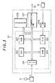
- Fig. 2 is a diagram showing the control unit 20 shown in Fig. 1; reference numbers identical with those in Fig. 1 designate similar parts or elements here.
- reference number 201 designates an A/D converter for converting a pressure signal Pd, which is inputted from the pressure sensor 16, and a slant-plate angular position signal ⁇ , which is inputted from the slant-plate angular position sensor 17, into digital signals;
- 202 a central processing unit (CPU);
- 203 various programs, such as a control program for providing instructions for the central processing unit to perform a control process, a fault analysis program, and a read only memory (ROM) in which constants needed for controlling is stored;
- 204 a random access memory (RAM) for temporarily storing the result of a computation process and interim values during the computing;
- 205 an output interface (I/O); 206, an amplifier for outputting to the slant-plate angular position control unit 19 a drive signal to drive the slant plate of the hydraulic pump 14;
- 207 communication means for controlling communications between the individual control units interconnected by the common communication line 30, the communication means including a memory for storing various communications data; 208, an
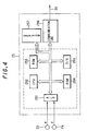
- Fig. 3 is a diagram showing the control unit 22 shown in Fig. 1; reference numbers identical with those in Fig. 1 designate similar parts or elements here.
- reference number 221 designates an A/D converter for converting a control signal X, which is inputted from the boom-control lever 21, into a digital signal; 222, a central processing unit (CPU); 223, various programs, such as a control program for providing instructions for the central processing unit to perform a control process, a fault analysis program, and a read only memory (ROM) in which constants needed for control is stored; 224, a random access memory (RAM) for temporarily storing the result of a computation process and interim values during the computing; 225, a D/A converter for converting a digital signal into an analog signal; 226, an amplifier for outputting to the control valve 15 a signal from the D/A converter 225; 227, communication means for controlling communications between the individual control units interconnected by the common communication line 30, the communication means including a memory for storing various communications data; 228, an EEPROM as a nonvolatile memory in which a history of fault information is stored.
- a control program for providing instructions for the central processing unit to perform a control
- Fig. 4 is a diagram showing the posture computing unit 25 shown in Fig. 1; reference numbers identical with those in Fig. 1 designate similar parts or elements here.
- reference number 251 designates an A/D converter for converting an angle signal ⁇ , which is inputted from the arm angle sensor 23, and an angle signal ⁇ , which is inputted from the boom angle sensor 24, into digital signals; 252, a central processing unit (CPU); 253, various programs, such as a control program for providing instructions for the central processing unit to perform a control process, a fault analysis program, and a read only memory (ROM) in which constants needed for controlling is stored; 254, a random access memory (RAM) for temporarily storing the result of a computation process and interim values during the computing; 255, a D/A converter for converting a digital signal into an analog signal: 256, communication means for controlling communications between the individual control units interconnected by the common communication line 30, the communication means including a memory for storing various communications data; 257, an EEPROM as a nonvolatile memory in which a history of fault information is stored.
- CPU central processing unit
- various programs such as a control program for providing instructions for the central processing unit to perform a control process,
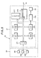
- Fig. 5 is a diagram showing the display unit 26, the display processing unit 27, the display change-over section, and the display section 29 according to the embodiment; reference numbers identical with those in Fig. 1 designate similar parts or elements here.
- reference numbers 281, 282, 283 designate a plurality of display change-over switches for the operator to use when intending to change the contents of display.
- 271 designates an interface for inputting signals from the display change-over switches 281-283; 272, a central processing unit (CPU); 273, various programs, such as a control program for providing instructions for the central processing unit to perform a control process, a fault analysis program, and a read only memory (ROM) in which constants needed for control is stored; 274, a random access memory (RAM) for temporarily storing the result of a computation process and interim values during the computing; 275, an output interface (I/O); 276, an image display control unit for sending data to the display section 29 upon receipt of an command for display on the display section 29; 277, an EEPROM as a nonvolatile memory in which a history of fault information is stored; 278, communication means for controlling communications between the individual control units interconnected by the common communication line 30, the communication means including a memory for storing various communications data.
- CPU central processing unit
- various programs such as a control program for providing instructions for the central processing unit to perform a control process, a fault analysis program, and a read only memory (
- the A/D converter or the interface In the various units 20, 22, 25, 27 shown in Figs. 2 through 5, the A/D converter or the interface, the central processing unit (CPU), the read only memory (ROM), the random access memory (RAM), and the output interface (I/O) or the D/A converter, all encircled by a dotted line, are in the form of a single-chip microcomputer.
- Fig. 6 is a flowchart illustrating the procedure in which an amount of discharge of the hydraulic pump 14 is controlled by the control unit 20 of Fig. 20.
- step 60 constants needed for control are read from the ROM 203 or the EEPROM 208.
- step 61 a pressure signal Pd detected from the pressure sensor 16, a slant-plate angle signal ⁇ detected from the slant-plate angular position sensor 17 and an operating liquid temperature detection signal t of the reservoir 13 are read through the A/D converter 201.
- step 62 a fault diagnosis is performed based on the read numerical data; if the numeral data is over a preset upper limit value or under a preset lower limit value, it is judged that a fault has occurred. The fault diagnosis will be described later in detail.
- step 63 a target turn angle ⁇ r of the hydraulic pump 14 is computed, and in step 64, a control signal is outputted to the slant-plate angular position control unit 19 such that the target turn angle ⁇ r coincides with the slant-plate angular position signal ⁇ to adjust the turn angle of the hydraulic pump 14, thereby controlling the amount of discharge of the hydraulic pump 14.
- Fig. 7 is a flowchart illustrating the procedure in which data sent from the other units 22, 25, 27 via the common communication line 30 are processed by the control unit 20.
- the communication means 207 marks out with a flag indicating the normal completion of data receipt and sends a receipt-completion interruption signal to the control unit 20.
- the received data is stored in the memory inside the communication means 207.
- the control unit 20 Upon receipt of the receipt-completion interruption signal, the control unit 20 automatically start a receipt-completion interruption processing program shown in Fig. 7.
- step 70 the data stored in the communication means 207 is transferred to the RAM 204. Then in step 71, the flag is cleared away because of the data receipt completion.
- the control unit 20 performs a necessary computing process in accordance with the control program stored in the ROM 203 using data stored in the RAM 204.
- Fig. 8 is a flowchart illustrating the procedure in which data is sent to the other units 22, 25, 27 via the common communication line 30 in the control unit 20.
- step 80 data to be sent is transferred from the RAM 204 of FIG. 2 to the memory inside the communication means 207. Then in step 81, a transmission request flag requesting to send data is marked out.
- the communication means 207 converts the data, for which the transmission request flag has been marked out, into a time-series serial data and then sends to the common communication line 30.
- Fig. 9 is a flowchart illustrating the procedure in which constants needed for control computation are read from the ROM 223 or the EEPROM 228.
- a control signal X from the boom-control lever 21 is read through the A/D converter 221.
- a fault diagnosis is performed using the control signal X; if the control signal X is over a preset upper limit value or under a preset lower limit value, it is judged that a fault has occurred. The fault diagnosis will be described later in detail.
- step 93 an extent of control of the control valve 15 corresponding to the control signal X is computed.
- step 94 the extent of control of the control valve 15 is outputted through the D/A converter 225 and the amplifier 226.
- Fig. 10 is a flowchart illustrating the procedure in which the posture computing unit 25 computes a posture of the front mechanism 5.
- step 100 for computing a posture of the front mechanism 5
- size data such as of the boom 6 and the arm 7 which constitute the front mechanism 5 is read from the ROM 253 or the EEPROM 257.
- step 101 an angle signal ⁇ from the boom angle sensor 23 and an angle signal ⁇ from the arm angle sensor 24 are read through the A/D converter 251.
- step 102 a fault diagnosis is performed using the angle signals; if the angle signal ⁇ and the angle signal ⁇ are over a preset upper limit value or under a preset lower limit value, it is judged that a fault has occurred. The fault diagnosis will be described later in detail.
- step 103 a posture of the front mechanism 5 is computed using the size data and the angle signals ⁇ , ⁇ of the individual parts of the front mechanism 5 and the computed posture is stored in the RAM 254.
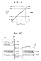
- Fig. 11 is a graph showing one example of input/output characteristic in the A/D converter 201 shown in Fig. 2.
- the slant-plate angular position sensor 17 detects a turn angle defining the angular position of the slant plate of the hydraulic pump 14 and outputs a voltage signal of 0V to 5V commensurate with the detected angle. Assuming that this electrical signal is converted from an analog signal to an 8-bit digital signal of a0 to a4 by the A/D converter 201 and that the slant-plate angular position sensor 17 can detect the range of -20° to 160° as 0V to 5V, a digital value for -20° and a digital value for 160° are correlated with a0 and a4, respectively, and the correlation between these two values is set as a linear proportional relation.
- a digital value when a possible range of the slant-plate turn angle of the hydraulic pump 14 is set to 45° at maximum and that the slant-plate angular position sensor 17 is mounted so as to output a signal representing 0° at the minimum angular position a value to be obtained through the A/D converter 201 will be approximately within the range of a1 to a2; this is, a value smaller than a1 or a value larger than a2 will not be inputted structurally.
- Fig. 12 is a diagram showing the relationship between fault flags and fault history flags stored in a RAM 204 and an EEROM 208 in Fig. 2.
- reference number 2041 designates a ⁇ fault flag to be set when a fault in connection with a slant-plate turn angle ⁇ is judged; 2042, a Pd fault flag to be set when a fault in connection with a pressure signal Pd is judged; 2043, a ⁇ fault history flag in connection with a slant-plate turn angle ⁇ ; 2044, a Pd fault history flag in connection with a pressure signal Pd; 2081, a ⁇ fault history flag in connection with a slant-plate turn angle ⁇ ; 2082, a Pd fault history flag in connection with a pressure signal Pd.
- ⁇ fault history flag 2081 "1" is written if a value of the slant-plate angular position signal ⁇ had have come into the fault analysis region.
- the ⁇ fault history flag 2043 and the Pd fault history flag 2044 in the RAM204 are a copy of the ⁇ fault history flag 2081 and the Pd fault history flag 2082 , respectively, in the EEPROM 208; copying takes place when the control unit 20 is started. The fault information will be retained in the EEPROM 208 all times even when the fault information in the RAM 204 is erased.
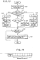
- Fig. 13 is a flowchart illustrating the procedure in which a fault diagnosing program is executed based on the slant-plate turn angle ⁇ in the control unit 20.
- the range in which a fault is diagnosed is set to be over a3 and under a1 in Fig. 11.
- step 120 the slant-plate angular position signal ⁇ is read via the A/D converter 201. Then in step 121, as the result of checking a value of the slant-plate angular position signal ⁇ , a judgment is made in the following cases: if the slant-plate angular position signal ⁇ is smaller than a1 as the result of checking a value of the read slant-plate angular position signal ⁇ , namely, the slant-plate turn angle is under -2°, and if the slant-plate angular position signal ⁇ is larger than a3. And the same judgment is made also in the three additional cases individually as follows.
- step 121 if the slant-plate angular position signal ⁇ is judged as smaller than a1, procedure advances to step 122 where though smaller than a1, the slant-plate angular position signal ⁇ is represented by a1. Then in step 123, the ⁇ fault flag 2041 of the RAM 204 is set to "1". Then in step 124, the fault information is sent to the display processing unit 27 in the procedure shown in Fig. 8.
- step 121 if the slant-plate angular position signal ⁇ is judged as larger than a3, the procedure advances to step 125 where because its read value is larger than a3, the slant-plate angular position signal ⁇ is represented by a3.
- step 126 the ⁇ fault flag 2041 is set to "1". And the fault information is sent to the display processing unit 27 in the procedure shown in Fig. 8.
- step 128 it is checked whether the ⁇ fault flag 2041 of the RAM 204 is set to "0". And if the ⁇ fault flag is judged as being not "0", the procedure advances to step 129 where the fault flag 2041 is set to "0".
- step 130 it is checked whether the ⁇ fault flag 2041 of the RAM 204 is set to "1" and also whether the ⁇ faul history flag 2043 is set to "0". If these conditions are positively established, because it proves that a new fault has occurred, the procedure advances to step 131 where the ⁇ fault flag 2043 of the RAM 204 is set to "1" and "1" is transferred to a fault history flag 2081 in the EEPROM 208.
- Fig. 14 is a diagram schematically showing a message as a minimum unit of data to be sent/received between the units 20, 22, 25 and the display processing unit 27.
- This message is composed of at most eight of byte (8-bit) data and an ID number peculiar to the message; receiving is restricted by the ID number. For example, if a message of ID number A is sent from the display processing unit 27 respectively for the control unit 20, the control unit 22 and the posture computing unit 25, receiving restriction is such that the control unit 20 and the control unit 22 receives the message while the posture computing unit 25 does not receive the same message. Then in the control unit 20 and the control unit 22, the received message is stored in the respective memories of the communication means 207 and the communication means 227.
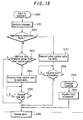
- Fig. 15 is a flowchart illustrating the procedure in which the display processing unit 27 performs a display change-over control in response to a display change-over request of the operator.
- the display change-over request of the operator is made by operating any of the display change-over switches 281-283 in the display change-over section shown in Fig. 5.
- step 150 a control signal from any display change-over switch 281-283 is stored into the display processing unit 27 via the interface 271, and in step 151, such inputted control information is analyzed. Then in step 152, it is discriminated whether the control information is a maintenance-inspection mode or not. If it is not a maintenance-inspection mode, in step 153, it is discriminated whether the contents of the display request is different from the then-current display contents; if data held by another unit is needed, the procedure advances to step 154. In step 154, a request is made to send data needed for the control unit 20, the control unit 22 and the posture computing unit 25.
- Fig. 16 is a diagram schematically showing the contents of a message A to be sent from the display processing unit 27 to the units 20, 22, 25.
- the message A is sent from the display processing unit 27 to the control unit 20, the control unit 22 and the posture computing unit 25 when the actuating liquid temperature t is to be displayed on the display section 29. Since the message A is marked up with a flag requesting the actuating liquid temperature t, the control unit 20 of the hydraulic pump 14 sends, upon receipt of this message, a message B containing the actuating liquid temperature t to the display processing unit 27.
- Fig. 17 is a diagram schematically showing the contents of the message B at that time.
- the display processing unit 27 sends to the control unit 20, the control unit 22 and the posture computing unit 25 the message A with its contents substituted by a message A'.
- Fig. 18 is a diagram schematically showing the contents of the message A' at that time.
- the message A' is a message to be sent from the display processing unit 27 to the control unit 20, the control unit 22 and the posture computing unit 25 if the front depth d is to be displayed on the display section 29. Since the message A' is marked up with a flag requesting the front depth d, the posture computing unit 25 sends, upon receipt of this message, a message C containing the front depth d to the display processing unit 27.
- Fig. 19 is a diagram schematically showing the contents of the message C at that time.
- step 155 of the flowchart shown in Fig. 15 if the display processing unit 27 receives a new message, e.g., the message C, the display processing unit 27 displays the front depth d of the front mechanism 5 on the display section 29 in step 156.
- a new message e.g., the message C
- step 159 fault information from the other units is successively received in step 160, and the received fault information is displayed on the display section 29 in step 156.
- step 150 for maintenance-inspection on a construction machine, when the operator or other workperson makes a request to change the display, such request is accomplished by operating any of the display change-over switches 281-283 in the display change-over section 28.
- step 151 the control information stored in the display processing unit 27 is analyzed.
- step 152 it is discriminated whether the control information is maintenance-inspection mode; in this case, since it is maintenance-inspection mode, the display processing unit 27 requests the control units 20, 22 and the posture computing unit 25 to send data needed for maintenance-inspection in step 157.
- Fig. 20 is a diagram schematically showing the contents of a message A'' sent from the display processing unit 27 to the other units. The message contents are equivalent to the message shown in Fig. 16 or Fig. 18 with the flag portion of fault diagnosis mode K alternatively assuming "1" (ON).
- Fig. 21 is a diagram schematically showing the contents of a message D to be sent by the control unit 20 when the control unit 20 detects a possible fault of the actuating liquid temperature sensor upon receipt of the message in which the flag of fault diagnosis mode K assumes "1".
- a flag to display a fault of pressure Pd of the pump-discharge pressure sensor 16 a flag to display a fault of slant-turn angle ⁇ of the slant-plate angular position sensor 17 and a flag to display a fault of actuating liquid temperature t of the actuating liquid temperature sensor 18, the flag of the actuating liquid temperature t assumes "1".
- Fig. 22 is a diagram schematically showing the contents of a message E to be sent by the control unit 22 when the control unit detects a possible fault of the boom-control lever 21 upon receipt of the message in which the flag of fault diagnosis mode K assume "1".
- the flag to display a fault of control x of the boom-control lever 21 In Fig. 22, the flag to display a fault of control x of the boom-control lever 21.
- Fig. 23 is a diagram schematically showing the contents of a message E to be sent by the posture computing unit 25 when the posture computing unit detects a possible fault with respect to the detection signal ⁇ from the boom angle sensor 23 and the detection signal ⁇ from the arm angle sensor 24 upon receipt of the message in which the flag of fault diagnosis mode K assumes "1".
- the flag to display a fault of the detection signal ⁇ and detection signal ⁇ assumes "1".
- fault information is displayed in preference to and in place of the then-currently displayed information.
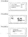
- Fig. 24 is a composite diagram showing various examples of display selectively displayed on the display section 29 of Fig. 1;
- Fig. 24(a) shows an example displaying a then-current operating state of the construction machine, such as current r.p.m of engine, actuating liquid temperature and operating time,
- Fig. 24(b) shows another example displaying an inclined image of the construction machine and an angle of inclination of the construction machine with respect to the ground level, and
- Fig. 24(c) shows still another example displaying fault information of the construction machine.
- this embodiment it is possible to display on a single display section a plurality of different kinds of information, such as information needed for operation, fault information and fault history information, selectively one at a time. Since fault information is displayed in preference to any other information, the operator can become aware of the fault information without delay so that any possible misoperation of the construction machine due to a fault of a sensor or an actuator can be avoided.
- the display unit displays on a single display section various kinds of information selectively one at a time, it is possible not only to reduce the cost of a display unit but also to enlarge the space inside a cab.
- control units which control the respective operations of various construction machine parts based on information collected from sensor means provided in the individual construction machine parts, are connected to a display unit, which displays a state of the individual construction machine part, by a common communication line, it is possible to display on a single display section input signals, fault information, interim results of control computation, fault history information, etc. of sensors and actuators mounted in the individual machine parts selectively one at a time in response to an command from the display unit.
- a single display unit is provided inside a cab, it is possible to secure an enlarged space inside the cab, thus making the cab more comfortable for the operator to work inside.
Landscapes
- Engineering & Computer Science (AREA)
- Mining & Mineral Resources (AREA)
- Civil Engineering (AREA)
- General Engineering & Computer Science (AREA)
- Structural Engineering (AREA)
- Physics & Mathematics (AREA)
- Fluid Mechanics (AREA)
- Component Parts Of Construction Machinery (AREA)
- Operation Control Of Excavators (AREA)
- Control Of Indicators Other Than Cathode Ray Tubes (AREA)
- Testing And Monitoring For Control Systems (AREA)
Claims (3)
- Anzeigesteuereinrichtung für eine Baumaschine, die umfasst:Erfassungsmittel (16, 17, 18; 23, 24; 21), die in jedem von verschiedenen Teilen der Baumaschine vorgesehen sind;mehrere Steuereinheiten (20, 22, 25) zum Steuern des jeweiligen Betriebs der einzelnen Teile der Baumaschine anhand von Informationen, die von den Erfassungsmitteln gesammelt werden; undeine Anzeigeeinheit (26), die mit den Steuereinheiten (20, 22, 25) über eine gemeinsame Kommunikationsleitung (30) verbunden ist, um die jeweiligen Betriebszustände der einzelnen Teile der Baumaschine anzuzeigen;wobei die Anzeigeeinheit (26) Eingabemittel (28) zum Eingeben von Befehlen zum Ändern von Anzeigeinformationen, die die Betriebszustände der einzelnen Teile der Baumaschine repräsentieren, und Anzeigemittel (29) zum Lesen der den eingegebenen Befehlen entsprechenden Anzeigeinformationen von den einzelnen Steuereinheiten (20, 22, 25) und zum Anzeigen der gelesenen Anzeigeinformationen,wobei die Anzeigemittel einen einzigen Anzeigeabschnitt (29) zum Anzeigen verschiedener Arten der zu ändernden Anzeigeinformationen besitzen, wobei die Anzeigesteuereinrichtung dadurch gekennzeichnet ist, dass:jede Steuereinheit (20, 22, 25) Fehler-Diagnosemittel zum Diagnostizieren eines möglichen Fehlers der Erfassungsmittel, die der entsprechenden Steuereinheit zugeordnet sind, und eines möglichen Fehlers der zu steuernden einzelnen Teile besitzt, unddie Steuereinheit (26) in Reaktion auf die Fehlererfassung durch die Fehler-Diagnosemittel jeder Steuereinheit die Fehler-Informationen vorrangig gegenüber den Nichtfehler-Anzeigeinformationen anzeigt.
- Anzeigesteuereinrichtung für eine Baumaschine nach Anspruch 1, bei der die Fehler-Diagnosemittel jeder Steuereinheit einen möglichen Fehler wenigstens der Erfassungsmittel (16-18; 23, 24; 21) und eines Stellgliedes der Baumaschine diagnostizieren.
- Anzeigesteuereinrichtung für eine Baumaschine nach Anspruch 1 oder 2, bei der die Befehle Befehle zum Senden der Fehler-Informationen enthalten.
Applications Claiming Priority (3)
| Application Number | Priority Date | Filing Date | Title |
|---|---|---|---|
| JP10108095A JPH11303151A (ja) | 1998-04-17 | 1998-04-17 | 建設機械の表示制御装置 |
| JP10809598 | 1998-04-17 | ||
| PCT/JP1999/002059 WO1999054558A1 (en) | 1998-04-17 | 1999-04-19 | Display controller of construction machine |
Publications (4)
| Publication Number | Publication Date |
|---|---|
| EP0990740A1 EP0990740A1 (de) | 2000-04-05 |
| EP0990740A4 EP0990740A4 (de) | 2002-06-05 |
| EP0990740B1 true EP0990740B1 (de) | 2007-06-27 |
| EP0990740B8 EP0990740B8 (de) | 2007-09-05 |
Family
ID=14475757
Family Applications (1)
| Application Number | Title | Priority Date | Filing Date |
|---|---|---|---|
| EP99913703A Expired - Lifetime EP0990740B8 (de) | 1998-04-17 | 1999-04-19 | Anzeigesteuergerät für eine baumaschine |
Country Status (6)
| Country | Link |
|---|---|
| EP (1) | EP0990740B8 (de) |
| JP (1) | JPH11303151A (de) |
| KR (1) | KR100371275B1 (de) |
| CN (1) | CN1086762C (de) |
| DE (1) | DE69936369T2 (de) |
| WO (1) | WO1999054558A1 (de) |
Cited By (1)
| Publication number | Priority date | Publication date | Assignee | Title |
|---|---|---|---|---|
| US9322147B2 (en) | 2011-11-15 | 2016-04-26 | Komatsu Ltd. | Information display device of construction machine, information display method of construction machine, and information display computer program of construction machine |
Families Citing this family (13)
| Publication number | Priority date | Publication date | Assignee | Title |
|---|---|---|---|---|
| KR100489503B1 (ko) * | 1999-12-22 | 2005-05-16 | 현대중공업 주식회사 | 조작 스위치에 의한 휠로더 작업장치 조종 시스템 |
| KR100450545B1 (ko) * | 2001-10-31 | 2004-09-30 | 대우종합기계 주식회사 | 굴삭기용 사용자 인터페이스 장치 |
| JP4506286B2 (ja) | 2003-08-19 | 2010-07-21 | 株式会社小松製作所 | 建設機械 |
| JP3902168B2 (ja) * | 2003-09-04 | 2007-04-04 | 日立建機株式会社 | 建設機械の診断情報表示システム |
| JP2005113397A (ja) * | 2003-10-03 | 2005-04-28 | Hitachi Constr Mach Co Ltd | 建設機械の表示装置 |
| KR100621982B1 (ko) * | 2004-04-13 | 2006-09-14 | 볼보 컨스트럭션 이키프먼트 홀딩 스웨덴 에이비 | 중장비의 기능스위치 패턴설정장치 |
| JP4749035B2 (ja) * | 2005-05-24 | 2011-08-17 | 株式会社小松製作所 | モニタ装置 |
| KR100652876B1 (ko) * | 2005-09-26 | 2006-12-01 | 볼보 컨스트럭션 이키프먼트 홀딩 스웨덴 에이비 | 건설기계의 무선전장 시스템 및 이를 이용한 건설기계메인터넌스 시스템 |
| EP2808455B1 (de) * | 2012-01-27 | 2018-05-30 | Doosan Infracore Co., Ltd. | Vorrichtung zur erhöhung der betriebsstabilität einer baumaschine |
| KR101928576B1 (ko) * | 2012-01-30 | 2018-12-12 | 두산인프라코어 주식회사 | 건설기계의 연비 정보 제공 시스템 |
| CN107620340B (zh) * | 2012-07-19 | 2020-12-11 | 住友建机株式会社 | 挖土机 |
| JP5938341B2 (ja) * | 2012-12-18 | 2016-06-22 | 日立建機株式会社 | 電動式建設機械 |
| KR20210007447A (ko) | 2019-07-11 | 2021-01-20 | 두산인프라코어 주식회사 | 건설 중장비의 인터페이스 장치 및 이를 이용한 제어방법 |
Family Cites Families (9)
| Publication number | Priority date | Publication date | Assignee | Title |
|---|---|---|---|---|
| JPH04136327A (ja) * | 1990-09-27 | 1992-05-11 | Komatsu Ltd | 腕式多関節型建設機械 |
| JP2912495B2 (ja) * | 1992-04-13 | 1999-06-28 | 新キャタピラー三菱株式会社 | 多機能ディスプレイモニタ装置とその操作方法 |
| JPH07119183A (ja) * | 1993-10-21 | 1995-05-09 | Hitachi Constr Mach Co Ltd | 油圧作業機のモニタ装置 |
| JPH09151491A (ja) * | 1995-11-24 | 1997-06-10 | Tokai Rika Co Ltd | 表示装置 |
| JPH09221972A (ja) * | 1996-02-19 | 1997-08-26 | Makita Corp | 縦型ブラインドの駆動装置 |
| JP3539815B2 (ja) * | 1996-02-19 | 2004-07-07 | 日立建機株式会社 | 建設機械の電子制御装置の故障診断表示装置 |
| JP3310852B2 (ja) * | 1996-03-18 | 2002-08-05 | 日立建機株式会社 | 建設機械の故障診断装置 |
| US5854988A (en) * | 1996-06-05 | 1998-12-29 | Topcon Laser Systems, Inc. | Method for controlling an excavator |
| DE19737858A1 (de) * | 1997-07-10 | 1999-01-14 | Siemens Ag | Schaufelradgerät |
-
1998
- 1998-04-17 JP JP10108095A patent/JPH11303151A/ja active Pending
-
1999
- 1999-04-19 KR KR10-1999-7011853A patent/KR100371275B1/ko not_active Expired - Fee Related
- 1999-04-19 WO PCT/JP1999/002059 patent/WO1999054558A1/ja not_active Ceased
- 1999-04-19 CN CN99800563A patent/CN1086762C/zh not_active Expired - Fee Related
- 1999-04-19 DE DE69936369T patent/DE69936369T2/de not_active Expired - Fee Related
- 1999-04-19 EP EP99913703A patent/EP0990740B8/de not_active Expired - Lifetime
Cited By (1)
| Publication number | Priority date | Publication date | Assignee | Title |
|---|---|---|---|---|
| US9322147B2 (en) | 2011-11-15 | 2016-04-26 | Komatsu Ltd. | Information display device of construction machine, information display method of construction machine, and information display computer program of construction machine |
Also Published As
| Publication number | Publication date |
|---|---|
| DE69936369T2 (de) | 2008-03-13 |
| WO1999054558A1 (en) | 1999-10-28 |
| CN1263577A (zh) | 2000-08-16 |
| JPH11303151A (ja) | 1999-11-02 |
| EP0990740A4 (de) | 2002-06-05 |
| KR20010013833A (ko) | 2001-02-26 |
| CN1086762C (zh) | 2002-06-26 |
| EP0990740A1 (de) | 2000-04-05 |
| DE69936369D1 (de) | 2007-08-09 |
| EP0990740B8 (de) | 2007-09-05 |
| KR100371275B1 (ko) | 2003-02-05 |
Similar Documents
| Publication | Publication Date | Title |
|---|---|---|
| EP0990740B1 (de) | Anzeigesteuergerät für eine baumaschine | |
| EP1206731B1 (de) | Diagnose- und steuerungseinheit für ein arbeitsfahrzeug | |
| US5555171A (en) | Data collection system for driving machine | |
| EP0781888B1 (de) | Hydraulischer Kreislauf für einen hydraulischen Schaufelbagger | |
| EP2131045B1 (de) | Sicherheitsvorrichtung für hydraulische arbeitsmaschine | |
| EP3744908B1 (de) | Steuerungsvorrichtung für arbeitsmaschinen | |
| JP4489258B2 (ja) | 建設機械の電子制御システム | |
| JP4896775B2 (ja) | 油圧作業機械の安全装置 | |
| AU9460798A (en) | Control apparatus and control method for a construction machine | |
| JPH01192921A (ja) | 建設機械の作業機位置制御装置 | |
| KR20050016186A (ko) | 고장 진단 장치 | |
| JP4897152B2 (ja) | 建設機械の故障診断方法および建設機械の故障診断システム | |
| JPH0719207A (ja) | 油圧機械の駆動制御装置 | |
| JP4405159B2 (ja) | 建設機械の情報管理装置 | |
| US5810046A (en) | Device and method for selecting control mode in power construction vehicle | |
| JPH04503500A (ja) | オートクレーン、大型ショベルカー等の装置の監視方法およびこの方法を実施するためのシステム | |
| JP3748587B2 (ja) | 建設機械の電子制御装置 | |
| JPH11324025A (ja) | 建設機械における分散型制御装置 | |
| JP2000328610A (ja) | 作業機 | |
| JP3635173B2 (ja) | 作業機械の保守システム | |
| JP3539815B2 (ja) | 建設機械の電子制御装置の故障診断表示装置 | |
| JPH10206304A (ja) | 材料試験機の遠隔指令システム | |
| JPH11324024A (ja) | 建設機械における分散型制御装置 | |
| JPH04136327A (ja) | 腕式多関節型建設機械 | |
| JP4042234B2 (ja) | Faネットワーク及びロボットコントローラ |
Legal Events
| Date | Code | Title | Description |
|---|---|---|---|
| PUAI | Public reference made under article 153(3) epc to a published international application that has entered the european phase |
Free format text: ORIGINAL CODE: 0009012 |
|
| 17P | Request for examination filed |
Effective date: 19991220 |
|
| AK | Designated contracting states |
Kind code of ref document: A1 Designated state(s): DE FR GB IT SE |
|
| A4 | Supplementary search report drawn up and despatched |
Effective date: 20020418 |
|
| AK | Designated contracting states |
Kind code of ref document: A4 Designated state(s): DE FR GB IT SE |
|
| GRAP | Despatch of communication of intention to grant a patent |
Free format text: ORIGINAL CODE: EPIDOSNIGR1 |
|
| GRAS | Grant fee paid |
Free format text: ORIGINAL CODE: EPIDOSNIGR3 |
|
| GRAA | (expected) grant |
Free format text: ORIGINAL CODE: 0009210 |
|
| AK | Designated contracting states |
Kind code of ref document: B1 Designated state(s): DE FR GB IT SE |
|
| REG | Reference to a national code |
Ref country code: GB Ref legal event code: FG4D |
|
| RAP2 | Party data changed (patent owner data changed or rights of a patent transferred) |
Owner name: HITACHI CONSTRUCTION MACHINERY CO., LTD. |
|
| REF | Corresponds to: |
Ref document number: 69936369 Country of ref document: DE Date of ref document: 20070809 Kind code of ref document: P |
|
| PG25 | Lapsed in a contracting state [announced via postgrant information from national office to epo] |
Ref country code: SE Free format text: LAPSE BECAUSE OF FAILURE TO SUBMIT A TRANSLATION OF THE DESCRIPTION OR TO PAY THE FEE WITHIN THE PRESCRIBED TIME-LIMIT Effective date: 20070927 |
|
| EN | Fr: translation not filed | ||
| PG25 | Lapsed in a contracting state [announced via postgrant information from national office to epo] |
Ref country code: IT Free format text: LAPSE BECAUSE OF FAILURE TO SUBMIT A TRANSLATION OF THE DESCRIPTION OR TO PAY THE FEE WITHIN THE PRESCRIBED TIME-LIMIT Effective date: 20070627 |
|
| PLBE | No opposition filed within time limit |
Free format text: ORIGINAL CODE: 0009261 |
|
| STAA | Information on the status of an ep patent application or granted ep patent |
Free format text: STATUS: NO OPPOSITION FILED WITHIN TIME LIMIT |
|
| 26N | No opposition filed |
Effective date: 20080328 |
|
| PG25 | Lapsed in a contracting state [announced via postgrant information from national office to epo] |
Ref country code: FR Free format text: LAPSE BECAUSE OF FAILURE TO SUBMIT A TRANSLATION OF THE DESCRIPTION OR TO PAY THE FEE WITHIN THE PRESCRIBED TIME-LIMIT Effective date: 20080222 |
|
| GBPC | Gb: european patent ceased through non-payment of renewal fee |
Effective date: 20080419 |
|
| PG25 | Lapsed in a contracting state [announced via postgrant information from national office to epo] |
Ref country code: DE Free format text: LAPSE BECAUSE OF NON-PAYMENT OF DUE FEES Effective date: 20081101 |
|
| PG25 | Lapsed in a contracting state [announced via postgrant information from national office to epo] |
Ref country code: GB Free format text: LAPSE BECAUSE OF NON-PAYMENT OF DUE FEES Effective date: 20080419 |