EP0990740B1 - Display controller of construction machine - Google Patents
Display controller of construction machine Download PDFInfo
- Publication number
- EP0990740B1 EP0990740B1 EP99913703A EP99913703A EP0990740B1 EP 0990740 B1 EP0990740 B1 EP 0990740B1 EP 99913703 A EP99913703 A EP 99913703A EP 99913703 A EP99913703 A EP 99913703A EP 0990740 B1 EP0990740 B1 EP 0990740B1
- Authority
- EP
- European Patent Office
- Prior art keywords
- display
- fault
- construction machine
- control unit
- control
- Prior art date
- Legal status (The legal status is an assumption and is not a legal conclusion. Google has not performed a legal analysis and makes no representation as to the accuracy of the status listed.)
- Expired - Lifetime
Links
Images


Classifications
-
- E—FIXED CONSTRUCTIONS
- E02—HYDRAULIC ENGINEERING; FOUNDATIONS; SOIL SHIFTING
- E02F—DREDGING; SOIL-SHIFTING
- E02F9/00—Component parts of dredgers or soil-shifting machines, not restricted to one of the kinds covered by groups E02F3/00 - E02F7/00
- E02F9/26—Indicating devices
-
- E—FIXED CONSTRUCTIONS
- E02—HYDRAULIC ENGINEERING; FOUNDATIONS; SOIL SHIFTING
- E02F—DREDGING; SOIL-SHIFTING
- E02F9/00—Component parts of dredgers or soil-shifting machines, not restricted to one of the kinds covered by groups E02F3/00 - E02F7/00
- E02F9/20—Drives; Control devices
-
- E—FIXED CONSTRUCTIONS
- E02—HYDRAULIC ENGINEERING; FOUNDATIONS; SOIL SHIFTING
- E02F—DREDGING; SOIL-SHIFTING
- E02F9/00—Component parts of dredgers or soil-shifting machines, not restricted to one of the kinds covered by groups E02F3/00 - E02F7/00
- E02F9/20—Drives; Control devices
- E02F9/22—Hydraulic or pneumatic drives
- E02F9/2221—Control of flow rate; Load sensing arrangements
- E02F9/2232—Control of flow rate; Load sensing arrangements using one or more variable displacement pumps
- E02F9/2235—Control of flow rate; Load sensing arrangements using one or more variable displacement pumps including an electronic controller
-
- E—FIXED CONSTRUCTIONS
- E02—HYDRAULIC ENGINEERING; FOUNDATIONS; SOIL SHIFTING
- E02F—DREDGING; SOIL-SHIFTING
- E02F9/00—Component parts of dredgers or soil-shifting machines, not restricted to one of the kinds covered by groups E02F3/00 - E02F7/00
- E02F9/20—Drives; Control devices
- E02F9/22—Hydraulic or pneumatic drives
- E02F9/2278—Hydraulic circuits
- E02F9/2285—Pilot-operated systems
-
- E—FIXED CONSTRUCTIONS
- E02—HYDRAULIC ENGINEERING; FOUNDATIONS; SOIL SHIFTING
- E02F—DREDGING; SOIL-SHIFTING
- E02F9/00—Component parts of dredgers or soil-shifting machines, not restricted to one of the kinds covered by groups E02F3/00 - E02F7/00
- E02F9/20—Drives; Control devices
- E02F9/22—Hydraulic or pneumatic drives
- E02F9/2278—Hydraulic circuits
- E02F9/2296—Systems with a variable displacement pump
Definitions
- This invention relates to a display controller for a construction machine, and more particularly to a display controller, for a construction machine such as a hydraulic excavator, which can display detection information and fault information from a plurality of control units to control the construction machine.
- a controller mounted in a construction machine such as a hydraulic excavator, generally comprises a first control unit for giving a control command to the construction machine, a second control unit for giving a control computation command necessary to control the individual construction machine parts based on the control command from the first control unit, a third control unit for outputting the computation control commands of the second control unit to actuators to drive the individual construction machine parts, and a display unit for displaying various kinds of information involved in the construction machine. Between these control units and the display unit, a multiplicity of electric signal lines are arranged to transfer related signals to one another.
- an ordinary construction machine requires a display unit for displaying various kinds of information, such as a remaining amount of fuel needed during normal operation, r.p.m. of engine, and actuating liquid temperature, and another display unit for displaying fault information of the machine and its history information.
- an additional display unit is required for displaying a posture of a front mechanism mounted on a front portion of a construction machine body and is equipped with a control switch to start and stop automatic controlling.
- the cab is to be provided with a display unit serving also as plural operating sections
- display unit is mounted usually at a position front right of the operator in the cab.
- DE 297 15 552 U discloses a display controller for a construction machine according to the preamble of claim 1.
- JP 09 256 422 A discloses a failure diagnostic device comprising control means and separate portable failure diagnostic means.
- a display controller for a construction machine having the additional features as disclosed in the characterising part of claim 1,
- the fault-diagnosing means of each control unit diagnoses a possible fault of at least the detecting means and an actuator of the construction machine.
- the commands include commands to send the fault information.
- reference number 1 designates a construction machine, such as a hydraulic excavator; the construction machine 1 generally comprises a travel base 2, a swivel superstructure 3 mounted on the travel base 2, a cab 4 carried by a front portion of the swivel superstructure 3, a front mechanism 5 supported on the front portion of the swivel superstructure 3, a boom 6 vertically angularly movably mounted on the swivel superstructure 3, an arm 7 pivotally mounted on a distal end of the boom 6, a bucket 8 pivotally mounted on a distal end of the arm 7, a hydraulic cylinder 9 for vertically angularly moving the boom 6, a hydraulic cylinder 10 for pivotally moving the arm 7, a hydraulic cylinder 11 for pivotally moving the bucket 8, and a link mechanism 12 connecting between the hydraulic cylinder 11 and the bucket 8.
- the construction machine 1 generally comprises a travel base 2, a swivel superstructure 3 mounted on the travel base 2, a cab 4 carried by a front portion of the swivel superstructure
- reference number 13 designates a reservoir; 14, a hydraulic pump; 15, a control valve for controlling an amount of flow of pressurized liquid to be supplied from the hydraulic pump 14 to the boom-moving hydraulic cylinder 9; 16, a pressure sensor for detecting a discharge pressure of the hydraulic pump 14; 17, a slant-plate angular position sensor for detecting an angular position of a slant plate of the hydraulic pump 14; 18, an actuating liquid temperature sensor for detecting a temperature of actuating liquid of the reservoir; and 19, a slant-plate angular position control unit for controlling an angular position of the slant plate of the hydraulic pump 14.
- 20 designates a control unit for the hydraulic pump 14; the control unit 20 adjusts the angular position of the slant plate of the hydraulic pump 14 via the slant-plate angular position control unit 19 based on a pressure signal Pd from the pressure sensor 16 and a slant-plate angle signal ⁇ from the slant-plate angular position sensor 17 to control a volume of forced-out liquid, i.e. an amount of flow of discharged liquid, of the hydraulic pump 14.
- 21 designates a boom-control lever
- 22 designates a boom control unit operatively connected to the boom-control lever 21; the boom control unit 22 controls the control valve 15 based on an control signal X from the boom-control lever 21 to adjust the extent of opening of the valve, thereby driving the boom.
- Fig. 1 only the control system composed of the control valve 15 for controlling the boom-driving hydraulic cylinder 9, the boom-control lever 21 and the boom control unit 22 is illustrated, while the illustration of the control system for driving the arm-driving hydraulic cylinder 10, the bucket-driving hydraulic cylinder 11, a swivel-superstructure-driving hydraulic motor and a travel-base-driving hydraulic motor is omitted here to avoid making the description complex.
- a boom angle sensor for detecting an angle of angular movement of the boom 6
- an arm angle sensor for detecting an angle of pivotal movement of the arm 7
- a posture computing unit for computing a posture of the front mechanism 5 based on a detection signal ⁇ and a detection signal ⁇ respectively from the boom angle sensor 23 and the arm angle sensor 24.
- 26 designates a display unit; 27, a display processing unit; 28, a display change-over section; 29, a display section.
- the display processing unit 27, the posture computing unit 25, the boom control unit 22, and the control unit 20 of the hydraulic pump 14 are interconnected by a common communication line 30 for bi-directional communications.
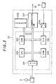
- Fig. 2 is a diagram showing the control unit 20 shown in Fig. 1; reference numbers identical with those in Fig. 1 designate similar parts or elements here.
- reference number 201 designates an A/D converter for converting a pressure signal Pd, which is inputted from the pressure sensor 16, and a slant-plate angular position signal ⁇ , which is inputted from the slant-plate angular position sensor 17, into digital signals;
- 202 a central processing unit (CPU);
- 203 various programs, such as a control program for providing instructions for the central processing unit to perform a control process, a fault analysis program, and a read only memory (ROM) in which constants needed for controlling is stored;
- 204 a random access memory (RAM) for temporarily storing the result of a computation process and interim values during the computing;
- 205 an output interface (I/O); 206, an amplifier for outputting to the slant-plate angular position control unit 19 a drive signal to drive the slant plate of the hydraulic pump 14;
- 207 communication means for controlling communications between the individual control units interconnected by the common communication line 30, the communication means including a memory for storing various communications data; 208, an
- Fig. 3 is a diagram showing the control unit 22 shown in Fig. 1; reference numbers identical with those in Fig. 1 designate similar parts or elements here.
- reference number 221 designates an A/D converter for converting a control signal X, which is inputted from the boom-control lever 21, into a digital signal; 222, a central processing unit (CPU); 223, various programs, such as a control program for providing instructions for the central processing unit to perform a control process, a fault analysis program, and a read only memory (ROM) in which constants needed for control is stored; 224, a random access memory (RAM) for temporarily storing the result of a computation process and interim values during the computing; 225, a D/A converter for converting a digital signal into an analog signal; 226, an amplifier for outputting to the control valve 15 a signal from the D/A converter 225; 227, communication means for controlling communications between the individual control units interconnected by the common communication line 30, the communication means including a memory for storing various communications data; 228, an EEPROM as a nonvolatile memory in which a history of fault information is stored.
- a control program for providing instructions for the central processing unit to perform a control
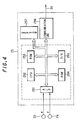
- Fig. 4 is a diagram showing the posture computing unit 25 shown in Fig. 1; reference numbers identical with those in Fig. 1 designate similar parts or elements here.
- reference number 251 designates an A/D converter for converting an angle signal ⁇ , which is inputted from the arm angle sensor 23, and an angle signal ⁇ , which is inputted from the boom angle sensor 24, into digital signals; 252, a central processing unit (CPU); 253, various programs, such as a control program for providing instructions for the central processing unit to perform a control process, a fault analysis program, and a read only memory (ROM) in which constants needed for controlling is stored; 254, a random access memory (RAM) for temporarily storing the result of a computation process and interim values during the computing; 255, a D/A converter for converting a digital signal into an analog signal: 256, communication means for controlling communications between the individual control units interconnected by the common communication line 30, the communication means including a memory for storing various communications data; 257, an EEPROM as a nonvolatile memory in which a history of fault information is stored.
- CPU central processing unit
- various programs such as a control program for providing instructions for the central processing unit to perform a control process,
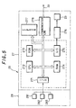
- Fig. 5 is a diagram showing the display unit 26, the display processing unit 27, the display change-over section, and the display section 29 according to the embodiment; reference numbers identical with those in Fig. 1 designate similar parts or elements here.
- reference numbers 281, 282, 283 designate a plurality of display change-over switches for the operator to use when intending to change the contents of display.
- 271 designates an interface for inputting signals from the display change-over switches 281-283; 272, a central processing unit (CPU); 273, various programs, such as a control program for providing instructions for the central processing unit to perform a control process, a fault analysis program, and a read only memory (ROM) in which constants needed for control is stored; 274, a random access memory (RAM) for temporarily storing the result of a computation process and interim values during the computing; 275, an output interface (I/O); 276, an image display control unit for sending data to the display section 29 upon receipt of an command for display on the display section 29; 277, an EEPROM as a nonvolatile memory in which a history of fault information is stored; 278, communication means for controlling communications between the individual control units interconnected by the common communication line 30, the communication means including a memory for storing various communications data.
- CPU central processing unit
- various programs such as a control program for providing instructions for the central processing unit to perform a control process, a fault analysis program, and a read only memory (
- the A/D converter or the interface In the various units 20, 22, 25, 27 shown in Figs. 2 through 5, the A/D converter or the interface, the central processing unit (CPU), the read only memory (ROM), the random access memory (RAM), and the output interface (I/O) or the D/A converter, all encircled by a dotted line, are in the form of a single-chip microcomputer.
- Fig. 6 is a flowchart illustrating the procedure in which an amount of discharge of the hydraulic pump 14 is controlled by the control unit 20 of Fig. 20.
- step 60 constants needed for control are read from the ROM 203 or the EEPROM 208.
- step 61 a pressure signal Pd detected from the pressure sensor 16, a slant-plate angle signal ⁇ detected from the slant-plate angular position sensor 17 and an operating liquid temperature detection signal t of the reservoir 13 are read through the A/D converter 201.
- step 62 a fault diagnosis is performed based on the read numerical data; if the numeral data is over a preset upper limit value or under a preset lower limit value, it is judged that a fault has occurred. The fault diagnosis will be described later in detail.
- step 63 a target turn angle ⁇ r of the hydraulic pump 14 is computed, and in step 64, a control signal is outputted to the slant-plate angular position control unit 19 such that the target turn angle ⁇ r coincides with the slant-plate angular position signal ⁇ to adjust the turn angle of the hydraulic pump 14, thereby controlling the amount of discharge of the hydraulic pump 14.
- Fig. 7 is a flowchart illustrating the procedure in which data sent from the other units 22, 25, 27 via the common communication line 30 are processed by the control unit 20.
- the communication means 207 marks out with a flag indicating the normal completion of data receipt and sends a receipt-completion interruption signal to the control unit 20.
- the received data is stored in the memory inside the communication means 207.
- the control unit 20 Upon receipt of the receipt-completion interruption signal, the control unit 20 automatically start a receipt-completion interruption processing program shown in Fig. 7.
- step 70 the data stored in the communication means 207 is transferred to the RAM 204. Then in step 71, the flag is cleared away because of the data receipt completion.
- the control unit 20 performs a necessary computing process in accordance with the control program stored in the ROM 203 using data stored in the RAM 204.
- Fig. 8 is a flowchart illustrating the procedure in which data is sent to the other units 22, 25, 27 via the common communication line 30 in the control unit 20.
- step 80 data to be sent is transferred from the RAM 204 of FIG. 2 to the memory inside the communication means 207. Then in step 81, a transmission request flag requesting to send data is marked out.
- the communication means 207 converts the data, for which the transmission request flag has been marked out, into a time-series serial data and then sends to the common communication line 30.
- Fig. 9 is a flowchart illustrating the procedure in which constants needed for control computation are read from the ROM 223 or the EEPROM 228.
- a control signal X from the boom-control lever 21 is read through the A/D converter 221.
- a fault diagnosis is performed using the control signal X; if the control signal X is over a preset upper limit value or under a preset lower limit value, it is judged that a fault has occurred. The fault diagnosis will be described later in detail.
- step 93 an extent of control of the control valve 15 corresponding to the control signal X is computed.
- step 94 the extent of control of the control valve 15 is outputted through the D/A converter 225 and the amplifier 226.
- Fig. 10 is a flowchart illustrating the procedure in which the posture computing unit 25 computes a posture of the front mechanism 5.
- step 100 for computing a posture of the front mechanism 5
- size data such as of the boom 6 and the arm 7 which constitute the front mechanism 5 is read from the ROM 253 or the EEPROM 257.
- step 101 an angle signal ⁇ from the boom angle sensor 23 and an angle signal ⁇ from the arm angle sensor 24 are read through the A/D converter 251.
- step 102 a fault diagnosis is performed using the angle signals; if the angle signal ⁇ and the angle signal ⁇ are over a preset upper limit value or under a preset lower limit value, it is judged that a fault has occurred. The fault diagnosis will be described later in detail.
- step 103 a posture of the front mechanism 5 is computed using the size data and the angle signals ⁇ , ⁇ of the individual parts of the front mechanism 5 and the computed posture is stored in the RAM 254.
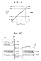
- Fig. 11 is a graph showing one example of input/output characteristic in the A/D converter 201 shown in Fig. 2.
- the slant-plate angular position sensor 17 detects a turn angle defining the angular position of the slant plate of the hydraulic pump 14 and outputs a voltage signal of 0V to 5V commensurate with the detected angle. Assuming that this electrical signal is converted from an analog signal to an 8-bit digital signal of a0 to a4 by the A/D converter 201 and that the slant-plate angular position sensor 17 can detect the range of -20° to 160° as 0V to 5V, a digital value for -20° and a digital value for 160° are correlated with a0 and a4, respectively, and the correlation between these two values is set as a linear proportional relation.
- a digital value when a possible range of the slant-plate turn angle of the hydraulic pump 14 is set to 45° at maximum and that the slant-plate angular position sensor 17 is mounted so as to output a signal representing 0° at the minimum angular position a value to be obtained through the A/D converter 201 will be approximately within the range of a1 to a2; this is, a value smaller than a1 or a value larger than a2 will not be inputted structurally.
- Fig. 12 is a diagram showing the relationship between fault flags and fault history flags stored in a RAM 204 and an EEROM 208 in Fig. 2.
- reference number 2041 designates a ⁇ fault flag to be set when a fault in connection with a slant-plate turn angle ⁇ is judged; 2042, a Pd fault flag to be set when a fault in connection with a pressure signal Pd is judged; 2043, a ⁇ fault history flag in connection with a slant-plate turn angle ⁇ ; 2044, a Pd fault history flag in connection with a pressure signal Pd; 2081, a ⁇ fault history flag in connection with a slant-plate turn angle ⁇ ; 2082, a Pd fault history flag in connection with a pressure signal Pd.
- ⁇ fault history flag 2081 "1" is written if a value of the slant-plate angular position signal ⁇ had have come into the fault analysis region.
- the ⁇ fault history flag 2043 and the Pd fault history flag 2044 in the RAM204 are a copy of the ⁇ fault history flag 2081 and the Pd fault history flag 2082 , respectively, in the EEPROM 208; copying takes place when the control unit 20 is started. The fault information will be retained in the EEPROM 208 all times even when the fault information in the RAM 204 is erased.
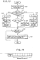
- Fig. 13 is a flowchart illustrating the procedure in which a fault diagnosing program is executed based on the slant-plate turn angle ⁇ in the control unit 20.
- the range in which a fault is diagnosed is set to be over a3 and under a1 in Fig. 11.
- step 120 the slant-plate angular position signal ⁇ is read via the A/D converter 201. Then in step 121, as the result of checking a value of the slant-plate angular position signal ⁇ , a judgment is made in the following cases: if the slant-plate angular position signal ⁇ is smaller than a1 as the result of checking a value of the read slant-plate angular position signal ⁇ , namely, the slant-plate turn angle is under -2°, and if the slant-plate angular position signal ⁇ is larger than a3. And the same judgment is made also in the three additional cases individually as follows.
- step 121 if the slant-plate angular position signal ⁇ is judged as smaller than a1, procedure advances to step 122 where though smaller than a1, the slant-plate angular position signal ⁇ is represented by a1. Then in step 123, the ⁇ fault flag 2041 of the RAM 204 is set to "1". Then in step 124, the fault information is sent to the display processing unit 27 in the procedure shown in Fig. 8.
- step 121 if the slant-plate angular position signal ⁇ is judged as larger than a3, the procedure advances to step 125 where because its read value is larger than a3, the slant-plate angular position signal ⁇ is represented by a3.
- step 126 the ⁇ fault flag 2041 is set to "1". And the fault information is sent to the display processing unit 27 in the procedure shown in Fig. 8.
- step 128 it is checked whether the ⁇ fault flag 2041 of the RAM 204 is set to "0". And if the ⁇ fault flag is judged as being not "0", the procedure advances to step 129 where the fault flag 2041 is set to "0".
- step 130 it is checked whether the ⁇ fault flag 2041 of the RAM 204 is set to "1" and also whether the ⁇ faul history flag 2043 is set to "0". If these conditions are positively established, because it proves that a new fault has occurred, the procedure advances to step 131 where the ⁇ fault flag 2043 of the RAM 204 is set to "1" and "1" is transferred to a fault history flag 2081 in the EEPROM 208.
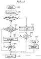
- Fig. 14 is a diagram schematically showing a message as a minimum unit of data to be sent/received between the units 20, 22, 25 and the display processing unit 27.
- This message is composed of at most eight of byte (8-bit) data and an ID number peculiar to the message; receiving is restricted by the ID number. For example, if a message of ID number A is sent from the display processing unit 27 respectively for the control unit 20, the control unit 22 and the posture computing unit 25, receiving restriction is such that the control unit 20 and the control unit 22 receives the message while the posture computing unit 25 does not receive the same message. Then in the control unit 20 and the control unit 22, the received message is stored in the respective memories of the communication means 207 and the communication means 227.
- Fig. 15 is a flowchart illustrating the procedure in which the display processing unit 27 performs a display change-over control in response to a display change-over request of the operator.
- the display change-over request of the operator is made by operating any of the display change-over switches 281-283 in the display change-over section shown in Fig. 5.
- step 150 a control signal from any display change-over switch 281-283 is stored into the display processing unit 27 via the interface 271, and in step 151, such inputted control information is analyzed. Then in step 152, it is discriminated whether the control information is a maintenance-inspection mode or not. If it is not a maintenance-inspection mode, in step 153, it is discriminated whether the contents of the display request is different from the then-current display contents; if data held by another unit is needed, the procedure advances to step 154. In step 154, a request is made to send data needed for the control unit 20, the control unit 22 and the posture computing unit 25.
- Fig. 16 is a diagram schematically showing the contents of a message A to be sent from the display processing unit 27 to the units 20, 22, 25.
- the message A is sent from the display processing unit 27 to the control unit 20, the control unit 22 and the posture computing unit 25 when the actuating liquid temperature t is to be displayed on the display section 29. Since the message A is marked up with a flag requesting the actuating liquid temperature t, the control unit 20 of the hydraulic pump 14 sends, upon receipt of this message, a message B containing the actuating liquid temperature t to the display processing unit 27.
- Fig. 17 is a diagram schematically showing the contents of the message B at that time.
- the display processing unit 27 sends to the control unit 20, the control unit 22 and the posture computing unit 25 the message A with its contents substituted by a message A'.
- Fig. 18 is a diagram schematically showing the contents of the message A' at that time.
- the message A' is a message to be sent from the display processing unit 27 to the control unit 20, the control unit 22 and the posture computing unit 25 if the front depth d is to be displayed on the display section 29. Since the message A' is marked up with a flag requesting the front depth d, the posture computing unit 25 sends, upon receipt of this message, a message C containing the front depth d to the display processing unit 27.
- Fig. 19 is a diagram schematically showing the contents of the message C at that time.
- step 155 of the flowchart shown in Fig. 15 if the display processing unit 27 receives a new message, e.g., the message C, the display processing unit 27 displays the front depth d of the front mechanism 5 on the display section 29 in step 156.
- a new message e.g., the message C
- step 159 fault information from the other units is successively received in step 160, and the received fault information is displayed on the display section 29 in step 156.
- step 150 for maintenance-inspection on a construction machine, when the operator or other workperson makes a request to change the display, such request is accomplished by operating any of the display change-over switches 281-283 in the display change-over section 28.
- step 151 the control information stored in the display processing unit 27 is analyzed.
- step 152 it is discriminated whether the control information is maintenance-inspection mode; in this case, since it is maintenance-inspection mode, the display processing unit 27 requests the control units 20, 22 and the posture computing unit 25 to send data needed for maintenance-inspection in step 157.
- Fig. 20 is a diagram schematically showing the contents of a message A'' sent from the display processing unit 27 to the other units. The message contents are equivalent to the message shown in Fig. 16 or Fig. 18 with the flag portion of fault diagnosis mode K alternatively assuming "1" (ON).
- Fig. 21 is a diagram schematically showing the contents of a message D to be sent by the control unit 20 when the control unit 20 detects a possible fault of the actuating liquid temperature sensor upon receipt of the message in which the flag of fault diagnosis mode K assumes "1".
- a flag to display a fault of pressure Pd of the pump-discharge pressure sensor 16 a flag to display a fault of slant-turn angle ⁇ of the slant-plate angular position sensor 17 and a flag to display a fault of actuating liquid temperature t of the actuating liquid temperature sensor 18, the flag of the actuating liquid temperature t assumes "1".
- Fig. 22 is a diagram schematically showing the contents of a message E to be sent by the control unit 22 when the control unit detects a possible fault of the boom-control lever 21 upon receipt of the message in which the flag of fault diagnosis mode K assume "1".
- the flag to display a fault of control x of the boom-control lever 21 In Fig. 22, the flag to display a fault of control x of the boom-control lever 21.
- Fig. 23 is a diagram schematically showing the contents of a message E to be sent by the posture computing unit 25 when the posture computing unit detects a possible fault with respect to the detection signal ⁇ from the boom angle sensor 23 and the detection signal ⁇ from the arm angle sensor 24 upon receipt of the message in which the flag of fault diagnosis mode K assumes "1".
- the flag to display a fault of the detection signal ⁇ and detection signal ⁇ assumes "1".
- fault information is displayed in preference to and in place of the then-currently displayed information.
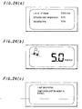
- Fig. 24 is a composite diagram showing various examples of display selectively displayed on the display section 29 of Fig. 1;
- Fig. 24(a) shows an example displaying a then-current operating state of the construction machine, such as current r.p.m of engine, actuating liquid temperature and operating time,
- Fig. 24(b) shows another example displaying an inclined image of the construction machine and an angle of inclination of the construction machine with respect to the ground level, and
- Fig. 24(c) shows still another example displaying fault information of the construction machine.
- this embodiment it is possible to display on a single display section a plurality of different kinds of information, such as information needed for operation, fault information and fault history information, selectively one at a time. Since fault information is displayed in preference to any other information, the operator can become aware of the fault information without delay so that any possible misoperation of the construction machine due to a fault of a sensor or an actuator can be avoided.
- the display unit displays on a single display section various kinds of information selectively one at a time, it is possible not only to reduce the cost of a display unit but also to enlarge the space inside a cab.
- control units which control the respective operations of various construction machine parts based on information collected from sensor means provided in the individual construction machine parts, are connected to a display unit, which displays a state of the individual construction machine part, by a common communication line, it is possible to display on a single display section input signals, fault information, interim results of control computation, fault history information, etc. of sensors and actuators mounted in the individual machine parts selectively one at a time in response to an command from the display unit.
- a single display unit is provided inside a cab, it is possible to secure an enlarged space inside the cab, thus making the cab more comfortable for the operator to work inside.
Abstract
Description
- This invention relates to a display controller for a construction machine, and more particularly to a display controller, for a construction machine such as a hydraulic excavator, which can display detection information and fault information from a plurality of control units to control the construction machine.
- Hitherto, a controller mounted in a construction machine, such as a hydraulic excavator, generally comprises a first control unit for giving a control command to the construction machine, a second control unit for giving a control computation command necessary to control the individual construction machine parts based on the control command from the first control unit, a third control unit for outputting the computation control commands of the second control unit to actuators to drive the individual construction machine parts, and a display unit for displaying various kinds of information involved in the construction machine. Between these control units and the display unit, a multiplicity of electric signal lines are arranged to transfer related signals to one another.
- This arrangement of multiple electric signal lines is accomplished by wiring connection and would therefore make the whole structure complex, resulting in an increased price. In order to solve this problem, a display controller for a construction machine has been proposed, by
Japanese Patent Publication No. HEI 7-113854 - In the meantime, for its better operativeness, an ordinary construction machine requires a display unit for displaying various kinds of information, such as a remaining amount of fuel needed during normal operation, r.p.m. of engine, and actuating liquid temperature, and another display unit for displaying fault information of the machine and its history information. And for a highly sophisticated construction machine in particular, an additional display unit is required for displaying a posture of a front mechanism mounted on a front portion of a construction machine body and is equipped with a control switch to start and stop automatic controlling.
- However, if the above-mentioned plural display units are connected to the above-mentioned plural control units, which are arranged and distributed over the individual construction machine parts, via the common communication line, it would require an increased number of connecting wires, thus resulting in complicated wiring. Further, if all the plural display units are mounted inside the cab of the construction machine, the cab would be narrowed in space so that the operator can work only uncomfortably in the cab.
- Furthermore, assuming that the cab is to be provided with a display unit serving also as plural operating sections, such display unit is mounted usually at a position front right of the operator in the cab. With this arrangement, the operator must keep particular attention to the display unit and operate the operating sections associated with the display unit, in addition to operation of a boom-control lever, which would be large labor to the operator.
- With the foregoing various problems, it is an object of this invention to provide a display controller, for a construction machine, which can secure enough space inside a cab and hence improve the workability of the operator inside the cab.
- It is noted that
DE 297 15 552 U (Siemens A.G .) discloses a display controller for a construction machine according to the preamble ofclaim 1. Further, it is noted thatJP 09 256 422 A (Hitachi Constr. Mach. Co. LTD - In order to accomplish the above object, there is provided a display controller for a construction machine, having the additional features as disclosed in the characterising part of
claim 1, - According to
claim 2 in addition to the features recited inclaim 1, the fault-diagnosing means of each control unit diagnoses a possible fault of at least the detecting means and an actuator of the construction machine. - According to
claim 3 in addition to the features recited inclaim -
- Fig. 1 is a diagram generally showing a display controller, for a construction machine, according to one embodiment of this invention; Fig. 2 is a diagram schematically showing a
control unit 20 shown in Fig. - One embodiment of this invention will now be described using Figs. 1 to 24.
- Fig. 1 is a diagram schematically showing a display controller, for a construction machine, according to this embodiment.
- In Fig. 1,
reference number 1 designates a construction machine, such as a hydraulic excavator; theconstruction machine 1 generally comprises atravel base 2, aswivel superstructure 3 mounted on thetravel base 2, a cab 4 carried by a front portion of theswivel superstructure 3, a front mechanism 5 supported on the front portion of theswivel superstructure 3, aboom 6 vertically angularly movably mounted on theswivel superstructure 3, anarm 7 pivotally mounted on a distal end of theboom 6, abucket 8 pivotally mounted on a distal end of thearm 7, ahydraulic cylinder 9 for vertically angularly moving theboom 6, ahydraulic cylinder 10 for pivotally moving thearm 7, ahydraulic cylinder 11 for pivotally moving thebucket 8, and alink mechanism 12 connecting between thehydraulic cylinder 11 and thebucket 8. - An electrical system and a hydraulic system depicted outside the
construction machine 1 in Fig. 1 are actually arranged in theconstruction machine 1. - In these control systems,
reference number 13 designates a reservoir; 14, a hydraulic pump; 15, a control valve for controlling an amount of flow of pressurized liquid to be supplied from thehydraulic pump 14 to the boom-movinghydraulic cylinder 9; 16, a pressure sensor for detecting a discharge pressure of thehydraulic pump 14; 17, a slant-plate angular position sensor for detecting an angular position of a slant plate of thehydraulic pump 14; 18, an actuating liquid temperature sensor for detecting a temperature of actuating liquid of the reservoir; and 19, a slant-plate angular position control unit for controlling an angular position of the slant plate of thehydraulic pump 14. - Further, 20 designates a control unit for the
hydraulic pump 14; thecontrol unit 20 adjusts the angular position of the slant plate of thehydraulic pump 14 via the slant-plate angularposition control unit 19 based on a pressure signal Pd from thepressure sensor 16 and a slant-plate angle signal θ from the slant-plateangular position sensor 17 to control a volume of forced-out liquid, i.e. an amount of flow of discharged liquid, of thehydraulic pump 14. Furthermore, 21 designates a boom-control lever, and 22 designates a boom control unit operatively connected to the boom-control lever 21; theboom control unit 22 controls thecontrol valve 15 based on an control signal X from the boom-control lever 21 to adjust the extent of opening of the valve, thereby driving the boom. - In Fig. 1, only the control system composed of the
control valve 15 for controlling the boom-drivinghydraulic cylinder 9, the boom-control lever 21 and theboom control unit 22 is illustrated, while the illustration of the control system for driving the arm-drivinghydraulic cylinder 10, the bucket-drivinghydraulic cylinder 11, a swivel-superstructure-driving hydraulic motor and a travel-base-driving hydraulic motor is omitted here to avoid making the description complex. - 23 designates a boom angle sensor for detecting an angle of angular movement of the
boom 6; 24, an arm angle sensor for detecting an angle of pivotal movement of thearm 7; 25, a posture computing unit for computing a posture of the front mechanism 5 based on a detection signal α and a detection signal β respectively from theboom angle sensor 23 and thearm angle sensor 24. - 26 designates a display unit; 27, a display processing unit; 28, a display change-over section; 29, a display section.
- The
display processing unit 27, theposture computing unit 25, theboom control unit 22, and thecontrol unit 20 of thehydraulic pump 14 are interconnected by acommon communication line 30 for bi-directional communications. - Fig. 2 is a diagram showing the
control unit 20 shown in Fig. 1; reference numbers identical with those in Fig. 1 designate similar parts or elements here. - In Fig. 2,
reference number 201 designates an A/D converter for converting a pressure signal Pd, which is inputted from thepressure sensor 16, and a slant-plate angular position signal θ, which is inputted from the slant-plateangular position sensor 17, into digital signals; 202, a central processing unit (CPU); 203, various programs, such as a control program for providing instructions for the central processing unit to perform a control process, a fault analysis program, and a read only memory (ROM) in which constants needed for controlling is stored; 204, a random access memory (RAM) for temporarily storing the result of a computation process and interim values during the computing; 205, an output interface (I/O); 206, an amplifier for outputting to the slant-plate angular position control unit 19 a drive signal to drive the slant plate of thehydraulic pump 14; 207, communication means for controlling communications between the individual control units interconnected by thecommon communication line 30, the communication means including a memory for storing various communications data; 208, an EEPROM (Electrically Erasable Programmable Read Only Memory) as a nonvolatile memory in which a history of fault information is stored even in off-power state. - Fig. 3 is a diagram showing the
control unit 22 shown in Fig. 1; reference numbers identical with those in Fig. 1 designate similar parts or elements here. - In Fig. 3,
reference number 221 designates an A/D converter for converting a control signal X, which is inputted from the boom-control lever 21, into a digital signal; 222, a central processing unit (CPU); 223, various programs, such as a control program for providing instructions for the central processing unit to perform a control process, a fault analysis program, and a read only memory (ROM) in which constants needed for control is stored; 224, a random access memory (RAM) for temporarily storing the result of a computation process and interim values during the computing; 225, a D/A converter for converting a digital signal into an analog signal; 226, an amplifier for outputting to the control valve 15 a signal from the D/A converter 225; 227, communication means for controlling communications between the individual control units interconnected by thecommon communication line 30, the communication means including a memory for storing various communications data; 228, an EEPROM as a nonvolatile memory in which a history of fault information is stored. - Fig. 4 is a diagram showing the
posture computing unit 25 shown in Fig. 1; reference numbers identical with those in Fig. 1 designate similar parts or elements here. - In Fig. 4,
reference number 251 designates an A/D converter for converting an angle signal α, which is inputted from thearm angle sensor 23, and an angle signal β, which is inputted from theboom angle sensor 24, into digital signals; 252, a central processing unit (CPU); 253, various programs, such as a control program for providing instructions for the central processing unit to perform a control process, a fault analysis program, and a read only memory (ROM) in which constants needed for controlling is stored; 254, a random access memory (RAM) for temporarily storing the result of a computation process and interim values during the computing; 255, a D/A converter for converting a digital signal into an analog signal: 256, communication means for controlling communications between the individual control units interconnected by thecommon communication line 30, the communication means including a memory for storing various communications data; 257, an EEPROM as a nonvolatile memory in which a history of fault information is stored. - Fig. 5 is a diagram showing the
display unit 26, thedisplay processing unit 27, the display change-over section, and thedisplay section 29 according to the embodiment; reference numbers identical with those in Fig. 1 designate similar parts or elements here. - In Fig. 5,
reference numbers - 271 designates an interface for inputting signals from the display change-over switches 281-283; 272, a central processing unit (CPU); 273, various programs, such as a control program for providing instructions for the central processing unit to perform a control process, a fault analysis program, and a read only memory (ROM) in which constants needed for control is stored; 274, a random access memory (RAM) for temporarily storing the result of a computation process and interim values during the computing; 275, an output interface (I/O); 276, an image display control unit for sending data to the
display section 29 upon receipt of an command for display on thedisplay section 29; 277, an EEPROM as a nonvolatile memory in which a history of fault information is stored; 278, communication means for controlling communications between the individual control units interconnected by thecommon communication line 30, the communication means including a memory for storing various communications data. - In the
various units - The mode of operation of the
control unit 20 of Fig. 2 will now be described using Figs. 6 to 8. - Fig. 6 is a flowchart illustrating the procedure in which an amount of discharge of the
hydraulic pump 14 is controlled by thecontrol unit 20 of Fig. 20. - First of all, in
step 60, constants needed for control are read from theROM 203 or the EEPROM 208. Then instep 61, a pressure signal Pd detected from thepressure sensor 16, a slant-plate angle signal θ detected from the slant-plateangular position sensor 17 and an operating liquid temperature detection signal t of thereservoir 13 are read through the A/D converter 201. Then instep 62, a fault diagnosis is performed based on the read numerical data; if the numeral data is over a preset upper limit value or under a preset lower limit value, it is judged that a fault has occurred. The fault diagnosis will be described later in detail. Then instep 63, a target turn angle θr of thehydraulic pump 14 is computed, and instep 64, a control signal is outputted to the slant-plate angularposition control unit 19 such that the target turn angle θr coincides with the slant-plate angular position signal θ to adjust the turn angle of thehydraulic pump 14, thereby controlling the amount of discharge of thehydraulic pump 14. - Fig. 7 is a flowchart illustrating the procedure in which data sent from the
other units common communication line 30 are processed by thecontrol unit 20. First of all, after it has normally completed the receiving of data from theother units control unit 20. At that time, the received data is stored in the memory inside the communication means 207. Upon receipt of the receipt-completion interruption signal, thecontrol unit 20 automatically start a receipt-completion interruption processing program shown in Fig. 7. - As the interruption process starts, in step 70, the data stored in the communication means 207 is transferred to the
RAM 204. Then in step 71, the flag is cleared away because of the data receipt completion. - The
control unit 20 performs a necessary computing process in accordance with the control program stored in theROM 203 using data stored in theRAM 204. - In the foregoing description, the data receiving process is explained only when the
control unit 20 receives data from the other units; actually the same data receiving process takes place in connection with any other unit. - Fig. 8 is a flowchart illustrating the procedure in which data is sent to the
other units common communication line 30 in thecontrol unit 20. - In step 80, data to be sent is transferred from the
RAM 204 of FIG. 2 to the memory inside the communication means 207. Then in step 81, a transmission request flag requesting to send data is marked out. The communication means 207 converts the data, for which the transmission request flag has been marked out, into a time-series serial data and then sends to thecommon communication line 30. - In the foregoing description, the data transmission process is explained only when the
control unit 20 sends data to the other units; the same data transmission process takes place also in connection with any other unit. - Fig. 9 is a flowchart illustrating the procedure in which constants needed for control computation are read from the
ROM 223 or theEEPROM 228. Then instep 91, a control signal X from the boom-control lever 21 is read through the A/D converter 221. Then in step 92, a fault diagnosis is performed using the control signal X; if the control signal X is over a preset upper limit value or under a preset lower limit value, it is judged that a fault has occurred. The fault diagnosis will be described later in detail. Then in step 93, an extent of control of thecontrol valve 15 corresponding to the control signal X is computed. Then in step 94, the extent of control of thecontrol valve 15 is outputted through the D/A converter 225 and theamplifier 226. - Fig. 10 is a flowchart illustrating the procedure in which the
posture computing unit 25 computes a posture of the front mechanism 5. - First of all, in step 100, for computing a posture of the front mechanism 5, size data such as of the
boom 6 and thearm 7 which constitute the front mechanism 5 is read from theROM 253 or theEEPROM 257. Then in step 101, an angle signal α from theboom angle sensor 23 and an angle signal β from thearm angle sensor 24 are read through the A/D converter 251. Then in step 102, a fault diagnosis is performed using the angle signals; if the angle signal α and the angle signal β are over a preset upper limit value or under a preset lower limit value, it is judged that a fault has occurred. The fault diagnosis will be described later in detail. Then in step 103, a posture of the front mechanism 5 is computed using the size data and the angle signals α, β of the individual parts of the front mechanism 5 and the computed posture is stored in theRAM 254. - The fault analysis in the
control unit 20 based on the slant-plate angular position signal θ detected by the slant-plateangular position sensor 17 will now be described using Figs. 11 through 13. - Fig. 11 is a graph showing one example of input/output characteristic in the A/
D converter 201 shown in Fig. 2. - In Fig. 11, the slant-plate
angular position sensor 17 detects a turn angle defining the angular position of the slant plate of thehydraulic pump 14 and outputs a voltage signal of 0V to 5V commensurate with the detected angle. Assuming that this electrical signal is converted from an analog signal to an 8-bit digital signal of a0 to a4 by the A/D converter 201 and that the slant-plateangular position sensor 17 can detect the range of -20° to 160° as 0V to 5V, a digital value for -20° and a digital value for 160° are correlated with a0 and a4, respectively, and the correlation between these two values is set as a linear proportional relation. - Now assuming that a digital value when a possible range of the slant-plate turn angle of the
hydraulic pump 14 is set to 45° at maximum and that the slant-plateangular position sensor 17 is mounted so as to output a signal representing 0° at the minimum angular position, a value to be obtained through the A/D converter 201 will be approximately within the range of a1 to a2; this is, a value smaller than a1 or a value larger than a2 will not be inputted structurally. Using this principle, it is possible to perform a fault analysis of the slant-plateangular position sensor 17. - Fig. 12 is a diagram showing the relationship between fault flags and fault history flags stored in a
RAM 204 and anEEROM 208 in Fig. 2. - In Fig. 12,
reference number 2041 designates a θ fault flag to be set when a fault in connection with a slant-plate turn angle θ is judged; 2042, a Pd fault flag to be set when a fault in connection with a pressure signal Pd is judged; 2043, a θ fault history flag in connection with a slant-plate turn angle θ; 2044, a Pd fault history flag in connection with a pressure signal Pd; 2081, a θ fault history flag in connection with a slant-plate turn angle θ; 2082, a Pd fault history flag in connection with a pressure signal Pd. - In the θ
fault history flag 2081, "1" is written if a value of the slant-plate angular position signal θ had have come into the fault analysis region. The θfault history flag 2043 and the Pdfault history flag 2044 in the RAM204 are a copy of the θfault history flag 2081 and the Pdfault history flag 2082 , respectively, in theEEPROM 208; copying takes place when thecontrol unit 20 is started. The fault information will be retained in theEEPROM 208 all times even when the fault information in theRAM 204 is erased. - Fig. 13 is a flowchart illustrating the procedure in which a fault diagnosing program is executed based on the slant-plate turn angle θ in the
control unit 20. In view of allowance, the range in which a fault is diagnosed is set to be over a3 and under a1 in Fig. 11. - In Fig. 13, in
step 120, the slant-plate angular position signal θ is read via the A/D converter 201. Then in step 121, as the result of checking a value of the slant-plate angular position signal θ, a judgment is made in the following cases: if the slant-plate angular position signal θ is smaller than a1 as the result of checking a value of the read slant-plate angular position signal θ, namely, the slant-plate turn angle is under -2°, and if the slant-plate angular position signal θ is larger than a3. And the same judgment is made also in the three additional cases individually as follows. If the slant-plate angular position signal θ is smaller than a1 or larger than a3, a possible concern is exemplified by a fault of the slant-plateangular position sensor 17, and a break-out or short-circuit of electric wiring between thecontrol unit 20 and the slant-plateangular position sensor 17. In step 121, if the slant-plate angular position signal θ is judged as smaller than a1, procedure advances to step 122 where though smaller than a1, the slant-plate angular position signal θ is represented by a1. Then in step 123, theθ fault flag 2041 of theRAM 204 is set to "1". Then in step 124, the fault information is sent to thedisplay processing unit 27 in the procedure shown in Fig. 8. - And in step 121, if the slant-plate angular position signal θ is judged as larger than a3, the procedure advances to step 125 where because its read value is larger than a3, the slant-plate angular position signal θ is represented by a3.
- Subsequently, in step 126, the
θ fault flag 2041 is set to "1". And the fault information is sent to thedisplay processing unit 27 in the procedure shown in Fig. 8. - If the slant-plate angular position signal θ is outside the fault diagnosis region, the procedure advances to step 128 where it is checked whether the
θ fault flag 2041 of theRAM 204 is set to "0". And if the θ fault flag is judged as being not "0", the procedure advances to step 129 where thefault flag 2041 is set to "0". - Then in step 130, it is checked whether the
θ fault flag 2041 of theRAM 204 is set to "1" and also whether the θfaul history flag 2043 is set to "0". If these conditions are positively established, because it proves that a new fault has occurred, the procedure advances to step 131 where theθ fault flag 2043 of theRAM 204 is set to "1" and "1" is transferred to afault history flag 2081 in theEEPROM 208. - By the foregoing procedure, it is possible to detect a possible fault of the slant-plate
angular position sensor 17 and to store a history of the detected fault in theROM 204 and theEEPROM 208. - The procedure of this fault analysis is illustrated only for the slant-plate turn angle θ in the
control unit 20, but the illustration of the fault analysis procedure for the pressure signal Pd in thecontrol unit 20, thecontrol unit 22, and theposture computing unit 25 is omitted here because the fault analysis procedure is similar to the illustrated one. - The procedure in which the display of data on the
display section 29 is changed one to another between various kinds of display data in thedisplay processing unit 27 of Fig. 1 will now be described using Figs. 14 to 23. - Fig. 14 is a diagram schematically showing a message as a minimum unit of data to be sent/received between the
units display processing unit 27. - This message is composed of at most eight of byte (8-bit) data and an ID number peculiar to the message; receiving is restricted by the ID number. For example, if a message of ID number A is sent from the
display processing unit 27 respectively for thecontrol unit 20, thecontrol unit 22 and theposture computing unit 25, receiving restriction is such that thecontrol unit 20 and thecontrol unit 22 receives the message while theposture computing unit 25 does not receive the same message. Then in thecontrol unit 20 and thecontrol unit 22, the received message is stored in the respective memories of the communication means 207 and the communication means 227. - According to this embodiment, by previously setting for each of the
various units - Fig. 15 is a flowchart illustrating the procedure in which the
display processing unit 27 performs a display change-over control in response to a display change-over request of the operator. - The display change-over request of the operator is made by operating any of the display change-over switches 281-283 in the display change-over section shown in Fig. 5.
- First of all, in step 150, a control signal from any display change-over switch 281-283 is stored into the
display processing unit 27 via theinterface 271, and in step 151, such inputted control information is analyzed. Then in step 152, it is discriminated whether the control information is a maintenance-inspection mode or not. If it is not a maintenance-inspection mode, in step 153, it is discriminated whether the contents of the display request is different from the then-current display contents; if data held by another unit is needed, the procedure advances to step 154. Instep 154, a request is made to send data needed for thecontrol unit 20, thecontrol unit 22 and theposture computing unit 25. - Now assuming that a request is made to display a front depth d while an actuating liquid temperature t is on display, a message requesting to stop sending the message is sent to the
control unit 20, while another message requesting to send the message relating to the depth d of the front mechanism 5 is sent to theposture computing unit 25. - Fig. 16 is a diagram schematically showing the contents of a message A to be sent from the
display processing unit 27 to theunits display processing unit 27 to thecontrol unit 20, thecontrol unit 22 and theposture computing unit 25 when the actuating liquid temperature t is to be displayed on thedisplay section 29. Since the message A is marked up with a flag requesting the actuating liquid temperature t, thecontrol unit 20 of thehydraulic pump 14 sends, upon receipt of this message, a message B containing the actuating liquid temperature t to thedisplay processing unit 27. Fig. 17 is a diagram schematically showing the contents of the message B at that time. - Now assuming that a request is made from the
display processing unit 27 to display the front depth d of the front mechanism 5, thedisplay processing unit 27 sends to thecontrol unit 20, thecontrol unit 22 and theposture computing unit 25 the message A with its contents substituted by a message A'. - Fig. 18 is a diagram schematically showing the contents of the message A' at that time. The message A' is a message to be sent from the
display processing unit 27 to thecontrol unit 20, thecontrol unit 22 and theposture computing unit 25 if the front depth d is to be displayed on thedisplay section 29. Since the message A' is marked up with a flag requesting the front depth d, theposture computing unit 25 sends, upon receipt of this message, a message C containing the front depth d to thedisplay processing unit 27. Fig. 19 is a diagram schematically showing the contents of the message C at that time. - Turning back to step 155 of the flowchart shown in Fig. 15, if the
display processing unit 27 receives a new message, e.g., the message C, thedisplay processing unit 27 displays the front depth d of the front mechanism 5 on thedisplay section 29 in step 156. - As a result of receiving interruption in
step 159, fault information from the other units is successively received instep 160, and the received fault information is displayed on thedisplay section 29 in step 156. - The display process during maintenance-inspection will now be described using again the flowchart shown in Fig. 15.
- In step 150, for maintenance-inspection on a construction machine, when the operator or other workperson makes a request to change the display, such request is accomplished by operating any of the display change-over switches 281-283 in the display change-over
section 28. In step 151, the control information stored in thedisplay processing unit 27 is analyzed. In step 152, it is discriminated whether the control information is maintenance-inspection mode; in this case, since it is maintenance-inspection mode, thedisplay processing unit 27 requests thecontrol units posture computing unit 25 to send data needed for maintenance-inspection in step 157. Fig. 20 is a diagram schematically showing the contents of a message A'' sent from thedisplay processing unit 27 to the other units. The message contents are equivalent to the message shown in Fig. 16 or Fig. 18 with the flag portion of fault diagnosis mode K alternatively assuming "1" (ON). - Fig. 21 is a diagram schematically showing the contents of a message D to be sent by the
control unit 20 when thecontrol unit 20 detects a possible fault of the actuating liquid temperature sensor upon receipt of the message in which the flag of fault diagnosis mode K assumes "1". In Fig. 21, among a flag to display a fault of pressure Pd of the pump-discharge pressure sensor 16, a flag to display a fault of slant-turn angle θ of the slant-plateangular position sensor 17 and a flag to display a fault of actuating liquid temperature t of the actuatingliquid temperature sensor 18, the flag of the actuating liquid temperature t assumes "1". - Fig. 22 is a diagram schematically showing the contents of a message E to be sent by the
control unit 22 when the control unit detects a possible fault of the boom-control lever 21 upon receipt of the message in which the flag of fault diagnosis mode K assume "1". In Fig. 22, the flag to display a fault of control x of the boom-control lever 21. - Fig. 23 is a diagram schematically showing the contents of a message E to be sent by the
posture computing unit 25 when the posture computing unit detects a possible fault with respect to the detection signal α from theboom angle sensor 23 and the detection signal β from thearm angle sensor 24 upon receipt of the message in which the flag of fault diagnosis mode K assumes "1". In Fig. 23, the flag to display a fault of the detection signal α and detection signal β assumes "1". - When the
display processing unit 27 receives a message containing fault information like the above-mentioned messages D, E, F, fault information is displayed in preference to and in place of the then-currently displayed information. - Fig. 24 is a composite diagram showing various examples of display selectively displayed on the
display section 29 of Fig. 1; Fig. 24(a) shows an example displaying a then-current operating state of the construction machine, such as current r.p.m of engine, actuating liquid temperature and operating time, Fig. 24(b) shows another example displaying an inclined image of the construction machine and an angle of inclination of the construction machine with respect to the ground level, and Fig. 24(c) shows still another example displaying fault information of the construction machine. - As described above, according to this embodiment, it is possible to display on a single display section a plurality of different kinds of information, such as information needed for operation, fault information and fault history information, selectively one at a time. Since fault information is displayed in preference to any other information, the operator can become aware of the fault information without delay so that any possible misoperation of the construction machine due to a fault of a sensor or an actuator can be avoided.
- Further, since the display unit displays on a single display section various kinds of information selectively one at a time, it is possible not only to reduce the cost of a display unit but also to enlarge the space inside a cab.
- According to this invention, since a plurality of control units, which control the respective operations of various construction machine parts based on information collected from sensor means provided in the individual construction machine parts, are connected to a display unit, which displays a state of the individual construction machine part, by a common communication line, it is possible to display on a single display section input signals, fault information, interim results of control computation, fault history information, etc. of sensors and actuators mounted in the individual machine parts selectively one at a time in response to an command from the display unit. As a result, since various kinds of information involved in the construction machine can be obtained, it is possible to improve the working efficiency of the operator. Further, since only a single display unit is provided inside a cab, it is possible to secure an enlarged space inside the cab, thus making the cab more comfortable for the operator to work inside.
Claims (3)
- A display controller for a construction machine, comprising:detecting means (16, 17, 18; 23, 24; 21) provided in each of various parts of the construction machine;a plurality of control units (20, 22, 25) for controlling the operations of the individual parts of the construction machine based on information collected from said detecting means; anda display unit (26), connected to said control units (20, 22, 25) with a common communication line (30), for displaying the respective operation states of the individual parts of the construction machine;said display unit (26) including inputting means (28) for inputting commands to change display information representing the operation states of the individual parts of the construction machine, and displaying means (29) for reading from the individual control units (20, 22, 25) the display information corresponding to the inputted commands and displaying the read display information,wherein said displaying means has a single display section (29) for displaying various kinds of the display information to be changed, said display controller characterized in that:each said control unit (20, 22, 25) has fault-diagnosing means for diagnosing a possible fault of said detecting means associated with the corresponding control unit and a possible fault of the individual part to be controlled, andsaid display unit (26) is responsive to the fault detection by said fault-diagnosing means of each said control unit to display said fault information in precedence to the non-fault display information.
- A display controller for a construction machine according to claim 1, wherein said fault-diagnosing means of each said control unit diagnoses a possible fault of at least said detecting means (16-18; 23, 24; 21) and an actuator of the construction machine.
- A display controller for a construction machine according to claim 1 or 2, wherein said commands include commands to send said fault information.
Applications Claiming Priority (3)
| Application Number | Priority Date | Filing Date | Title |
|---|---|---|---|
| JP10809598 | 1998-04-17 | ||
| JP10108095A JPH11303151A (en) | 1998-04-17 | 1998-04-17 | Display control device of construction machine |
| PCT/JP1999/002059 WO1999054558A1 (en) | 1998-04-17 | 1999-04-19 | Display controller of construction machine |
Publications (4)
| Publication Number | Publication Date |
|---|---|
| EP0990740A1 EP0990740A1 (en) | 2000-04-05 |
| EP0990740A4 EP0990740A4 (en) | 2002-06-05 |
| EP0990740B1 true EP0990740B1 (en) | 2007-06-27 |
| EP0990740B8 EP0990740B8 (en) | 2007-09-05 |
Family
ID=14475757
Family Applications (1)
| Application Number | Title | Priority Date | Filing Date |
|---|---|---|---|
| EP99913703A Expired - Lifetime EP0990740B8 (en) | 1998-04-17 | 1999-04-19 | Display controller of construction machine |
Country Status (6)
| Country | Link |
|---|---|
| EP (1) | EP0990740B8 (en) |
| JP (1) | JPH11303151A (en) |
| KR (1) | KR100371275B1 (en) |
| CN (1) | CN1086762C (en) |
| DE (1) | DE69936369T2 (en) |
| WO (1) | WO1999054558A1 (en) |
Cited By (1)
| Publication number | Priority date | Publication date | Assignee | Title |
|---|---|---|---|---|
| US9322147B2 (en) | 2011-11-15 | 2016-04-26 | Komatsu Ltd. | Information display device of construction machine, information display method of construction machine, and information display computer program of construction machine |
Families Citing this family (13)
| Publication number | Priority date | Publication date | Assignee | Title |
|---|---|---|---|---|
| KR100489503B1 (en) * | 1999-12-22 | 2005-05-16 | 현대중공업 주식회사 | The work-equipment control system of A wheel loader by manipulating switch |
| KR100450545B1 (en) * | 2001-10-31 | 2004-09-30 | 대우종합기계 주식회사 | Man-machine interface unit for excavator |
| JP4506286B2 (en) * | 2003-08-19 | 2010-07-21 | 株式会社小松製作所 | Construction machinery |
| JP3902168B2 (en) * | 2003-09-04 | 2007-04-04 | 日立建機株式会社 | Diagnostic information display system for construction machinery |
| JP2005113397A (en) * | 2003-10-03 | 2005-04-28 | Hitachi Constr Mach Co Ltd | Display device of construction machine |
| KR100621982B1 (en) * | 2004-04-13 | 2006-09-14 | 볼보 컨스트럭션 이키프먼트 홀딩 스웨덴 에이비 | Apparatus for setting function of switches of working vehicle |
| JP4749035B2 (en) * | 2005-05-24 | 2011-08-17 | 株式会社小松製作所 | Monitor device |
| KR100652876B1 (en) * | 2005-09-26 | 2006-12-01 | 볼보 컨스트럭션 이키프먼트 홀딩 스웨덴 에이비 | System of wireless electronic devices for construction equipment and maintenance system thereof |
| US20140118533A1 (en) * | 2012-01-27 | 2014-05-01 | Doosan Infracore Co., Ltd. | Operational stability enhancing device for construction machinery |
| KR101928576B1 (en) * | 2012-01-30 | 2018-12-12 | 두산인프라코어 주식회사 | Information servicing system for fuel efficiency of construction machinery |
| EP2876220B1 (en) * | 2012-07-19 | 2021-01-06 | Sumitomo (S.H.I.) Construction Machinery Co., Ltd. | Excavator |
| JP5938341B2 (en) * | 2012-12-18 | 2016-06-22 | 日立建機株式会社 | Electric construction machine |
| KR20210007447A (en) | 2019-07-11 | 2021-01-20 | 두산인프라코어 주식회사 | Method control of interface equipment for heavy construction equipment |
Family Cites Families (9)
| Publication number | Priority date | Publication date | Assignee | Title |
|---|---|---|---|---|
| JPH04136327A (en) * | 1990-09-27 | 1992-05-11 | Komatsu Ltd | Arm type multi-joint construction machine |
| JP2912495B2 (en) * | 1992-04-13 | 1999-06-28 | 新キャタピラー三菱株式会社 | Multifunctional display monitor device and its operation method |
| JPH07119183A (en) * | 1993-10-21 | 1995-05-09 | Hitachi Constr Mach Co Ltd | Monitoring device for hydraulic working machine |
| JPH09151491A (en) * | 1995-11-24 | 1997-06-10 | Tokai Rika Co Ltd | Display device |
| JPH09221972A (en) * | 1996-02-19 | 1997-08-26 | Makita Corp | Drive device for vertical blind |
| JP3539815B2 (en) * | 1996-02-19 | 2004-07-07 | 日立建機株式会社 | Failure diagnosis display of electronic control unit of construction machine |
| JP3310852B2 (en) * | 1996-03-18 | 2002-08-05 | 日立建機株式会社 | Fault diagnosis equipment for construction machinery |
| US5854988A (en) * | 1996-06-05 | 1998-12-29 | Topcon Laser Systems, Inc. | Method for controlling an excavator |
| DE29715552U1 (en) * | 1997-07-10 | 1997-11-20 | Siemens Ag | Paddle wheel device |
-
1998
- 1998-04-17 JP JP10108095A patent/JPH11303151A/en active Pending
-
1999
- 1999-04-19 CN CN99800563A patent/CN1086762C/en not_active Expired - Fee Related
- 1999-04-19 DE DE69936369T patent/DE69936369T2/en not_active Expired - Fee Related
- 1999-04-19 KR KR10-1999-7011853A patent/KR100371275B1/en not_active IP Right Cessation
- 1999-04-19 WO PCT/JP1999/002059 patent/WO1999054558A1/en active IP Right Grant
- 1999-04-19 EP EP99913703A patent/EP0990740B8/en not_active Expired - Lifetime
Cited By (1)
| Publication number | Priority date | Publication date | Assignee | Title |
|---|---|---|---|---|
| US9322147B2 (en) | 2011-11-15 | 2016-04-26 | Komatsu Ltd. | Information display device of construction machine, information display method of construction machine, and information display computer program of construction machine |
Also Published As
| Publication number | Publication date |
|---|---|
| KR100371275B1 (en) | 2003-02-05 |
| CN1086762C (en) | 2002-06-26 |
| EP0990740A1 (en) | 2000-04-05 |
| DE69936369T2 (en) | 2008-03-13 |
| CN1263577A (en) | 2000-08-16 |
| JPH11303151A (en) | 1999-11-02 |
| DE69936369D1 (en) | 2007-08-09 |
| KR20010013833A (en) | 2001-02-26 |
| EP0990740B8 (en) | 2007-09-05 |
| EP0990740A4 (en) | 2002-06-05 |
| WO1999054558A1 (en) | 1999-10-28 |
Similar Documents
| Publication | Publication Date | Title |
|---|---|---|
| EP0990740B1 (en) | Display controller of construction machine | |
| JP4079113B2 (en) | Construction machine display device | |
| EP1206731B1 (en) | Diagnostic and control unit for power machine | |
| US5555171A (en) | Data collection system for driving machine | |
| EP0781888B1 (en) | Hydraulic circuit for hydraulic shovel | |
| EP2131045B1 (en) | Safety device for hydraulic working machine | |
| JPH01192921A (en) | Controller for position of working machine for construction equipment | |
| AU9460798A (en) | Control apparatus and control method for a construction machine | |
| JP4489258B2 (en) | Electronic control system for construction machinery | |
| WO2019187561A1 (en) | Working machine control device | |
| JP4897152B2 (en) | Construction machine failure diagnosis method and construction machine failure diagnosis system | |
| US5810046A (en) | Device and method for selecting control mode in power construction vehicle | |
| JP4405159B2 (en) | Information management device for construction machinery | |
| JPH04503500A (en) | A method for monitoring equipment such as auto cranes and large excavators, and a system for implementing this method | |
| JP3748587B2 (en) | Electronic control equipment for construction machinery | |
| JPH11324025A (en) | Dispersion type controller for construction machine | |
| JP2000328610A (en) | Working machinery | |
| JPH07160413A (en) | Joy stick type operation lever device | |
| JP3635173B2 (en) | Work machine maintenance system | |
| JP3539815B2 (en) | Failure diagnosis display of electronic control unit of construction machine | |
| JPH11324024A (en) | Dispersion type controller for construction machine | |
| JP4045027B2 (en) | Electronic control system for construction machinery | |
| JP3525957B2 (en) | Combine control unit | |
| JPH04136327A (en) | Arm type multi-joint construction machine | |
| US20220205222A1 (en) | Shovel |
Legal Events
| Date | Code | Title | Description |
|---|---|---|---|
| PUAI | Public reference made under article 153(3) epc to a published international application that has entered the european phase |
Free format text: ORIGINAL CODE: 0009012 |
|
| 17P | Request for examination filed |
Effective date: 19991220 |
|
| AK | Designated contracting states |
Kind code of ref document: A1 Designated state(s): DE FR GB IT SE |
|
| A4 | Supplementary search report drawn up and despatched |
Effective date: 20020418 |
|
| AK | Designated contracting states |
Kind code of ref document: A4 Designated state(s): DE FR GB IT SE |
|
| GRAP | Despatch of communication of intention to grant a patent |
Free format text: ORIGINAL CODE: EPIDOSNIGR1 |
|
| GRAS | Grant fee paid |
Free format text: ORIGINAL CODE: EPIDOSNIGR3 |
|
| GRAA | (expected) grant |
Free format text: ORIGINAL CODE: 0009210 |
|
| AK | Designated contracting states |
Kind code of ref document: B1 Designated state(s): DE FR GB IT SE |
|
| REG | Reference to a national code |
Ref country code: GB Ref legal event code: FG4D |
|
| RAP2 | Party data changed (patent owner data changed or rights of a patent transferred) |
Owner name: HITACHI CONSTRUCTION MACHINERY CO., LTD. |
|
| REF | Corresponds to: |
Ref document number: 69936369 Country of ref document: DE Date of ref document: 20070809 Kind code of ref document: P |
|
| PG25 | Lapsed in a contracting state [announced via postgrant information from national office to epo] |
Ref country code: SE Free format text: LAPSE BECAUSE OF FAILURE TO SUBMIT A TRANSLATION OF THE DESCRIPTION OR TO PAY THE FEE WITHIN THE PRESCRIBED TIME-LIMIT Effective date: 20070927 |
|
| EN | Fr: translation not filed | ||
| PG25 | Lapsed in a contracting state [announced via postgrant information from national office to epo] |
Ref country code: IT Free format text: LAPSE BECAUSE OF FAILURE TO SUBMIT A TRANSLATION OF THE DESCRIPTION OR TO PAY THE FEE WITHIN THE PRESCRIBED TIME-LIMIT Effective date: 20070627 |
|
| PLBE | No opposition filed within time limit |
Free format text: ORIGINAL CODE: 0009261 |
|
| STAA | Information on the status of an ep patent application or granted ep patent |
Free format text: STATUS: NO OPPOSITION FILED WITHIN TIME LIMIT |
|
| 26N | No opposition filed |
Effective date: 20080328 |
|
| PG25 | Lapsed in a contracting state [announced via postgrant information from national office to epo] |
Ref country code: FR Free format text: LAPSE BECAUSE OF FAILURE TO SUBMIT A TRANSLATION OF THE DESCRIPTION OR TO PAY THE FEE WITHIN THE PRESCRIBED TIME-LIMIT Effective date: 20080222 |
|
| GBPC | Gb: european patent ceased through non-payment of renewal fee |
Effective date: 20080419 |
|
| PG25 | Lapsed in a contracting state [announced via postgrant information from national office to epo] |
Ref country code: DE Free format text: LAPSE BECAUSE OF NON-PAYMENT OF DUE FEES Effective date: 20081101 |
|
| PG25 | Lapsed in a contracting state [announced via postgrant information from national office to epo] |
Ref country code: GB Free format text: LAPSE BECAUSE OF NON-PAYMENT OF DUE FEES Effective date: 20080419 |