EP0959552A2 - Dispositif pour contrÔler des inverseurs et système d'alimentation - Google Patents
Dispositif pour contrÔler des inverseurs et système d'alimentation Download PDFInfo
- Publication number
- EP0959552A2 EP0959552A2 EP99109949A EP99109949A EP0959552A2 EP 0959552 A2 EP0959552 A2 EP 0959552A2 EP 99109949 A EP99109949 A EP 99109949A EP 99109949 A EP99109949 A EP 99109949A EP 0959552 A2 EP0959552 A2 EP 0959552A2
- Authority
- EP
- European Patent Office
- Prior art keywords
- inverters
- output
- source
- operated
- operating
- Prior art date
- Legal status (The legal status is an assumption and is not a legal conclusion. Google has not performed a legal analysis and makes no representation as to the accuracy of the status listed.)
- Granted
Links
Images


Classifications
-
- H—ELECTRICITY
- H02—GENERATION; CONVERSION OR DISTRIBUTION OF ELECTRIC POWER
- H02M—APPARATUS FOR CONVERSION BETWEEN AC AND AC, BETWEEN AC AND DC, OR BETWEEN DC AND DC, AND FOR USE WITH MAINS OR SIMILAR POWER SUPPLY SYSTEMS; CONVERSION OF DC OR AC INPUT POWER INTO SURGE OUTPUT POWER; CONTROL OR REGULATION THEREOF
- H02M7/00—Conversion of ac power input into dc power output; Conversion of dc power input into ac power output
- H02M7/42—Conversion of dc power input into ac power output without possibility of reversal
- H02M7/44—Conversion of dc power input into ac power output without possibility of reversal by static converters
- H02M7/48—Conversion of dc power input into ac power output without possibility of reversal by static converters using discharge tubes with control electrode or semiconductor devices with control electrode
- H02M7/493—Conversion of dc power input into ac power output without possibility of reversal by static converters using discharge tubes with control electrode or semiconductor devices with control electrode the static converters being arranged for operation in parallel
-
- H—ELECTRICITY
- H02—GENERATION; CONVERSION OR DISTRIBUTION OF ELECTRIC POWER
- H02J—CIRCUIT ARRANGEMENTS OR SYSTEMS FOR SUPPLYING OR DISTRIBUTING ELECTRIC POWER; SYSTEMS FOR STORING ELECTRIC ENERGY
- H02J3/00—Circuit arrangements for ac mains or ac distribution networks
- H02J3/38—Arrangements for parallely feeding a single network by two or more generators, converters or transformers
- H02J3/381—Dispersed generators
-
- H—ELECTRICITY
- H02—GENERATION; CONVERSION OR DISTRIBUTION OF ELECTRIC POWER
- H02J—CIRCUIT ARRANGEMENTS OR SYSTEMS FOR SUPPLYING OR DISTRIBUTING ELECTRIC POWER; SYSTEMS FOR STORING ELECTRIC ENERGY
- H02J3/00—Circuit arrangements for ac mains or ac distribution networks
- H02J3/38—Arrangements for parallely feeding a single network by two or more generators, converters or transformers
- H02J3/46—Controlling of the sharing of output between the generators, converters, or transformers
-
- H—ELECTRICITY
- H02—GENERATION; CONVERSION OR DISTRIBUTION OF ELECTRIC POWER
- H02J—CIRCUIT ARRANGEMENTS OR SYSTEMS FOR SUPPLYING OR DISTRIBUTING ELECTRIC POWER; SYSTEMS FOR STORING ELECTRIC ENERGY
- H02J2300/00—Systems for supplying or distributing electric power characterised by decentralized, dispersed, or local generation
- H02J2300/20—The dispersed energy generation being of renewable origin
- H02J2300/22—The renewable source being solar energy
- H02J2300/24—The renewable source being solar energy of photovoltaic origin
-
- H—ELECTRICITY
- H02—GENERATION; CONVERSION OR DISTRIBUTION OF ELECTRIC POWER
- H02M—APPARATUS FOR CONVERSION BETWEEN AC AND AC, BETWEEN AC AND DC, OR BETWEEN DC AND DC, AND FOR USE WITH MAINS OR SIMILAR POWER SUPPLY SYSTEMS; CONVERSION OF DC OR AC INPUT POWER INTO SURGE OUTPUT POWER; CONTROL OR REGULATION THEREOF
- H02M1/00—Details of apparatus for conversion
- H02M1/0048—Circuits or arrangements for reducing losses
-
- Y—GENERAL TAGGING OF NEW TECHNOLOGICAL DEVELOPMENTS; GENERAL TAGGING OF CROSS-SECTIONAL TECHNOLOGIES SPANNING OVER SEVERAL SECTIONS OF THE IPC; TECHNICAL SUBJECTS COVERED BY FORMER USPC CROSS-REFERENCE ART COLLECTIONS [XRACs] AND DIGESTS
- Y02—TECHNOLOGIES OR APPLICATIONS FOR MITIGATION OR ADAPTATION AGAINST CLIMATE CHANGE
- Y02B—CLIMATE CHANGE MITIGATION TECHNOLOGIES RELATED TO BUILDINGS, e.g. HOUSING, HOUSE APPLIANCES OR RELATED END-USER APPLICATIONS
- Y02B70/00—Technologies for an efficient end-user side electric power management and consumption
- Y02B70/10—Technologies improving the efficiency by using switched-mode power supplies [SMPS], i.e. efficient power electronics conversion e.g. power factor correction or reduction of losses in power supplies or efficient standby modes
-
- Y—GENERAL TAGGING OF NEW TECHNOLOGICAL DEVELOPMENTS; GENERAL TAGGING OF CROSS-SECTIONAL TECHNOLOGIES SPANNING OVER SEVERAL SECTIONS OF THE IPC; TECHNICAL SUBJECTS COVERED BY FORMER USPC CROSS-REFERENCE ART COLLECTIONS [XRACs] AND DIGESTS
- Y02—TECHNOLOGIES OR APPLICATIONS FOR MITIGATION OR ADAPTATION AGAINST CLIMATE CHANGE
- Y02E—REDUCTION OF GREENHOUSE GAS [GHG] EMISSIONS, RELATED TO ENERGY GENERATION, TRANSMISSION OR DISTRIBUTION
- Y02E10/00—Energy generation through renewable energy sources
- Y02E10/50—Photovoltaic [PV] energy
- Y02E10/56—Power conversion systems, e.g. maximum power point trackers
-
- Y—GENERAL TAGGING OF NEW TECHNOLOGICAL DEVELOPMENTS; GENERAL TAGGING OF CROSS-SECTIONAL TECHNOLOGIES SPANNING OVER SEVERAL SECTIONS OF THE IPC; TECHNICAL SUBJECTS COVERED BY FORMER USPC CROSS-REFERENCE ART COLLECTIONS [XRACs] AND DIGESTS
- Y10—TECHNICAL SUBJECTS COVERED BY FORMER USPC
- Y10S—TECHNICAL SUBJECTS COVERED BY FORMER USPC CROSS-REFERENCE ART COLLECTIONS [XRACs] AND DIGESTS
- Y10S323/00—Electricity: power supply or regulation systems
- Y10S323/906—Solar cell systems
Definitions
- This invention is related to a power system which converts DC output from a DC power source such as a solar cell and a fuel cell to AC output by an inverter and supplies to a load, and is intended for an efficient operation of the inverter.
- a solar power generating system which uses solar cells becomes popular as a clean power system.
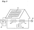
- Fig. 5 is a schematic view illustrating a conventional solar power generating system for domestic use.
- DC sources 101 comprising of a plurality of solar cells are placed on a house roof.
- DC output from the plurality of DC sources is accumulated and flowed into a connection box 102.
- the DC output from the connection box 102 is converted to AC output by an inverter 103, and is supplied to a load 105 as home electric appliance through a panelboard 104. Electricity can be also supplied to the loads 105 from a commercial power supply 106. When electricity runs short, for example at night, electric power is supplied from the commercial power supply 106.
- Patent Abstracts of Japan, publication number 06165513, for example, provides a method for operating a plurality of inverters in parallel and determining how many inverters should be operated by judging a total output current of inverters.
- the conventional procedure determines merely how many inverters should be operated on a basis of output current and does not take into consideration about which inverters should be operated. Accordingly, particular inverters work at a time of low output and the others work only at a time when output is increased. The particular inverters are operated longer than the other, resulting in shorter service life of that particular inverters than the others.
- the present invention was made to overcome this drawback.
- a device for operating inverters in the present invention comprises a plurality of inverters connected in parallel to a DC source, means for determining the number of inverters to be operated on a basis of AC output from the plurality of inverters or DC output from the DC source, and selection means for selecting the determined number of inverters to be operated among the plurality of inverters at random.
- the selection means includes a random number generation unit for calculating data on an inverter to be selected on a basis of information from the random number generation unit.
- the inverters are connected to the DC source through switches.
- the selection means controls the switches to turn ON or OFF.
- inverters to be operated can be selected at random from the plurality of inverters by selecting an inverter to be added or cut off among the plurality of inverters on a basis of the random number, preventing a particular inverter from working for a long period of time.
- a device for operating inverters in the present invention comprises a plurality of inverters connected in parallel to a DC source, means for determining the number of inverters to be operated on a basis of AC output from the plurality of inverters or DC output from the DC source, and selection means for selecting the determined number of inverters to be operated with less operating time among the plurality of inverters.
- the selection means includes storage means for storing data on the inverters' operating time and selects inverters to be operated by referring data in the storage means.
- the inverters are connected to the DC source through switches.
- the selection means controls the switches to turn ON or OFF.
- Inverters to be operated with less operating time are selected from the plurality of inverters. By selecting in such a manner, the determined number of inverters with less operating time are selected on a basis of operating time of each inverter among the plurality of inverters. Therefore, the operating time of each inverter becomes approximately equal, resulting in the prolonged service life of the power system.
- a device for operating inverters in the present invention comprises a plurality of inverters connected in parallel to a DC source, means for determining the number of inverters to be operated on a basis of AC output from the plurality of inverters or DC output from the DC source, and selection means for selecting the determined number of inverters to be operated with less output amount among the plurality of inverters.
- the selection means includes storage means for storing data on the inverters' output amount and selects inverters to be operated by referring data in the storage means.
- the inverters are connected to the DC source through switches.
- the selection means controls the switches to turn ON or OFF.
- Inverters to be operated with less output amount are selected from the plurality of inverters. By selecting in such a manner, the determined number of inverters with less output amount are selected among the plurality of inverters. Therefore, the frequency of operating each inverter becomes approximately equal, resulting in the prolonged service life of the power system.
- the determined number of inverters to be operated can be selected at random from the plurality of inverters. It can prevent a particular inverter from working for a long period of time and achieve a prolonged service life of the power system.
- a power system in the present invention having a DC source and a plurality of inverters connected in parallel to the DC source comprises means for determining the number of inverters to be operated on a basis of AC output from the plurality of inverters or DC output from the DC source, and selection means for selecting the determined number of inverters to be operated with less operating time among the plurality of inverters, and DC output from the DC source is converted to AC output to yield the AC output.
- the determined number of inverters to be operated with less operating time can be selected among the plurality of inverters. Therefore, operating time of each inverter becomes approximately equal, resulting in a prolonged service life of the power system.
- a power system in the present invention having a DC source and a plurality of inverters connected in parallel to a DC source comprises means for determining the number of inverters to be operated on a basis of AC output from the plurality of inverters or DC output from the DC source, and selection means for selecting the determined number of inverters to be operated with less output amount among the plurality of inverters, and DC output from the DC source is converted to AC output to yield the AC output.
- the determined number of inverters to be operated with less output amount can be selected from the plurality of inverters. Frequency of operating each inverter becomes approximately equal, resulting a prolonged service life of the power system.
- a power system according to the present invention is provided with failure judging means for judging a failure in each of the plurality of inverters.
- the determined number of inverters are selected from the plurality of inverters on a basis of a signal from the failure judging means.
- the power system according to the present invention is also provided with an alarm for giving the output result from the failure judging means.
- the system can be operated without using an failure inverter.
- a power system according to a first embodiment of the present invention will be described by referring to a block diagram as shown in Fig. 1. In this description, explanation will be made about a power system for 2kW.
- a power system comprises a DC source 1 including a plurality of solar cell modules, four units of inverters 11 - 14 for rated output of 500W which are connected in parallel with the DC source 1, and a control unit 2 for controlling each inverter.
- Selector switches 31 - 34 which respectively form pairs with inverters 11 - 14 are provided.
- a selector switch corresponding to the one of the inverters selected by the control unit turns ON to operate the inverter.
- AC output from the inverter is supplied to a load 5.
- the system may be connected with a commercial power supply (not illustrated).
- a measuring device 4 measures DC output from the DC source 1, and a signal from the measuring device 4 is sent to the control unit 2.
- the control unit 2 comprises an operation unit 21 for determining how many inverters should be operated on a basis of a signal from the measuring device 4, a selection unit 22 for selecting the determined number of inverters to be operated among the four inverters 11-14.
- the selection unit 22 includes a random number generation unit 23, and selects inverters to be operated at random among the plurality of inverters on a basis of an output result from the random number generation unit 23.
- the control unit 2 sends a control signal to a selector switch corresponding to an inverter selected by the control unit 23 in order to operate the equivalent inverter by turning the selector switch ON.
- FIG. 2 A procedure of controlling inverters in the control unit 2 is illustrated in the flow chart as Fig. 2.
- a measuring device 4 measures DC output from a DC source 1.
- the DC output from the DC source 1 which is fed from the measuring device 4 is sampled with sampling frequency such as a few msec to tens msec (Step 1).
- control unit obtains a differential coefficient for DC output in the last few minutes and judges whether the differential coefficient is increasing or not (Step 2).
- a differential coefficient influence of momentary changes of output power caused by weather change resulting from a shade of a cloud and a fitful wind can be prevented.
- Step 3 the control unit judges whether it is necessary to add an inverter to be operated. In specific, the control unit calculates a value of DC output at a next sampling in view of the differential coefficient, and judges adding an inverter to be operated is necessary when the calculated value exceeds the range of DC output which can be covered by the presently running inverters.
- two inverters are running at 950W of output power.
- the control unit judges that one inverter needs to be added since 1,050W is beyond the capacity of the presently running two inverters for 500W.
- the control unit judges that no inverter needs to be added since the current two inverters are sufficient.
- the control unit 2 makes a random selection of inverters to be operated from the inverters which are not running at present (Step 4).
- the control unit 2 sends a control signal to the selector switches corresponding to the selected inverter and turns the selector switch ON to operate the corresponding inverter.
- Step 1 This series of procedures forms a routine. After finishing these procedures, the routine is repeated from Step 1. When it is not necessary to add an inverter to be operated (NO in Step 3), this routine is also repeated from Step 1.
- Step 5 the control unit judges whether it is necessary to reduce the inverters to be operated. In judging it, as in Step 3, the control unit calculates a value of DC output at a next sampling in view of the differential coefficient, and judges reducing an inverter to be operated is necessary when the calculated value is below the range of DC output which can be covered by the less number of inverters than presently running.
- the control unit 2 makes a random selection of an inverter to be cut off from the inverters which are running at present (Step 6).
- the control unit 2 sends a control signal to the selector switch corresponding to the selected inverter and turn the selector switch OFF to stop operation of the corresponding inverter.
- Step 1 This series of procedures forms a routine. After finishing the procedures, the routine is repeated from Step 1. When it is not necessary to reduce an inverter to be operated (NO in Step 5), this routine is also repeated from Step 1.
- control unit makes a random selection of an inverter to be added or cut off among the plurality of inverters to make a random selection of the determined number of inverters determined by the operation unit 21 among the plurality of inverters. Therefore, no particular inverter works longer than others, resulting in prolonged service life of a power system.
- the measuring device measures DC output from the DC source 1 to determine the number of inverters to be operated.
- the control unit may measure AC output from the inverters 11 - 14, instead of the DC output, to determine the number of inverters to be operated.
- a failure judgment unit for judging a failure in the plurality of inverters is provided to feed a signal from the failure judgment unit to the control unit 2. It is preferred to select the determined number of inverters at random among the inverters except a failure inverter in accordance with a signal from the failure judgment unit.
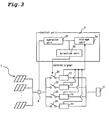
- FIG. 3 A power system according to a second embodiment of the present invention will be described by referring to a block diagram as shown in Fig. 3. It should be noted that the same reference numerals shown in Fig. 1 will be employed as those for denoting the same elements.
- a power system in the second embodiment is different from the first embodiment in the following points.
- the power system in the second embodiment has a control unit 2 provided with a storage unit 24 for storing each operating time of a plurality of inverters 11 - 14.
- the number of inverters to be operated is determined by an operation unit 21, and a selection unit 25 selects the determined number of inverters with less operating time on a basis of data stored in the storage unit 24.
- the control unit 2 controls operating time of the running inverters 11 - 14 and makes the storage unit 24 store the operating time as the data.
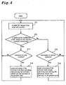
- FIG. 4 A procedure of controlling inverters in the control unit 2 is illustrated in a flow chart as Fig. 4.
- a measuring device 4 measures DC output from the DC source 1.
- the DC output from the DC source 1 which is fed from the measuring device 4 is sampled with sampling frequency such as a few msec to tens msec (Step 11).
- control unit 2 obtains a differential coefficient of DC output in the last few minutes and judges whether the differential coefficient is increasing or not (Step 12).
- a differential coefficient influence of momentary changes of output power caused by weather change resulting from a shade of a cloud and a fitful wind can be prevented.
- Step 13 the control unit 2 judges whether it is necessary to add an inverter to be operated. As in the first embodiment, the control unit calculates DC output at a next sampling in view of the differential coefficient, and judges adding an inverter to be operated is necessary when the calculated value exceeds the range of DC output which can be covered by the presently running inverters.
- the control unit 2 makes a selection of inverters to be run from the inverters which have worked for less time than the others by referring the data from the storage unit 24 (Step 14).
- the control unit 2 sends a control signal to the selector switch corresponding to the selected inverter and turns the selector switch ON to operate the corresponding inverter.
- Step 11 This series of procedures forms a routine. After finishing these procedures, the routine is repeated from Step 11. When it is not necessary to add an inverter to be operated (NO in Step 13), this routine is also repeated from Step 11.
- Step 15 the control unit 2 judges whether it is necessary to reduce the inverters to be operated. In judging it, as in the first embodiment, the control unit 2 calculates DC output at a next sampling in view of the differential coefficient, and judges reducing an inverter to be operated is necessary when the calculated value is below the range of DC output which can be covered by the less number of inverters than presently running.
- the control unit 2 makes a selection of an inverter to be cut off from the presently running inverters with longer operation time by referring the data in the storage unit 24 (Step 16).
- the control unit 2 sends a control signal to the selector switches corresponding to the selected inverter and turns the selector switch OFF to stop operation of the inverter.
- Step 11 This series of procedures forms a routine. After finishing the procedures, the routine is repeated from Step 11. When it is not necessary to reduce an inverter to be operated (NO in Step 15), this routine is also repeated from Step 11.
- the selection unit 25 selects an inverter to be operated with less operating time among a plurality of inverters and selects an inverter to be cut off with longer operating time from the presently operating inverters.
- the determined number of inverters determined by the operation unit 21 can be selected from a plurality of inverters with less operation time. Therefore, operating time of each inverter become approximately equal, resulting in prolonged service life of the power system.
- the measuring device 4 measures DC output from the DC source 1 to determine the number of inverters to be operated.
- the control unit may measure AC output from the inverters 11 - 14, instead of the DC output, to determine the number of inverters to be operated.
- the determined number of inverters are selected by referring the data on operating time of each inverter stored in the storing portion 24.
- the storing portion 24 stores the information on an amount of power output from each inverter instead of its operating time in order to select an inverter with less output amountto be operated on the basis of a power output amount.
- a failure judgment unit for judging a failure in the plurality of inverters is preferably provided to feed a signal to the control unit 2. It is preferred to select the determined number of inverters among the inverters with less operation time or less output amount except a failure inverter in accordance with a signal from the failure judgment unit.
- the present invention is applicable to power systems applied to other types of DC sources, such as a fuel cell and wind power generation, although the first and second embodiments describe a power system applied to a solar cell.
- the present invention is not limited to a system for 2kW, but applicable to power system for 1kW or 3kW etc..
- the present invention is applicable to any types of AC/DC inverters, not limited to a single- or three-phase type.
- inverters By operating inverters as described above, all of the inverters can be operated with approximately equal frequency without relying on a particular inverter. Therefore, it prevents the particular inverter from being out of life earlier than the others, which makes it possible to prolong the service life of the whole system.
- the power system according to the present invention can operate each inverter with approximately equal frequency. Therefore, it is possible to provide a power system with long service life.
Applications Claiming Priority (2)
| Application Number | Priority Date | Filing Date | Title |
|---|---|---|---|
| JP14146598 | 1998-05-22 | ||
| JP14146598A JP3545203B2 (ja) | 1998-05-22 | 1998-05-22 | インバータの運転方法及び電源システム |
Publications (3)
| Publication Number | Publication Date |
|---|---|
| EP0959552A2 true EP0959552A2 (fr) | 1999-11-24 |
| EP0959552A3 EP0959552A3 (fr) | 2001-04-04 |
| EP0959552B1 EP0959552B1 (fr) | 2013-11-27 |
Family
ID=15292525
Family Applications (1)
| Application Number | Title | Priority Date | Filing Date |
|---|---|---|---|
| EP99109949.0A Expired - Lifetime EP0959552B1 (fr) | 1998-05-22 | 1999-05-20 | Dispositif pour contrôler des onduleurs et système d'alimentation |
Country Status (3)
| Country | Link |
|---|---|
| US (2) | US6175512B1 (fr) |
| EP (1) | EP0959552B1 (fr) |
| JP (1) | JP3545203B2 (fr) |
Cited By (13)
| Publication number | Priority date | Publication date | Assignee | Title |
|---|---|---|---|---|
| DE10061724A1 (de) * | 2000-04-13 | 2002-03-07 | Bernhard Beck | Anlage zur Einspeisung von Strom aus Gleichstromerzeugern in das Wechselstromnetz |
| DE102006024482A1 (de) * | 2006-05-26 | 2007-12-06 | Powerlynx A/S | Verfahren zur Steuerung eines Leistungswandlers und elektrisches System, das dieses Verfahren anwendet |
| EP2008860A2 (fr) | 2007-06-25 | 2008-12-31 | Mazda Motor Corporation | Contrôle pour véhicule hybride |
| DE102007054647A1 (de) * | 2007-11-15 | 2009-06-18 | Siemens Ag | Solarwechselrichter mit mehreren parallel geschalteten Einzelwechselrichtern und mit einer übergeordneten elektronischen Steuereinheit |
| WO2009140548A2 (fr) | 2008-05-14 | 2009-11-19 | National Semiconductor Corporation | Système et procédé pour un réseau d'onduleurs intelligents |
| DE102008056256A1 (de) * | 2008-11-06 | 2010-05-20 | Siemens Aktiengesellschaft | Wechselrichterparallelschaltung mit Lastausgleich |
| EP2355170A3 (fr) * | 2010-02-09 | 2012-05-02 | Markus Emmert | Commande pour installations photovoltaïques |
| CN102484393A (zh) * | 2009-09-16 | 2012-05-30 | 东芝三菱电机产业系统株式会社 | 功率转换系统及不间断供电电源系统 |
| EP2528181A1 (fr) * | 2010-10-29 | 2012-11-28 | Shanghai Ghrepower Energy Co., Ltd. | Système d'alimentation électrique avec intégration d'énergie éolienne, d'énergie solaire, de diesel et d'alimentation secteur |
| EP1592122A3 (fr) * | 2004-04-28 | 2013-04-17 | Daihen Corporation | Procédé de commande d'onduleur |
| CN104471851A (zh) * | 2012-03-30 | 2015-03-25 | 东芝三菱电机产业系统株式会社 | 功率转换装置 |
| EP3226399A1 (fr) * | 2016-03-30 | 2017-10-04 | Doosan Heavy Industries & Construction Co., Ltd. | Appareil pour entraîner et commander des convertisseurs et des modules d'élément de commutation dans un système de production d'énergie éolienne |
| WO2018206529A1 (fr) * | 2017-05-11 | 2018-11-15 | Philips Lighting Holding B.V. | Système et procédé de conversion de puissance |
Families Citing this family (101)
| Publication number | Priority date | Publication date | Assignee | Title |
|---|---|---|---|---|
| US6291764B1 (en) * | 1999-03-24 | 2001-09-18 | Sanyo Electronics Co., Ltd. | Photovoltaic power generation device |
| US6285572B1 (en) * | 1999-04-20 | 2001-09-04 | Sanyo Electric Co., Ltd. | Method of operating a power supply system having parallel-connected inverters, and power converting system |
| JP3829317B2 (ja) * | 1999-10-18 | 2006-10-04 | 株式会社ジーエス・ユアサコーポレーション | 系統連系インバータの運転装置および運転方法ならびに系統連系インバータを運転するためのプログラムを記録したコンピュータ読取可能な記録媒体 |
| US6738275B1 (en) * | 1999-11-10 | 2004-05-18 | Electromed Internationale Ltee. | High-voltage x-ray generator |
| JP2002044869A (ja) * | 2000-07-21 | 2002-02-08 | Matsushita Electric Ind Co Ltd | 電力変換装置 |
| JP2002142462A (ja) * | 2000-10-30 | 2002-05-17 | Canon Inc | 電力変換装置およびその盗難防止方法 |
| JP4714985B2 (ja) * | 2000-11-29 | 2011-07-06 | パナソニック株式会社 | 系統連系インバータ |
| JP2006512428A (ja) * | 2002-05-13 | 2006-04-13 | ポリフューエル・インコーポレイテッド | イオン伝導性ブロックコポリマー |
| US20040175598A1 (en) * | 2002-12-02 | 2004-09-09 | Bliven David C. | Fuel cell power supply for portable computing device and method for fuel cell power control |
| US7269036B2 (en) * | 2003-05-12 | 2007-09-11 | Siemens Vdo Automotive Corporation | Method and apparatus for adjusting wakeup time in electrical power converter systems and transformer isolation |
| EP1642355A4 (fr) | 2003-05-28 | 2015-05-27 | Beacon Power Llc | Convertisseur de puissance pour panneau solaire |
| WO2005015727A1 (fr) * | 2003-08-07 | 2005-02-17 | Fuji Electric Fa Components & Systems Co., Ltd. | Dispositif d'inverseur utile pour commander un moteur electrique |
| JP4575026B2 (ja) * | 2004-05-24 | 2010-11-04 | 株式会社ダイヘン | インバータ装置の制御方法 |
| US7248490B2 (en) * | 2004-06-17 | 2007-07-24 | Gaia Power Technologies, Inc. | Battery and inverter configuration with increased efficiency |
| US8013583B2 (en) * | 2004-07-01 | 2011-09-06 | Xslent Energy Technologies, Llc | Dynamic switch power converter |
| JP2006187071A (ja) * | 2004-12-27 | 2006-07-13 | Daihen Corp | インバータ装置の運転方法 |
| JP4606887B2 (ja) * | 2005-01-21 | 2011-01-05 | 株式会社ダイヘン | インバータ装置の運転方法 |
| AT501422B1 (de) * | 2005-02-10 | 2009-05-15 | Fronius Int Gmbh | Wechselrichtersystem zum einspeisen in ein 3-phasennetz sowie wechselrichteranlage für ein 3-phasennetz |
| US11881814B2 (en) | 2005-12-05 | 2024-01-23 | Solaredge Technologies Ltd. | Testing of a photovoltaic panel |
| US10693415B2 (en) | 2007-12-05 | 2020-06-23 | Solaredge Technologies Ltd. | Testing of a photovoltaic panel |
| JP4836679B2 (ja) * | 2006-06-16 | 2011-12-14 | 株式会社東芝 | 電気車用電源装置 |
| JP5199562B2 (ja) * | 2006-09-15 | 2013-05-15 | 株式会社マエカワ | 船舶機械駆動システム |
| US7893346B2 (en) * | 2006-09-28 | 2011-02-22 | Jack Nachamkin | Integrated voltaic energy system |
| JP4935314B2 (ja) * | 2006-11-16 | 2012-05-23 | シンフォニアテクノロジー株式会社 | 発電装置 |
| US11855231B2 (en) | 2006-12-06 | 2023-12-26 | Solaredge Technologies Ltd. | Distributed power harvesting systems using DC power sources |
| US8013472B2 (en) | 2006-12-06 | 2011-09-06 | Solaredge, Ltd. | Method for distributed power harvesting using DC power sources |
| US9112379B2 (en) | 2006-12-06 | 2015-08-18 | Solaredge Technologies Ltd. | Pairing of components in a direct current distributed power generation system |
| US11687112B2 (en) | 2006-12-06 | 2023-06-27 | Solaredge Technologies Ltd. | Distributed power harvesting systems using DC power sources |
| US11296650B2 (en) | 2006-12-06 | 2022-04-05 | Solaredge Technologies Ltd. | System and method for protection during inverter shutdown in distributed power installations |
| US11309832B2 (en) | 2006-12-06 | 2022-04-19 | Solaredge Technologies Ltd. | Distributed power harvesting systems using DC power sources |
| US11728768B2 (en) | 2006-12-06 | 2023-08-15 | Solaredge Technologies Ltd. | Pairing of components in a direct current distributed power generation system |
| US8816535B2 (en) | 2007-10-10 | 2014-08-26 | Solaredge Technologies, Ltd. | System and method for protection during inverter shutdown in distributed power installations |
| US9088178B2 (en) | 2006-12-06 | 2015-07-21 | Solaredge Technologies Ltd | Distributed power harvesting systems using DC power sources |
| US9130401B2 (en) | 2006-12-06 | 2015-09-08 | Solaredge Technologies Ltd. | Distributed power harvesting systems using DC power sources |
| US11569659B2 (en) | 2006-12-06 | 2023-01-31 | Solaredge Technologies Ltd. | Distributed power harvesting systems using DC power sources |
| US8963369B2 (en) | 2007-12-04 | 2015-02-24 | Solaredge Technologies Ltd. | Distributed power harvesting systems using DC power sources |
| US8384243B2 (en) | 2007-12-04 | 2013-02-26 | Solaredge Technologies Ltd. | Distributed power harvesting systems using DC power sources |
| US8947194B2 (en) | 2009-05-26 | 2015-02-03 | Solaredge Technologies Ltd. | Theft detection and prevention in a power generation system |
| US11888387B2 (en) | 2006-12-06 | 2024-01-30 | Solaredge Technologies Ltd. | Safety mechanisms, wake up and shutdown methods in distributed power installations |
| US8319471B2 (en) | 2006-12-06 | 2012-11-27 | Solaredge, Ltd. | Battery power delivery module |
| US11735910B2 (en) | 2006-12-06 | 2023-08-22 | Solaredge Technologies Ltd. | Distributed power system using direct current power sources |
| US8618692B2 (en) | 2007-12-04 | 2013-12-31 | Solaredge Technologies Ltd. | Distributed power system using direct current power sources |
| US8319483B2 (en) | 2007-08-06 | 2012-11-27 | Solaredge Technologies Ltd. | Digital average input current control in power converter |
| US8473250B2 (en) | 2006-12-06 | 2013-06-25 | Solaredge, Ltd. | Monitoring of distributed power harvesting systems using DC power sources |
| JP2008187865A (ja) * | 2007-01-31 | 2008-08-14 | Nagano Japan Radio Co | 充電装置 |
| US20080266758A1 (en) * | 2007-04-25 | 2008-10-30 | Hurt Steven B | Mobile utilities station |
| WO2008149393A1 (fr) * | 2007-06-06 | 2008-12-11 | Power-One Italy S.P.A. | Alimentation en puissance électrique à l'aide d'une pluralité d'inverseurs parallèles et procédé de commande basé sur le suivi de point de puissance maximale |
| JP4946854B2 (ja) * | 2007-06-25 | 2012-06-06 | マツダ株式会社 | ハイブリッド車両の制御装置および制御方法 |
| WO2009062117A1 (fr) * | 2007-11-09 | 2009-05-14 | Sunpreme, Inc. | Piles solaires à faible coût et procédés pour la fabrication de ces piles |
| US11264947B2 (en) | 2007-12-05 | 2022-03-01 | Solaredge Technologies Ltd. | Testing of a photovoltaic panel |
| US8049523B2 (en) | 2007-12-05 | 2011-11-01 | Solaredge Technologies Ltd. | Current sensing on a MOSFET |
| EP2232690B1 (fr) | 2007-12-05 | 2016-08-31 | Solaredge Technologies Ltd. | Onduleurs connectés en parallèle |
| CN101933209B (zh) | 2007-12-05 | 2015-10-21 | 太阳能安吉有限公司 | 分布式电力装置中的安全机构、醒来和关闭方法 |
| US9291696B2 (en) | 2007-12-05 | 2016-03-22 | Solaredge Technologies Ltd. | Photovoltaic system power tracking method |
| WO2009118682A2 (fr) | 2008-03-24 | 2009-10-01 | Solaredge Technolgies Ltd. | Commutation sous intensité nulle |
| WO2009136358A1 (fr) | 2008-05-05 | 2009-11-12 | Solaredge Technologies Ltd. | Circuit combinateur de puissance de courant continu |
| JP5160371B2 (ja) * | 2008-10-17 | 2013-03-13 | 本田技研工業株式会社 | 交流電力供給装置及びその制御方法 |
| US7951640B2 (en) * | 2008-11-07 | 2011-05-31 | Sunpreme, Ltd. | Low-cost multi-junction solar cells and methods for their production |
| US8796066B2 (en) | 2008-11-07 | 2014-08-05 | Sunpreme, Inc. | Low-cost solar cells and methods for fabricating low cost substrates for solar cells |
| WO2010114995A1 (fr) | 2009-04-01 | 2010-10-07 | Nextronex Energy Systems, Llc | Système solaire raccordé au réseau et procédé |
| ES2385912T3 (es) * | 2009-04-17 | 2012-08-03 | Sma Solar Technology Ag | Procedimiento y dispositivo para conectar una planta fotovoltaica a una red de corriente alterna |
| FR2945684B1 (fr) * | 2009-05-14 | 2011-06-17 | Commissariat Energie Atomique | Circuit convertisseur et systeme electronique comportant un tel circuit |
| US8259478B2 (en) * | 2009-06-12 | 2012-09-04 | J Neva Devi Capra | Power inverter |
| JP5591247B2 (ja) * | 2009-09-16 | 2014-09-17 | 東芝三菱電機産業システム株式会社 | 電力変換システムおよび無停電電源システム |
| TWI397805B (zh) * | 2009-11-11 | 2013-06-01 | Giga Byte Tech Co Ltd | 電路系統及其控制方法 |
| FR2953996B1 (fr) * | 2009-12-11 | 2012-01-20 | Centre Nat Rech Scient | Systeme de gestion electronique de cellules photovoltaiques fonction de la meteorologie |
| FR2953997B1 (fr) | 2009-12-11 | 2012-01-20 | Centre Nat Rech Scient | Systeme de gestion electronique de cellules photovoltaiques avec seuils adaptes |
| WO2011139833A2 (fr) * | 2010-04-29 | 2011-11-10 | Enphase Energy, Inc. | Procédé et appareil pour production d'énergie répartie |
| US10673222B2 (en) | 2010-11-09 | 2020-06-02 | Solaredge Technologies Ltd. | Arc detection and prevention in a power generation system |
| US10673229B2 (en) | 2010-11-09 | 2020-06-02 | Solaredge Technologies Ltd. | Arc detection and prevention in a power generation system |
| GB2485527B (en) | 2010-11-09 | 2012-12-19 | Solaredge Technologies Ltd | Arc detection and prevention in a power generation system |
| US10230310B2 (en) | 2016-04-05 | 2019-03-12 | Solaredge Technologies Ltd | Safety switch for photovoltaic systems |
| US9118213B2 (en) * | 2010-11-24 | 2015-08-25 | Kohler Co. | Portal for harvesting energy from distributed electrical power sources |
| GB2486408A (en) | 2010-12-09 | 2012-06-20 | Solaredge Technologies Ltd | Disconnection of a string carrying direct current |
| WO2012086825A1 (fr) * | 2010-12-21 | 2012-06-28 | 日本電気株式会社 | Dispositif et procédé de charge |
| GB2483317B (en) | 2011-01-12 | 2012-08-22 | Solaredge Technologies Ltd | Serially connected inverters |
| FR2972085B1 (fr) * | 2011-02-25 | 2015-01-16 | Valeo Sys Controle Moteur Sas | Dispositif de conversion d'energie et procede de repartition associe |
| US8570005B2 (en) | 2011-09-12 | 2013-10-29 | Solaredge Technologies Ltd. | Direct current link circuit |
| US20130088900A1 (en) * | 2011-10-10 | 2013-04-11 | Jong-Ho Park | Energy storage system and controlling method of the same |
| TWI448034B (zh) * | 2011-12-19 | 2014-08-01 | Darfon Electronics Corp | 太陽能換流器系統及其控制方法 |
| GB2498365A (en) | 2012-01-11 | 2013-07-17 | Solaredge Technologies Ltd | Photovoltaic module |
| GB2498790A (en) | 2012-01-30 | 2013-07-31 | Solaredge Technologies Ltd | Maximising power in a photovoltaic distributed power system |
| GB2498791A (en) | 2012-01-30 | 2013-07-31 | Solaredge Technologies Ltd | Photovoltaic panel circuitry |
| US9853565B2 (en) | 2012-01-30 | 2017-12-26 | Solaredge Technologies Ltd. | Maximized power in a photovoltaic distributed power system |
| GB2499991A (en) | 2012-03-05 | 2013-09-11 | Solaredge Technologies Ltd | DC link circuit for photovoltaic array |
| US10115841B2 (en) | 2012-06-04 | 2018-10-30 | Solaredge Technologies Ltd. | Integrated photovoltaic panel circuitry |
| JP6082886B2 (ja) * | 2013-02-22 | 2017-02-22 | 株式会社高砂製作所 | 電力調整装置及び電力調整方法 |
| US9548619B2 (en) | 2013-03-14 | 2017-01-17 | Solaredge Technologies Ltd. | Method and apparatus for storing and depleting energy |
| US9941813B2 (en) | 2013-03-14 | 2018-04-10 | Solaredge Technologies Ltd. | High frequency multi-level inverter |
| EP3506370B1 (fr) | 2013-03-15 | 2023-12-20 | Solaredge Technologies Ltd. | Mécanisme de dérivation |
| US9318974B2 (en) | 2014-03-26 | 2016-04-19 | Solaredge Technologies Ltd. | Multi-level inverter with flying capacitor topology |
| WO2016065241A1 (fr) | 2014-10-24 | 2016-04-28 | Enphase Energy, Inc. | Système de batterie en parallèle |
| JP6466186B2 (ja) | 2015-02-02 | 2019-02-06 | 株式会社東芝 | 変調信号生成装置及び無線装置 |
| JPWO2017122323A1 (ja) * | 2016-01-14 | 2018-03-22 | 三菱電機株式会社 | 発電制御システムおよび出力制御配分ユニット |
| JP6538585B2 (ja) | 2016-02-17 | 2019-07-03 | 株式会社東芝 | 変調信号生成装置および無線装置 |
| US11177663B2 (en) | 2016-04-05 | 2021-11-16 | Solaredge Technologies Ltd. | Chain of power devices |
| US11018623B2 (en) | 2016-04-05 | 2021-05-25 | Solaredge Technologies Ltd. | Safety switch for photovoltaic systems |
| KR101816226B1 (ko) * | 2016-04-29 | 2018-01-08 | 엘에스산전 주식회사 | 복수 인버터 제어장치 및 이를 적용한 인버터 시스템 |
| CN109690932B (zh) * | 2016-09-12 | 2020-03-13 | 株式会社村田制作所 | 电源装置 |
| JP6213645B1 (ja) * | 2016-09-27 | 2017-10-18 | 株式会社デンソーファシリティーズ | 制御装置 |
| JP7102839B2 (ja) * | 2018-03-26 | 2022-07-20 | トヨタ自動車株式会社 | 車両用ソーラー発電システム |
Family Cites Families (11)
| Publication number | Priority date | Publication date | Assignee | Title |
|---|---|---|---|---|
| JPS61135366A (ja) * | 1984-12-05 | 1986-06-23 | Kyocera Corp | 電力変換装置の制御方式 |
| US4636931A (en) * | 1985-06-28 | 1987-01-13 | Shikoku Denryoku Kabushiki Kaisha | Photovoltaic power control system |
| CA2074176A1 (fr) * | 1990-11-19 | 1992-05-20 | Ronald Rohner | Methode et dispositif de commutation d'inverseurs en parallele |
| JP3112584B2 (ja) * | 1992-11-18 | 2000-11-27 | 東芝エフエーシステムエンジニアリング株式会社 | インバータの高効率運転装置 |
| JP3254839B2 (ja) * | 1993-08-27 | 2002-02-12 | 富士電機株式会社 | 系統連系用インバータの並列運転制御方法 |
| US5563780A (en) * | 1993-12-08 | 1996-10-08 | International Power Systems, Inc. | Power conversion array applying small sequentially switched converters in parallel |
| US5508497A (en) * | 1994-02-02 | 1996-04-16 | Abb Patent Gmbh | Method for open-loop/closed-loop control of at least two parallel oscillating circuit inverters feeding induction furnaces |
| JPH0870533A (ja) * | 1994-08-26 | 1996-03-12 | Omron Corp | 太陽電池を用いた電源装置 |
| JPH0991049A (ja) * | 1995-09-22 | 1997-04-04 | Toshiba Corp | 太陽光発電システム |
| JP3534914B2 (ja) * | 1995-10-31 | 2004-06-07 | 京セラ株式会社 | 電力供給装置 |
| US5896281A (en) * | 1997-07-02 | 1999-04-20 | Raytheon Company | Power conditioning system for a four quadrant photovoltaic array with an inverter for each array quadrant |
-
1998
- 1998-05-22 JP JP14146598A patent/JP3545203B2/ja not_active Expired - Fee Related
-
1999
- 1999-05-19 US US09/313,969 patent/US6175512B1/en not_active Expired - Lifetime
- 1999-05-20 EP EP99109949.0A patent/EP0959552B1/fr not_active Expired - Lifetime
-
2000
- 2000-10-19 US US09/691,136 patent/US6252785B1/en not_active Expired - Lifetime
Non-Patent Citations (1)
| Title |
|---|
| None |
Cited By (26)
| Publication number | Priority date | Publication date | Assignee | Title |
|---|---|---|---|---|
| DE10061724A1 (de) * | 2000-04-13 | 2002-03-07 | Bernhard Beck | Anlage zur Einspeisung von Strom aus Gleichstromerzeugern in das Wechselstromnetz |
| EP1592122A3 (fr) * | 2004-04-28 | 2013-04-17 | Daihen Corporation | Procédé de commande d'onduleur |
| DE102006024482A1 (de) * | 2006-05-26 | 2007-12-06 | Powerlynx A/S | Verfahren zur Steuerung eines Leistungswandlers und elektrisches System, das dieses Verfahren anwendet |
| US7940018B2 (en) | 2007-06-25 | 2011-05-10 | Mazda Motor Corporation | Control system for a hybrid electric vehicle and a method for controlling a hybrid electric vehicle |
| EP2008860A2 (fr) | 2007-06-25 | 2008-12-31 | Mazda Motor Corporation | Contrôle pour véhicule hybride |
| EP2008860A3 (fr) * | 2007-06-25 | 2009-02-18 | Mazda Motor Corporation | Contrôle pour véhicule hybride |
| DE102007054647A1 (de) * | 2007-11-15 | 2009-06-18 | Siemens Ag | Solarwechselrichter mit mehreren parallel geschalteten Einzelwechselrichtern und mit einer übergeordneten elektronischen Steuereinheit |
| WO2009140548A2 (fr) | 2008-05-14 | 2009-11-19 | National Semiconductor Corporation | Système et procédé pour un réseau d'onduleurs intelligents |
| EP2291908A4 (fr) * | 2008-05-14 | 2015-05-20 | Nat Semiconductor Corp | Système et procédé pour un réseau d'onduleurs intelligents |
| DE102008056256A1 (de) * | 2008-11-06 | 2010-05-20 | Siemens Aktiengesellschaft | Wechselrichterparallelschaltung mit Lastausgleich |
| CN102484393A (zh) * | 2009-09-16 | 2012-05-30 | 东芝三菱电机产业系统株式会社 | 功率转换系统及不间断供电电源系统 |
| CN102484393B (zh) * | 2009-09-16 | 2015-11-25 | 东芝三菱电机产业系统株式会社 | 功率转换系统及不间断供电电源系统 |
| US9093861B2 (en) | 2009-09-16 | 2015-07-28 | Toshiba Mitsubishi-Electric Industrial Systems Corporation | Power conversion system and uninterruptible power supply system |
| EP2355170A3 (fr) * | 2010-02-09 | 2012-05-02 | Markus Emmert | Commande pour installations photovoltaïques |
| EP2528181A1 (fr) * | 2010-10-29 | 2012-11-28 | Shanghai Ghrepower Energy Co., Ltd. | Système d'alimentation électrique avec intégration d'énergie éolienne, d'énergie solaire, de diesel et d'alimentation secteur |
| EP2528181A4 (fr) * | 2010-10-29 | 2015-04-08 | Shanghai Ghrepower Green Energy Co Ltd | Système d'alimentation électrique avec intégration d'énergie éolienne, d'énergie solaire, de diesel et d'alimentation secteur |
| US9130387B2 (en) | 2010-10-29 | 2015-09-08 | Shanghai Ghrepower Green Energy Company Ltd. Of P.R. China | Hybrid integrated wind-solar-diesel-city power supply system |
| CN104471851A (zh) * | 2012-03-30 | 2015-03-25 | 东芝三菱电机产业系统株式会社 | 功率转换装置 |
| EP2833540A4 (fr) * | 2012-03-30 | 2016-01-27 | Toshiba Mitsubishi Elec Inc | Dispositif de conversion électrique |
| CN104471851B (zh) * | 2012-03-30 | 2017-06-06 | 东芝三菱电机产业系统株式会社 | 功率转换装置 |
| EP3226399A1 (fr) * | 2016-03-30 | 2017-10-04 | Doosan Heavy Industries & Construction Co., Ltd. | Appareil pour entraîner et commander des convertisseurs et des modules d'élément de commutation dans un système de production d'énergie éolienne |
| US10669989B2 (en) | 2016-03-30 | 2020-06-02 | DOOSAN Heavy Industries Construction Co., LTD | Apparatus for driving and controlling converters and switching element modules in a wind power generation system |
| WO2018206529A1 (fr) * | 2017-05-11 | 2018-11-15 | Philips Lighting Holding B.V. | Système et procédé de conversion de puissance |
| CN110582736A (zh) * | 2017-05-11 | 2019-12-17 | 昕诺飞控股有限公司 | 功率转换系统和方法 |
| US11139658B2 (en) | 2017-05-11 | 2021-10-05 | Signify Holding B.V. | Power conversion system and method |
| CN110582736B (zh) * | 2017-05-11 | 2022-03-22 | 昕诺飞控股有限公司 | 功率转换系统和方法 |
Also Published As
| Publication number | Publication date |
|---|---|
| EP0959552B1 (fr) | 2013-11-27 |
| US6252785B1 (en) | 2001-06-26 |
| JP3545203B2 (ja) | 2004-07-21 |
| EP0959552A3 (fr) | 2001-04-04 |
| US6175512B1 (en) | 2001-01-16 |
| JPH11341816A (ja) | 1999-12-10 |
Similar Documents
| Publication | Publication Date | Title |
|---|---|---|
| US6252785B1 (en) | Device for operating inverter and power system | |
| US9455574B2 (en) | Power distribution system | |
| US9496725B2 (en) | Power control apparatus, method, program, and integrated circuit, and storage battery unit | |
| JP5584763B2 (ja) | 直流配電システム | |
| RU2692083C1 (ru) | Устройство управления энергоснабжением для жилых домов, коммерческих и промышленных объектов с использованием сетевых, вспомогательных и возобновляемых источников электрической энергии и их комбинаций и способ интеллектуального управления подключением источников электроэнергии | |
| US6285572B1 (en) | Method of operating a power supply system having parallel-connected inverters, and power converting system | |
| EP2337184A2 (fr) | Système de stockage d'énergie raccordé au réseau et son procédé de commande | |
| WO2007086472A1 (fr) | Système d'alimentation | |
| JP2002315197A (ja) | ハイブリッド電源システム及びその運転方法 | |
| JP4293673B2 (ja) | 複数のインバータを有する電源システムの運転方法 | |
| JPH11178237A (ja) | 家庭用電力供給システム | |
| WO2014043016A1 (fr) | Procédé et appareil de production bidirectionnelle d'électricité dans un module de puissance | |
| EP4246751A1 (fr) | Procédé de contrôle d'un système de stockage d'énergie de batterie d'un système électrique avec des charges dynamiques élevées | |
| JP5070882B2 (ja) | 電力供給システムおよび電力供給方法 | |
| JP5841279B2 (ja) | 電力充電供給装置 | |
| JP3756020B2 (ja) | 電力管理装置 | |
| EP2797198A1 (fr) | Dispositif de charge et de décharge et système de charge et de décharge l'utilisant | |
| WO2023027137A1 (fr) | Dispositif de commande d'énergie, système de commande d'énergie et procédé de commande d'énergie | |
| JPH05252671A (ja) | 太陽光発電出力制御方式 | |
| CN114725929A (zh) | 一种用于风光储微网系统的能量管理控制方法及其系统 | |
| JP2003116224A (ja) | 太陽光発電システム及びその電力変換装置、並びに該システムの制御方法 | |
| RU2726943C1 (ru) | Способ снижения расхода топлива дизель-генераторными установками в гибридной электростанции с возобновляемыми источниками энергии | |
| JP2004265778A (ja) | 電力供給システム、及び燃料電池ユニット | |
| JPH0946912A (ja) | 分散形電源装置 | |
| WO2023175795A1 (fr) | Dispositif de commande, procédé de commande, support de stockage et programme |
Legal Events
| Date | Code | Title | Description |
|---|---|---|---|
| PUAI | Public reference made under article 153(3) epc to a published international application that has entered the european phase |
Free format text: ORIGINAL CODE: 0009012 |
|
| AK | Designated contracting states |
Kind code of ref document: A2 Designated state(s): DE IT NL |
|
| AX | Request for extension of the european patent |
Free format text: AL;LT;LV;MK;RO;SI |
|
| PUAL | Search report despatched |
Free format text: ORIGINAL CODE: 0009013 |
|
| AK | Designated contracting states |
Kind code of ref document: A3 Designated state(s): AT BE CH CY DE DK ES FI FR GB GR IE IT LI LU MC NL PT SE |
|
| AX | Request for extension of the european patent |
Free format text: AL;LT;LV;MK;RO;SI |
|
| 17P | Request for examination filed |
Effective date: 20010425 |
|
| AKX | Designation fees paid |
Free format text: DE IT NL |
|
| 17Q | First examination report despatched |
Effective date: 20091119 |
|
| GRAP | Despatch of communication of intention to grant a patent |
Free format text: ORIGINAL CODE: EPIDOSNIGR1 |
|
| INTG | Intention to grant announced |
Effective date: 20130624 |
|
| GRAS | Grant fee paid |
Free format text: ORIGINAL CODE: EPIDOSNIGR3 |
|
| GRAA | (expected) grant |
Free format text: ORIGINAL CODE: 0009210 |
|
| AK | Designated contracting states |
Kind code of ref document: B1 Designated state(s): DE IT NL |
|
| REG | Reference to a national code |
Ref country code: DE Ref legal event code: R096 Ref document number: 69944945 Country of ref document: DE Effective date: 20140116 |
|
| REG | Reference to a national code |
Ref country code: NL Ref legal event code: VDEP Effective date: 20131127 |
|
| PG25 | Lapsed in a contracting state [announced via postgrant information from national office to epo] |
Ref country code: NL Free format text: LAPSE BECAUSE OF FAILURE TO SUBMIT A TRANSLATION OF THE DESCRIPTION OR TO PAY THE FEE WITHIN THE PRESCRIBED TIME-LIMIT Effective date: 20131127 |
|
| REG | Reference to a national code |
Ref country code: DE Ref legal event code: R097 Ref document number: 69944945 Country of ref document: DE |
|
| PLBE | No opposition filed within time limit |
Free format text: ORIGINAL CODE: 0009261 |
|
| STAA | Information on the status of an ep patent application or granted ep patent |
Free format text: STATUS: NO OPPOSITION FILED WITHIN TIME LIMIT |
|
| 26N | No opposition filed |
Effective date: 20140828 |
|
| REG | Reference to a national code |
Ref country code: DE Ref legal event code: R097 Ref document number: 69944945 Country of ref document: DE Effective date: 20140828 |
|
| REG | Reference to a national code |
Ref country code: DE Ref legal event code: R082 Ref document number: 69944945 Country of ref document: DE Representative=s name: GLAWE DELFS MOLL PARTNERSCHAFT MBB VON PATENT-, DE Ref country code: DE Ref legal event code: R082 Ref document number: 69944945 Country of ref document: DE |
|
| PG25 | Lapsed in a contracting state [announced via postgrant information from national office to epo] |
Ref country code: IT Free format text: LAPSE BECAUSE OF FAILURE TO SUBMIT A TRANSLATION OF THE DESCRIPTION OR TO PAY THE FEE WITHIN THE PRESCRIBED TIME-LIMIT Effective date: 20131127 |
|
| PGFP | Annual fee paid to national office [announced via postgrant information from national office to epo] |
Ref country code: DE Payment date: 20160520 Year of fee payment: 18 |
|
| REG | Reference to a national code |
Ref country code: DE Ref legal event code: R119 Ref document number: 69944945 Country of ref document: DE |
|
| PG25 | Lapsed in a contracting state [announced via postgrant information from national office to epo] |
Ref country code: DE Free format text: LAPSE BECAUSE OF NON-PAYMENT OF DUE FEES Effective date: 20171201 |