EP2337184A2 - Système de stockage d'énergie raccordé au réseau et son procédé de commande - Google Patents
Système de stockage d'énergie raccordé au réseau et son procédé de commande Download PDFInfo
- Publication number
- EP2337184A2 EP2337184A2 EP20100252115 EP10252115A EP2337184A2 EP 2337184 A2 EP2337184 A2 EP 2337184A2 EP 20100252115 EP20100252115 EP 20100252115 EP 10252115 A EP10252115 A EP 10252115A EP 2337184 A2 EP2337184 A2 EP 2337184A2
- Authority
- EP
- European Patent Office
- Prior art keywords
- power generation
- power
- generation modules
- generated
- reference value
- Prior art date
- Legal status (The legal status is an assumption and is not a legal conclusion. Google has not performed a legal analysis and makes no representation as to the accuracy of the status listed.)
- Withdrawn
Links
Images


Classifications
-
- H—ELECTRICITY
- H02—GENERATION; CONVERSION OR DISTRIBUTION OF ELECTRIC POWER
- H02J—CIRCUIT ARRANGEMENTS OR SYSTEMS FOR SUPPLYING OR DISTRIBUTING ELECTRIC POWER; SYSTEMS FOR STORING ELECTRIC ENERGY
- H02J3/00—Circuit arrangements for ac mains or ac distribution networks
- H02J3/38—Arrangements for parallely feeding a single network by two or more generators, converters or transformers
-
- H—ELECTRICITY
- H02—GENERATION; CONVERSION OR DISTRIBUTION OF ELECTRIC POWER
- H02J—CIRCUIT ARRANGEMENTS OR SYSTEMS FOR SUPPLYING OR DISTRIBUTING ELECTRIC POWER; SYSTEMS FOR STORING ELECTRIC ENERGY
- H02J7/00—Circuit arrangements for charging or depolarising batteries or for supplying loads from batteries
- H02J7/34—Parallel operation in networks using both storage and other dc sources, e.g. providing buffering
- H02J7/35—Parallel operation in networks using both storage and other dc sources, e.g. providing buffering with light sensitive cells
-
- H—ELECTRICITY
- H02—GENERATION; CONVERSION OR DISTRIBUTION OF ELECTRIC POWER
- H02J—CIRCUIT ARRANGEMENTS OR SYSTEMS FOR SUPPLYING OR DISTRIBUTING ELECTRIC POWER; SYSTEMS FOR STORING ELECTRIC ENERGY
- H02J3/00—Circuit arrangements for ac mains or ac distribution networks
- H02J3/28—Arrangements for balancing of the load in a network by storage of energy
- H02J3/32—Arrangements for balancing of the load in a network by storage of energy using batteries with converting means
-
- H—ELECTRICITY
- H02—GENERATION; CONVERSION OR DISTRIBUTION OF ELECTRIC POWER
- H02J—CIRCUIT ARRANGEMENTS OR SYSTEMS FOR SUPPLYING OR DISTRIBUTING ELECTRIC POWER; SYSTEMS FOR STORING ELECTRIC ENERGY
- H02J3/00—Circuit arrangements for ac mains or ac distribution networks
- H02J3/38—Arrangements for parallely feeding a single network by two or more generators, converters or transformers
- H02J3/381—Dispersed generators
-
- H—ELECTRICITY
- H02—GENERATION; CONVERSION OR DISTRIBUTION OF ELECTRIC POWER
- H02J—CIRCUIT ARRANGEMENTS OR SYSTEMS FOR SUPPLYING OR DISTRIBUTING ELECTRIC POWER; SYSTEMS FOR STORING ELECTRIC ENERGY
- H02J3/00—Circuit arrangements for ac mains or ac distribution networks
- H02J3/38—Arrangements for parallely feeding a single network by two or more generators, converters or transformers
- H02J3/46—Controlling of the sharing of output between the generators, converters, or transformers
-
- H—ELECTRICITY
- H02—GENERATION; CONVERSION OR DISTRIBUTION OF ELECTRIC POWER
- H02J—CIRCUIT ARRANGEMENTS OR SYSTEMS FOR SUPPLYING OR DISTRIBUTING ELECTRIC POWER; SYSTEMS FOR STORING ELECTRIC ENERGY
- H02J9/00—Circuit arrangements for emergency or stand-by power supply, e.g. for emergency lighting
- H02J9/04—Circuit arrangements for emergency or stand-by power supply, e.g. for emergency lighting in which the distribution system is disconnected from the normal source and connected to a standby source
- H02J9/06—Circuit arrangements for emergency or stand-by power supply, e.g. for emergency lighting in which the distribution system is disconnected from the normal source and connected to a standby source with automatic change-over, e.g. UPS systems
- H02J9/062—Circuit arrangements for emergency or stand-by power supply, e.g. for emergency lighting in which the distribution system is disconnected from the normal source and connected to a standby source with automatic change-over, e.g. UPS systems for AC powered loads
-
- H—ELECTRICITY
- H02—GENERATION; CONVERSION OR DISTRIBUTION OF ELECTRIC POWER
- H02J—CIRCUIT ARRANGEMENTS OR SYSTEMS FOR SUPPLYING OR DISTRIBUTING ELECTRIC POWER; SYSTEMS FOR STORING ELECTRIC ENERGY
- H02J2300/00—Systems for supplying or distributing electric power characterised by decentralized, dispersed, or local generation
- H02J2300/20—The dispersed energy generation being of renewable origin
- H02J2300/22—The renewable source being solar energy
- H02J2300/24—The renewable source being solar energy of photovoltaic origin
-
- Y—GENERAL TAGGING OF NEW TECHNOLOGICAL DEVELOPMENTS; GENERAL TAGGING OF CROSS-SECTIONAL TECHNOLOGIES SPANNING OVER SEVERAL SECTIONS OF THE IPC; TECHNICAL SUBJECTS COVERED BY FORMER USPC CROSS-REFERENCE ART COLLECTIONS [XRACs] AND DIGESTS
- Y02—TECHNOLOGIES OR APPLICATIONS FOR MITIGATION OR ADAPTATION AGAINST CLIMATE CHANGE
- Y02B—CLIMATE CHANGE MITIGATION TECHNOLOGIES RELATED TO BUILDINGS, e.g. HOUSING, HOUSE APPLIANCES OR RELATED END-USER APPLICATIONS
- Y02B10/00—Integration of renewable energy sources in buildings
- Y02B10/70—Hybrid systems, e.g. uninterruptible or back-up power supplies integrating renewable energies
-
- Y—GENERAL TAGGING OF NEW TECHNOLOGICAL DEVELOPMENTS; GENERAL TAGGING OF CROSS-SECTIONAL TECHNOLOGIES SPANNING OVER SEVERAL SECTIONS OF THE IPC; TECHNICAL SUBJECTS COVERED BY FORMER USPC CROSS-REFERENCE ART COLLECTIONS [XRACs] AND DIGESTS
- Y02—TECHNOLOGIES OR APPLICATIONS FOR MITIGATION OR ADAPTATION AGAINST CLIMATE CHANGE
- Y02E—REDUCTION OF GREENHOUSE GAS [GHG] EMISSIONS, RELATED TO ENERGY GENERATION, TRANSMISSION OR DISTRIBUTION
- Y02E10/00—Energy generation through renewable energy sources
- Y02E10/50—Photovoltaic [PV] energy
- Y02E10/56—Power conversion systems, e.g. maximum power point trackers
-
- Y—GENERAL TAGGING OF NEW TECHNOLOGICAL DEVELOPMENTS; GENERAL TAGGING OF CROSS-SECTIONAL TECHNOLOGIES SPANNING OVER SEVERAL SECTIONS OF THE IPC; TECHNICAL SUBJECTS COVERED BY FORMER USPC CROSS-REFERENCE ART COLLECTIONS [XRACs] AND DIGESTS
- Y02—TECHNOLOGIES OR APPLICATIONS FOR MITIGATION OR ADAPTATION AGAINST CLIMATE CHANGE
- Y02E—REDUCTION OF GREENHOUSE GAS [GHG] EMISSIONS, RELATED TO ENERGY GENERATION, TRANSMISSION OR DISTRIBUTION
- Y02E70/00—Other energy conversion or management systems reducing GHG emissions
- Y02E70/30—Systems combining energy storage with energy generation of non-fossil origin
-
- Y—GENERAL TAGGING OF NEW TECHNOLOGICAL DEVELOPMENTS; GENERAL TAGGING OF CROSS-SECTIONAL TECHNOLOGIES SPANNING OVER SEVERAL SECTIONS OF THE IPC; TECHNICAL SUBJECTS COVERED BY FORMER USPC CROSS-REFERENCE ART COLLECTIONS [XRACs] AND DIGESTS
- Y02—TECHNOLOGIES OR APPLICATIONS FOR MITIGATION OR ADAPTATION AGAINST CLIMATE CHANGE
- Y02P—CLIMATE CHANGE MITIGATION TECHNOLOGIES IN THE PRODUCTION OR PROCESSING OF GOODS
- Y02P90/00—Enabling technologies with a potential contribution to greenhouse gas [GHG] emissions mitigation
- Y02P90/50—Energy storage in industry with an added climate change mitigation effect
Definitions
- the disclosed technology relates to a grid-connected energy storage system that is connected to a power generation system where the grid supplies power to a load, and a method of controlling the system.
- renewable energy generation systems convert power with the use of one converter for a plurality of power generation modules. Thus, when the amount of generated energy is different for each module, the efficiency of the converter is deteriorated.
- One aspect is a energy storage system connected to a grid and a plurality of power generation modules.
- the system includes a plurality of converters for converting power generated by each of the plurality of power generation modules into DC power at a voltage level, a plurality of series switches connected to the plurality of power generation modules, and a plurality of parallel switches configured to selectively connect the plurality of power generation modules to one another.
- the system also includes a controller configured to control the plurality of series switches and the plurality of parallel switches in order to selectively connect each of the power generation modules to at least one selected converter, where the selected converter is selected from the plurality of converters based on the power generated by each of the plurality of the power generation modules.
- the power generation modules are solar cells.
- Another aspect is a method of controlling an energy storage system that is connected to a plurality of power generation modules, to a grid, and to a load.
- the method includes measuring power generated by each of the plurality of power generation modules, and connecting one or more of the power generation modules to a selected converter by controlling a plurality of series switches connected to each of the plurality of power generation modules and a plurality of parallel switches selectively connecting the plurality of power generation modules to one another.
- the selected converter is selected from a plurality of converters based on the generated power of the plurality of power generation modules.
- the method also includes converting power from the one or more power generation modules into DC power at a voltage level with the selected converter.
- an energy storage system for connection to a grid and a plurality of power generation modules. Preferred features of this aspect are set out in claims 2 to 7. According to another aspect of the invention, there is provided a system comprising an energy storage system of the first aspect, a grid and a plurality of power generation modules. According to a second aspect of the invention, there is provided method of controlling an energy storage system as set out in claim 8. Preferred features of this aspect are set out in claims 9 to 15.
- FIG. 1 is a schematic block diagram illustrating a grid-connected energy storage system according to an embodiment
- FIG. 2 is a detailed view illustrating a switching device connecting a power generation system of the grid-connected energy storage system of FIG. 1 with a converter, according to an embodiment
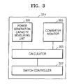
- FIG. 3 is a schematic block diagram illustrating an inner structure of a controller of FIG. 2 , according to an embodiment.
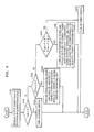
- FIG. 4 is a schematic flowchart illustrating a method of controlling a grid-connected energy storage system according to an embodiment
- Certain exemplary embodiments are described in detail with reference to the attached drawings. Like reference numerals generally designate like elements throughout the specification. In the description, the detailed descriptions of well-known functions and structures may be omitted so as not to hinder the understanding of various inventive aspects. Certain embodiments relate to a grid-connected energy storage system having high efficiency use of a converter and a method of controlling the system.
- FIG. 1 is a schematic block diagram illustrating a grid-connected energy storage system 100 according to an embodiment.
- the grid-connected energy storage system 100 (hereinafter, an energy storage system) is connected to a power generation system 130, a grid 140, and may supply power to a load 150.
- the power generation system 130 generates electrical energy with an energy source and outputs the electrical energy to the energy storage system 100.
- the power generation system 130 may be, for example, a solar power generation system, a wind power generation system, or a tidal power generation system, and or may be another renewable energy source, such as solar heat or geothermal heat.
- a solar cell generates electrical energy from sunlight and may be easily installed in a house or a factory, and thus may be appropriately used with the energy storage system 100, which may be installed in houses.
- the power generation system 130 includes a plurality of power generation modules 1 through n that are connected in parallel, and each power generation module generates electrical energy.
- the power generation system 130 is a large-capacity energy system.
- the grid 140 may include a power station, a substation, a power line, etc.
- the grid 140 can supply power to the energy storage system 100 and/or the load 150 and can receive power supplied from the energy storage system 100.
- the grid 140 is in an abnormal state, the grid 140 does not supply power to the energy storage system 100 or the load 150, and the energy storage system 100 does not supply power to the grid 140.
- the load 150 consumes power generated by the power generation system 130, power stored in a storage device 120, or power supplied by the grid 140.
- the load 150 may be, for example, a house or a factory.
- the energy storage system 100 may store power generated by the power generation system 130 in the storage device 120, send generated power to the grid 140, send power stored in the storage device 120 to the grid 140, and store power supplied by the grid 140 in the storage device 120.
- the energy storage system 100 may supply power to the load 150 during abnormal situations, for example, during a power outage in which the grid 140 is unable to supply power, by performing an uninterruptible power supply (UPS) operation.
- the energy storage system 100 may supply power generated from the power generation system 130 or power stored in the storage device 120 to the load 150, even when the grid 140 is in a normal state.
- UPS uninterruptible power supply
- the energy storage system 100 may include a converter 111, a bidirectional inverter 112, a bidirectional converter 113, a combined controller 114, a battery management system (BMS) 115, a direct current (DC) link unit 116, and a switching device 117.
- BMS battery management system
- DC direct current
- the converter 111 is connected between the power generation system 130 and a first node N1 and sends power generated from the power generation system 130 to the first node N1. Operation of the converter 111 may vary according to the type of the power generation system 130.
- the power generation system 130 is a wind power generation system or a tidal power generation system that outputs AC power
- the converter 111 converts the AC power of the power generation system 130 into DC power and outputs the DC power to the first node N1.
- the power generation system 130 is a solar cell that outputs DC power
- the converter 111 receives DC power from the power generation system 130 and supplies DC power to the first node N1.
- the converter 111 performs a maximum power point tracking (MPPT) control so as to obtain maximum power generated by a solar power generation system, a wind power generation system, or a tidal power generation system according to the combined controller 114.
- the converter 111 includes converters 1 through n respectively corresponding to the plurality of power generation modules 1 through n of the power generation system 130.
- the converters 1 through n may be selectively connected to the power generation modules 1 through n via the switching device 117.
- the switching device 117 may connect power generation modules to at least one converter simultaneously or one at a time.
- the DC link unit 116 may be connected between the first node N 1 and a bidirectional inverter 112 to maintain the DC voltage level of the first node N1 at a DC link level.
- the voltage level at the first node N1 may be unstable due to instantaneous voltage sagging of the power generation system 130 or the grid 140 or peak load generation in the load 150.
- the voltage at the first node N1 is preferably stable for normal operations of the bidirectional converter 113 and the bidirectional inverter 112.
- the DC link unit 116 may stabilize the DC voltage level at the first node N1, and the DC link unit 116 may include a capacitor.
- the capacitor may be an aluminum electrolytic capacitor, polymer capacitor or a high voltage and large current multi layer ceramic capacitor (MLCC).
- the DC link unit 116 is formed as an individual element, but the DC link unit 116 may be formed inside the bidirectional converter 113, the bidirectional inverter 112, or the converter 111.
- the bidirectional inverter 112 is a power converter connected between the first node N1 and the grid 140.
- the bidirectional inverter 112 rectifies an AC voltage from the grid 140 to generate DC power to be stored in the storage device 120.
- the bidirectional inverter 112 also converts a DC voltage from the power generation system 130 or the battery 120 into an AC voltage to be output to the grid 140.
- the bidirectional inverter 112 may also include a filter for removing certain frequency components from the AC voltage that is to be output to the grid 140, and may perform various other functions, such as limiting voltage changes, improving power factor, removing DC components, protecting against transient phenomena, etc.
- the bidirectional converter 113 is a power converter connected between the first node N 1 and the battery 120.
- the bidirectional converter 113 converts a DC link voltage at the first node N1 into a DC voltage to be stored in the battery 120 and converts a voltage stored in the battery 120 into a DC link voltage level to be transmitted to the first node N1.
- the bidirectional converter 113 may operate as a buck converter for adjusting the DC link voltage level of the first node N1 to a battery storage voltage.
- the bidirectional converter 113 may also operate as a boost converter for adjusting the battery storage voltage to the DC link voltage level at the first node N1.
- the battery 120 stores power supplied from the power generation system 130 or the grid 140.
- the battery 120 may be any of various types of battery cells.
- the battery 120 may be a nickel-cadmium battery, a lead storage battery, a nickel metal hydride battery (NiMH), a lithium ion battery, or a lithium polymer battery.
- NiMH nickel metal hydride battery
- the BMS (battery management system) 115 is connected to the battery 120 and controls charge and discharge operations of the battery 120 according to the combined controller 114. Discharge current and charge current are respectively transmitted from the battery 120 to the bidirectional converter 130 and from the bidirectional converter 130 to the battery 120 via the BMS 115.
- the BMS 115 may also includes various features, such as overcharge protection, overdischarge protection, overcurrent protection, overvoltage protection, overheat protection, cell balancing, etc., in order to protect the battery 120.
- the BMS 115 may monitor voltage, current, temperature, the amount of power remaining, the life span, etc., of the battery 120, and may send the information to the combined controller 114.
- the BMS 115 is separately formed from the battery 120, but the BMS 115 and the battery 120 may be integrated in a battery pack.
- the combined controller 114 receives information including voltage, current, temperature, etc., about the grid 140 from the grid 140. The combined controller 114 determines whether an abnormal situation has occurred in the grid 140 based on the information about the grid 140. When the grid 140 is in an abnormal state, the combined controller 114 outputs power stored in the battery 120 or power generated by the power generation system 130 to the load 150 and prevents power from being supplied from the energy storage system 100 to the grid 140.
- the combined controller 114 controls each component of the energy storage system 100 so as to supply power stored in the battery 120 to the grid 140.
- the energy storage system 100 supplies power stored in the battery 120 to the grid 140 so as to supply the power for free or to sell the power to the grid 140 management entity.
- the combined controller 114 transmits a pulse width modulated (PWM) control signal that controls a switching operation of each of the converter 111, the bidirectional inverter 112, and the bidirectional converter 113.
- PWM pulse width modulated
- the PWM control signal minimizes losses due to power conversions performed by the converter 111, the bidirectional inverter 112, and the bidirectional converter 113 through having a duty ratio optimally controlled according to an input voltage of each of the converter 111, the bidirectional inverter 112, and the bidirectional converter 113.
- the combined controller 114 receives signals corresponding to voltage, current, and temperature sensed at each input terminal of the converter 111, the bidirectional inverter 112, and the bidirectional converter 113 and sends a converter control signal and an inverter control signal on based on the sensing signals.
- the combined controller 114 measures output power of each of the power generation modules 1 through n of the power generation system 130 and selectively connects the power generation modules 1 through n to the converter 111. The operation of selectively connecting the converter 111 with respect to the combined controller 114 is described below.
- FIG. 2 is a more detailed view illustrating a switching device connecting a power generation system 230 of an energy storage system 200 with a converter 211, according to some embodiments.
- FIG. 3 is a schematic block diagram illustrating an inner structure of a controller 214 of FIG. 2 , according to some embodiments.
- an energy storage system 200 is connected to a solar power generation system 230, but embodiments of the present invention are not limited thereto, and thus the energy storage system 200 may be connected to another power generation system.
- the energy storage system 200 stores power generated by the solar power generation system 230 in a battery 220 and supplies the power to a grid 240 or a load 250.
- the solar power generation system 230 includes a plurality of solar cell modules 230a, 230b, and 230c, wherein the solar cell modules output DC current according to the amount of sunshine exposed thereto.
- the solar cell modules 230a, 230b, and 230c have different outputs according to the varying conditions thereof, such as solar radiation, temperature, and a drive operating point.
- Each of the solar cell modules 230a, 230b, and 230c may include a plurality of solar cells connected in series or in parallel in order to obtain a desired output. In the system of FIG. 2 , three solar cell modules are illustrated, but more solar cell modules may be formed according to installation location or design in order to obtain a desired amount of power.
- a converter 211 converts DC power that is output from the power generation system 230 into DC power at a desired voltage level.
- the converter 211 includes a plurality of converters 211a, 211b, and 211c connected in parallel and respectively corresponding to the solar cell modules 230a, 230b, and 230c. In FIG. 2 , three converters 211 are formed, but more or fewer converters 211 corresponding to the number of the power generation system 230 may be formed. Accordingly, power output by each of the solar cell modules 230a, 230b, and 230c may be individually and independently converted to increase power conversion efficiency of the converter 211.
- the converters 211 a, 211 b, and 211 c are controlled to selectively operate according to the amounts of power generated by the solar cell modules 230a, 230b, and 230c.
- each solar cell module may generate a different amount of power according to weather conditions for generating energy, installation location, and installation direction of the solar cell modules 230a, 230b, and 230c. In this case, when all the converters connected to the solar cell modules 230a, 230b, and 230c are operated, the efficiency of the converters is decreased.
- At least one converter is selectively operated from among the converters 211 a, 211 b, and 211 c according to the amounts of power generated by the solar cell modules 230a, 230b, and 230c in order to increase the efficiency of the converters.
- the converter 211 is controlled to follow the maximum output point according to the states of the solar cell modules 230a, 230b, and 230c.
- a bidirectional inverter 212 rectifies an AC voltage that is input from the grid 240 to a DC voltage to be stored in the battery 220 and outputs the DC voltage. Also, the bidirectional inverter 212 converts a DC voltage that is output from the power generation system 230 or the battery 220 into an AC voltage to be output to the grid 240 and outputs the AC voltage.
- a bidirectional converter 213 converts a DC voltage that is output from the power generation system 230 to a battery storage voltage and converts the battery storage voltage to a DC link voltage level to be supplied to the bidirectional converter 212.
- the battery 220 stores power supplied from the power generation system 230 or the grid 240.
- the battery 220 and a BMS may be integrated as a battery pack.
- a switch 217 includes series switches SWa, SWb, and SWc formed on lines connecting the solar cell modules 230a, 230b, and 230c with the converters 211a, 211b, and 211c in series, and parallel switches SW1, SW2, and SW3 for connecting the solar cell module 230a with the solar cell module 230b, the solar cell module 230b with the solar cell module 230c, and the solar cell module 230c with the solar cell module 230a, respectively.
- On-off operations of the series switches SWa, SWb, and SWc and the parallel switches SW1, SW2, and SW3 may be controlled according to an operation algorithm in the controller 214.
- the controller 214 controls the converter 211 according to the maximum output point. For this, the controller 214 measures the amount of power output by the solar cell modules 230a, 230b, and 230c and controls the converter 211 to operate in an operating mode in which the maximum output is generated according to an operation having various algorithms.
- the controller 214 connects the solar cell modules 230a, 230b, and 230c to the converters 211a, 211b, and 211c via the switch 217 (in such a way as to) optimize power generation efficiency.
- the controller 214 measures the amount of power generated by each of the solar cell modules 230a, 230b, and 230c, and prevents a connection between solar cell modules having low amounts of generated power and converters of the converter 211 via the switch 217.
- controller 214 connects the solar cell modules having the low amounts of generated power to the same converter in the converter 217, so that power input to the converter is increased, thereby increasing the efficiency of the converter and extending the life span of the converter.
- the controller 214 periodically monitors the condition of the converter so as to exclude a converter having defects, for example, a converter that has stopped functioning, thereby minimizing errors in the system operation.
- the controller 214 includes a power generation measuring unit 301, a converter monitor 303, a calculator 305, and a switch controller 307.
- the controller 214 may be integrated with the combined controller 114 or may be formed separately from the combined controller 114 in FIG. 1 .
- the power generation measuring unit 301 measures output power Pout of each of the solar cell modules 230a, 230b, and 230c.
- the output power Pout may be measured periodically or may be measured as desired by an operator depending on a situation.
- the converter monitor 203 may periodically monitor and warn about operation conditions and defects of the converters 211 a, 211 b, and 211 c.
- the converter monitor 203 compiles a database recording defects, replacement time, the number of operations, and operating hours of the converters 211 a, 211 b, and 211 c and periodically or aperiodically updates the database.
- the calculator 305 receives power output by each of the solar cell modules 230a, 230b, and 230c from the power generation measuring unit 301, and also receives information about the converters 211 a, 211b, and 211 c from the converter monitor 203.
- the calculator 305 compares the power output by each of the solar cell modules 230a, 230b, and 230c with a reference value based on the information.
- the switch controller 307 selects at least one converter based on the comparison performed by the calculator 305, and outputs a control signal to the switch 217 for turning on series switches and parallel switches corresponding to the selected converter in order to connect the solar cell modules 230a, 230b, and 230c to the at least one selected converter.
- the converter may be selected, for example, according to the operating hours of the converter, the number of operations of the converter, arrangement sequence of the converter, optional selection, etc.
- FIG. 4 is a schematic flowchart of a method of controlling an energy storage system according to some embodiments. The method of controlling the energy storage system is described with reference to FIGS. 3 and 4 .
- power generation measuring unit 301 measures power output by each of power generation modules, that is, an output power Pout.
- the output power Pout may be measured periodically, aperiodically, or as desired by an operator.
- calculator 305 compares the amount of power output by each of the solar cell modules 230a, 230b, and 230c with a first comparative value A.
- the first comparative value A may be a percentage of input power required for a converter to output maximum power, for example, 70 % of the required input power.
- the switch controller 307 turns on series switches connected to those power generation modules.
- the power generation modules having output power greater than the first comparative value A are, therefore, connected to corresponding converters via the series switches, and the connected converters convert power.
- the calculator 305 adds up the amount of power output by each of the remaining solar cell modules, which have output power less than the first comparative value A, and determines whether the sum is less than a second comparative value B.
- the second comparative value may be a percentage of the input power required for a converter to output maximum power.
- the second comparative value B may be a value greater than the first comparative value A, for example, 80 % of the required input power.
- the switch controller 307 selects a converter having a short operating time from among non-operating converters and connects the power generation modules to the selected converter (S440).
- the least used non-operating converter is selected.
- corresponding series and parallel switches are turned on.
- the meaning of the short operating time in S440 refers to selecting the least used converter among the converters because the embodiment of the present invention is selectively switching and using a plurality of converters, and then the operating time of the plurality of converters is different respectively, thereby efficiency of converter use is increased.
- the calculator 305 adds up the amounts of power output by two of the remaining solar cell modules and compares the sum with the second comparative value B.
- the calculator 305 compares a sum of the amount of power output by one power generation module P and the amount of power output by a previous power generation module P- or the amount of power output by a next power generation module P+ with the second comparative value B.
- the switch controller 307 connects the adjacent two power generation modules to a converter having a short operating time from among the non-operating converters. Therefore, the least used non-operating converter is selected. To connect each of the adjacent two power generation modules to the selected converter, corresponding series and parallel switches are turned on. When both of the sum of P and P- and the sum of P and P+ are less than the second comparative value B, the converter may select the modules of which the sum of the amounts of power is closer to the second comparative value B.
- the switch controller 307 connects each of the power generation modules to the corresponding converters. Then, series switches connected to each of the power generation module are turned on.
- the series switch SWa is turned on. Output powers P2 and P3 of the remaining solar cell modules 230b and 230c are added up.
- the solar cell modules 230b and 230c are connected to a converter having a short operating time from among the converters 211b and 211c, for example, the converter 211b. Accordingly, the series switch SWb and the parallel switch SW2 are turned on. If the sum P2+P3 of the solar cell modules 230b and 230c exceeds the second comparative value, the series switch SWb and the series switch SWc are turned on.
- the solar cell modules 230a, 230b, and 230c when all the amounts of power output by the solar cell modules 230a, 230b, and 230c are less than the first comparative value A, all the amounts of power output by the solar cell modules 230a, 230b, and 230c are added up.
- the solar cell modules 230a, 230b, and 230c are connected to a converter having a short operating time from among the converters 211 a, 211 b, and 211 c, for example, the convert 211 b. Accordingly, the series switch SWb and the parallel switches SW1 and SW2 are turned on.
- the solar cell modules 230a, 230b, and 230c are connected to the converter 211b having a short operating time from among the converters 211 a, 211 b, and 211 c. Accordingly, the series switch SWb and the parallel switch SW2 are turned on.
- the remaining solar cell module 230a may be connected to the converter 211a via the series switch SWa or may wait until power generation is next measured.
- the solar cell modules 230a, 230b, and 230c are connected to the converters 211a, 211b, and 211c via the switches SWa, SWb, and SWc, respectively.
- the modules of which the sum is closer to the second comparative value, that is the sum P1+P2 are selected, and the selected modules are connected to the converter 211b having a short operating time from among the converters 211 a and 211b. Accordingly, the series switch SWb and the parallel switch SW1 are turned on.
- a grid-connected energy storage system includes a plurality of power generation modules and a plurality of converters, so that the converters can be operated individually and independently.
- the grid-connected energy storage system includes a plurality of series switches connected between the power generation modules and the converters and a plurality of parallel switches connected between the power generation modules, so that the converters are selectively operated based on power generated by the power generation modules, thereby improving the efficiency of the converter.
Landscapes
- Engineering & Computer Science (AREA)
- Power Engineering (AREA)
- Business, Economics & Management (AREA)
- Emergency Management (AREA)
- Supply And Distribution Of Alternating Current (AREA)
- Charge And Discharge Circuits For Batteries Or The Like (AREA)
Applications Claiming Priority (1)
| Application Number | Priority Date | Filing Date | Title |
|---|---|---|---|
| KR1020090125030A KR101097260B1 (ko) | 2009-12-15 | 2009-12-15 | 계통 연계형 전력 저장 시스템 및 전력 저장 시스템 제어 방법 |
Publications (2)
| Publication Number | Publication Date |
|---|---|
| EP2337184A2 true EP2337184A2 (fr) | 2011-06-22 |
| EP2337184A3 EP2337184A3 (fr) | 2013-02-27 |
Family
ID=43829384
Family Applications (1)
| Application Number | Title | Priority Date | Filing Date |
|---|---|---|---|
| EP20100252115 Withdrawn EP2337184A3 (fr) | 2009-12-15 | 2010-12-15 | Système de stockage d'énergie raccordé au réseau et son procédé de commande |
Country Status (5)
| Country | Link |
|---|---|
| US (1) | US8716891B2 (fr) |
| EP (1) | EP2337184A3 (fr) |
| JP (1) | JP5155373B2 (fr) |
| KR (1) | KR101097260B1 (fr) |
| CN (1) | CN102097821B (fr) |
Cited By (29)
| Publication number | Priority date | Publication date | Assignee | Title |
|---|---|---|---|---|
| WO2012098392A1 (fr) * | 2011-01-18 | 2012-07-26 | Enecsys Limited | Systèmes solaires photovoltaïques |
| EP2518855A3 (fr) * | 2011-04-29 | 2013-10-16 | General Electric Company | Coordination de commutation de convertisseurs CC-CC distribués pour des centrales photovoltaïques hautement efficaces |
| WO2013174903A1 (fr) * | 2012-05-25 | 2013-11-28 | Sma Solar Technology Ag | Détermination de configuration de câble dans un inverseur multicâble |
| WO2014083083A1 (fr) * | 2012-11-29 | 2014-06-05 | Kostal Industrie Elektrik Gmbh | Dispositif électrique et installation électrique équipée d'un dispositif électrique |
| EP2770539A1 (fr) * | 2013-02-20 | 2014-08-27 | Total Marketing Services | Système de gestion électronique de cellules génératrices d'électricité, système de génération d'électricité et procédé de gestion électronique de flux d'énergie |
| WO2014033467A3 (fr) * | 2012-08-31 | 2014-09-04 | Off Grid Energy Ltd. | Module de puissance électrique mobile |
| CN104303392A (zh) * | 2012-05-22 | 2015-01-21 | 索尼公司 | 控制系统 |
| WO2014150283A3 (fr) * | 2013-03-15 | 2015-04-23 | Qualcomm Incorporated | Chargeur à phases multiples |
| CN104600730A (zh) * | 2015-01-21 | 2015-05-06 | 中国南方电网有限责任公司调峰调频发电公司 | 一种大容量储能系统中多储能变流器离网无线并列运行方法 |
| WO2015077534A1 (fr) * | 2013-11-22 | 2015-05-28 | Massachusetts Institute Of Technology | Équilibrage de puissance photovoltaïque et traitement de puissance différentielle |
| WO2015039998A3 (fr) * | 2013-09-17 | 2015-08-27 | Sma Solar Technology Ag | Circuit pour onduleur photovoltaïque permettant l'équilibrage d'une mise hors circuit au moyen d'interrupteurs de court-circuit, et utilisations du circuit |
| EP2797198A4 (fr) * | 2011-12-19 | 2015-09-02 | Panasonic Ip Man Co Ltd | Dispositif de charge et de décharge et système de charge et de décharge l'utilisant |
| EP2806524A4 (fr) * | 2012-01-20 | 2015-10-14 | Kyocera Corp | Système d'alimentation électrique et dispositif d'alimentation électrique |
| EP2843799A4 (fr) * | 2012-04-27 | 2015-11-25 | Panasonic Ip Man Co Ltd | Système de commutation de câblage |
| US9312699B2 (en) | 2012-10-11 | 2016-04-12 | Flexgen Power Systems, Inc. | Island grid power supply apparatus and methods using energy storage for transient stabilization |
| EP2976833A4 (fr) * | 2013-03-18 | 2017-01-11 | Cyboenergy, Inc. | Onduleurs de puissance lunaire intelligents et extensibles |
| US9553517B2 (en) | 2013-03-01 | 2017-01-24 | Fllexgen Power Systems, Inc. | Hybrid energy storage system and methods |
| EP3021446A4 (fr) * | 2013-07-08 | 2017-01-25 | Kyocera Corporation | Dispositif de conversion de puissance, système de conversion de puissance, et procédé de conversion de puissance |
| EP3301800A1 (fr) * | 2016-09-30 | 2018-04-04 | ABB Schweiz AG | Système de convertisseur de puissance pour une connexion à un réseau de distribution d'énergie électrique |
| US10289080B2 (en) | 2012-10-11 | 2019-05-14 | Flexgen Power Systems, Inc. | Multi-generator applications using variable speed and solid state generators for efficiency and frequency stabilization |
| DE102017223392A1 (de) * | 2017-12-20 | 2019-06-27 | Siemens Aktiengesellschaft | System zur Speicherung elektrischer Energie sowie Schaltungsanordnung für ein System zur Speicherung elektrischer Energie |
| WO2019229297A1 (fr) * | 2018-05-29 | 2019-12-05 | L7 Drive Oy | Convertisseur cc-cc adaptatif s'utilisant avec une charge et un chargeur |
| US10574055B2 (en) | 2014-12-30 | 2020-02-25 | Flexgen Power Systems, Inc. | Transient power stabilization device with active and reactive power control |
| DE102018127132A1 (de) * | 2018-10-30 | 2020-04-30 | Sma Solar Technology Ag | Wechselrichter mit mindestens zwei Gleichspannungswandlern und Verwendung eines solchen Wechselrichters in einer Photovoltaikanlage |
| DE102018127130A1 (de) * | 2018-10-30 | 2020-04-30 | Sma Solar Technology Ag | Wechselrichter mit mindestens zwei Gleichspannungswandlern |
| EP3651306A4 (fr) * | 2017-07-03 | 2020-06-10 | Power Electronics España, S.L. | Système d'alimentation intrinsèque pour services auxiliaires de convertisseurs de puissance |
| EP3748469A1 (fr) * | 2014-06-23 | 2020-12-09 | Gridbridge, Inc. | Gestionnaire et routeur d'énergie de bord de réseau de distribution électrique hautement flexible |
| CN113078710A (zh) * | 2021-04-01 | 2021-07-06 | 广东电网有限责任公司广州供电局 | 一种蓄电池组充放电管理装置 |
| EP3996027A1 (fr) | 2020-11-06 | 2022-05-11 | ABB Schweiz AG | Procédé et système de surveillance et / ou de fonctionnement d'un actif de système d'alimentation |
Families Citing this family (120)
| Publication number | Priority date | Publication date | Assignee | Title |
|---|---|---|---|---|
| US11735910B2 (en) | 2006-12-06 | 2023-08-22 | Solaredge Technologies Ltd. | Distributed power system using direct current power sources |
| US11687112B2 (en) | 2006-12-06 | 2023-06-27 | Solaredge Technologies Ltd. | Distributed power harvesting systems using DC power sources |
| US8013472B2 (en) | 2006-12-06 | 2011-09-06 | Solaredge, Ltd. | Method for distributed power harvesting using DC power sources |
| US8319471B2 (en) | 2006-12-06 | 2012-11-27 | Solaredge, Ltd. | Battery power delivery module |
| US11888387B2 (en) | 2006-12-06 | 2024-01-30 | Solaredge Technologies Ltd. | Safety mechanisms, wake up and shutdown methods in distributed power installations |
| US8947194B2 (en) | 2009-05-26 | 2015-02-03 | Solaredge Technologies Ltd. | Theft detection and prevention in a power generation system |
| US11855231B2 (en) | 2006-12-06 | 2023-12-26 | Solaredge Technologies Ltd. | Distributed power harvesting systems using DC power sources |
| EP2237403A1 (fr) * | 2009-03-30 | 2010-10-06 | SMA Solar Technology AG | Onduleur avec deux ponts asymmetrics et une branche à roue libre découplante l'entrée du courant continu de la sortie du courant alternatif |
| EP2415146A1 (fr) | 2009-04-01 | 2012-02-08 | Nextronex Inc. | Système solaire raccordé au réseau et procédé |
| KR101094002B1 (ko) * | 2009-12-16 | 2011-12-15 | 삼성에스디아이 주식회사 | 전원 변환 장치 |
| KR101156535B1 (ko) * | 2010-01-18 | 2012-06-21 | 삼성에스디아이 주식회사 | 전력 저장 장치와 그 동작 방법 및 전력 저장 시스템 |
| DE102010017746A1 (de) * | 2010-05-03 | 2011-11-03 | Sma Solar Technology Ag | Verfahren zur Begrenzung der Generatorspannung einer photovoltaischen Anlage im Gefahrenfall und photovoltaische Anlage |
| JP5601912B2 (ja) * | 2010-07-09 | 2014-10-08 | 株式会社ダイヘン | 電力変換装置の制御装置、および、この制御装置を用いた系統連系インバータシステム |
| EP2528184B1 (fr) * | 2011-05-25 | 2014-09-10 | Siemens Aktiengesellschaft | Procédé et appareil de contrôle d'une liaison de transmission CC |
| JP2012252580A (ja) * | 2011-06-03 | 2012-12-20 | Sony Corp | 電力制御装置、電力管理装置および電力管理システム |
| US9252631B2 (en) * | 2011-06-08 | 2016-02-02 | Andrew V. Latham | Data center battery enhancement method and system |
| US9059604B2 (en) * | 2011-06-27 | 2015-06-16 | Sunpower Corporation | Methods and apparatus for controlling operation of photovoltaic power plants |
| KR101300354B1 (ko) * | 2011-06-29 | 2013-08-28 | 전남대학교산학협력단 | 계통 연계형 전력변환장치 |
| CN102222965A (zh) * | 2011-06-29 | 2011-10-19 | 黄俊嘉 | 混合动力的不间断电源 |
| CN102255519A (zh) * | 2011-06-29 | 2011-11-23 | 黄俊嘉 | 节能电源配电装置 |
| CN102255356B (zh) * | 2011-06-29 | 2014-02-05 | 黄俊嘉 | 高效率的不间断电源 |
| JP5777965B2 (ja) * | 2011-07-22 | 2015-09-16 | 京セラ株式会社 | 故障診断方法、系統連系装置、及び制御装置 |
| JP5719714B2 (ja) * | 2011-07-22 | 2015-05-20 | 京セラ株式会社 | 起動制御方法、系統連系装置、及び制御装置 |
| JP5960958B2 (ja) | 2011-07-27 | 2016-08-02 | 京セラ株式会社 | 電力管理システム |
| JP5854687B2 (ja) * | 2011-08-03 | 2016-02-09 | 株式会社東芝 | 太陽光発電システム |
| CN102280940A (zh) * | 2011-09-06 | 2011-12-14 | 天宝电子(惠州)有限公司 | 新能源分布式储能应用控制系统 |
| CN103001307A (zh) * | 2011-09-15 | 2013-03-27 | 旭隼科技股份有限公司 | 一种再生能源供电系统及其供电方法 |
| JP5845408B2 (ja) * | 2011-09-26 | 2016-01-20 | パナソニックIpマネジメント株式会社 | 太陽光発電の給電システム |
| US9136732B2 (en) * | 2011-10-15 | 2015-09-15 | James F Wolter | Distributed energy storage and power quality control in photovoltaic arrays |
| EP2587334A1 (fr) * | 2011-10-24 | 2013-05-01 | Imec | Configuration PV reconfigurable |
| KR101868350B1 (ko) * | 2011-10-26 | 2018-06-19 | 엘지전자 주식회사 | 태양광발전장치 및 이의 운전방법 |
| US20130127257A1 (en) * | 2011-11-22 | 2013-05-23 | Panasonic Corporation | Power generating system and wireless power transmission system |
| CN102522919A (zh) * | 2011-12-08 | 2012-06-27 | 常州天合光能有限公司 | 智能光伏组件及其控制方法 |
| CN102427315A (zh) * | 2011-12-19 | 2012-04-25 | 浙江大学 | 基于直流母线的光伏发电装置 |
| TW201328118A (zh) * | 2011-12-28 | 2013-07-01 | Hon Hai Prec Ind Co Ltd | 不間斷電源系統 |
| GB2498365A (en) | 2012-01-11 | 2013-07-17 | Solaredge Technologies Ltd | Photovoltaic module |
| GB2498790A (en) | 2012-01-30 | 2013-07-31 | Solaredge Technologies Ltd | Maximising power in a photovoltaic distributed power system |
| WO2013135777A2 (fr) * | 2012-03-14 | 2013-09-19 | Belenos Clean Power Holding Ag | Unite a energie renouvelable a connectique simplifie |
| US10203735B2 (en) * | 2012-03-21 | 2019-02-12 | Bloom Energy Corporation | Systems and methods for providing fuel cell power to a data center |
| CN102624028A (zh) * | 2012-03-28 | 2012-08-01 | 南京大学 | 基于太阳能电池板接入方式选择器的光伏并网发电系统 |
| CN102624288A (zh) * | 2012-04-09 | 2012-08-01 | 友达光电股份有限公司 | 交流太阳能模块及电能调度方法 |
| KR101942095B1 (ko) * | 2012-04-17 | 2019-01-25 | 한국전자통신연구원 | 에너지 하베스팅 시스템에서의 전력 변환 장치 및 그 방법 |
| KR101390641B1 (ko) * | 2012-05-07 | 2014-04-30 | 한국에너지기술연구원 | 전력변환 시스템 및 전력변환 방법과, 그 시스템을 제어하는 장치 및 방법 |
| JP5983026B2 (ja) * | 2012-05-22 | 2016-08-31 | ソニー株式会社 | 制御システム |
| US9608438B2 (en) | 2012-07-17 | 2017-03-28 | Electronics And Telecommunications Research Institute | Inverter system for photovoltaic power generation |
| DE102012212654A1 (de) | 2012-07-19 | 2014-01-23 | Robert Bosch Gmbh | Energiespeicher für Photovoltaikanalage, Energiespeicherkraftwerk, Steuereinrichtung und Verfahren zum Betreiben eines Energiespeichers |
| KR101347437B1 (ko) | 2012-09-18 | 2014-01-03 | (주)에스엔디파워닉스 | 부하 추종 운전 기능을 가진 전력 제어 시스템 및 그 전력 제어 방법 |
| JP6080290B2 (ja) * | 2012-09-27 | 2017-02-15 | ホーチキ株式会社 | 太陽光発電システム |
| EP2717409A1 (fr) * | 2012-10-03 | 2014-04-09 | Belenos Clean Power Holding AG | Régulation d'un module électronique adaptateur de tension |
| US9671810B2 (en) * | 2012-10-26 | 2017-06-06 | International Business Machines Corporation | Energy efficient solar powered high voltage direct current based data center |
| KR101632353B1 (ko) * | 2012-11-13 | 2016-06-21 | 주식회사 엘지화학 | 이차전지의 충전 및 방전 제어 장치 및 방법 |
| US9727929B2 (en) * | 2012-11-21 | 2017-08-08 | Kabushiki Kaisha Toshiba | Energy management system, energy management method, program, server apparatus, and local server |
| JP6191403B2 (ja) * | 2013-01-24 | 2017-09-06 | オムロン株式会社 | パワーコンディショナ、太陽電池システム、および異常判定方法 |
| CN103280825B (zh) * | 2013-01-30 | 2016-01-06 | 东南大学 | 一种光伏电站多台逆变器协调控制装置及控制方法 |
| US10374447B2 (en) * | 2013-03-14 | 2019-08-06 | Infineon Technologies Austria Ag | Power converter circuit including at least one battery |
| US9548619B2 (en) * | 2013-03-14 | 2017-01-17 | Solaredge Technologies Ltd. | Method and apparatus for storing and depleting energy |
| JP5880778B2 (ja) * | 2013-03-20 | 2016-03-09 | 富士電機株式会社 | 太陽光発電システム |
| JP5842860B2 (ja) * | 2013-04-25 | 2016-01-13 | 株式会社安川電機 | 系統連系装置 |
| KR101298021B1 (ko) * | 2013-05-20 | 2013-08-26 | (주)가람이앤씨 | 고효율 태양광 발전장치 |
| ITMO20130146A1 (it) * | 2013-05-24 | 2014-11-25 | Une Srl | Sistema integrato di conservazione dell'energia elettrica da fonte rinnovabile in batterie ecologiche passive |
| KR101296829B1 (ko) * | 2013-06-05 | 2013-08-14 | 주식회사 에스엠씨코퍼레이션 | 태양광 발전 시스템 및 그 제어방법 |
| JP6267052B2 (ja) * | 2013-09-27 | 2018-01-24 | ルネサスエレクトロニクス株式会社 | 電源回路、及び電源回路の制御方法 |
| JP6425795B2 (ja) * | 2013-09-27 | 2018-11-21 | ルネサスエレクトロニクス株式会社 | 電源回路の制御方法 |
| KR101400123B1 (ko) * | 2013-10-14 | 2014-05-28 | 국방과학연구소 | 휴대용 발전기를 이용한 대용량 배터리 충전용 집전장치 |
| JP2015089320A (ja) * | 2013-11-01 | 2015-05-07 | ソニー株式会社 | 蓄電システムおよびその制御方法 |
| DE102013222641A1 (de) * | 2013-11-07 | 2015-05-07 | Bayerische Motoren Werke Aktiengesellschaft | Energiespeichersystem für ein elektrisch angetriebenes Fahrzeug |
| JP6020480B2 (ja) * | 2014-02-04 | 2016-11-02 | コニカミノルタ株式会社 | 電力制御装置、および画像形成装置 |
| KR101457094B1 (ko) * | 2014-02-07 | 2014-11-04 | 주식회사 아두봇 | 풍력 및 태양광을 이용한 하이브리드 발전 시스템 |
| CN104037877B (zh) * | 2014-06-12 | 2016-08-24 | 北方民族大学 | 一种家庭微网的自清洁太阳能供电系统及其太阳能电池的制备方法 |
| WO2015200931A1 (fr) | 2014-06-23 | 2015-12-30 | Gridbridge, Inc. | Routeur d'énergie de site polyvalent |
| DE102014109092A1 (de) * | 2014-06-27 | 2015-12-31 | Thyssenkrupp Ag | Antriebssystem für ein U-Boot |
| US20160079872A1 (en) * | 2014-09-12 | 2016-03-17 | Samsung Electro-Mechanics Co., Ltd. | Power converter |
| CN105490320B (zh) * | 2014-09-19 | 2018-12-21 | 比亚迪股份有限公司 | 光伏电站储能方法和系统 |
| KR101982123B1 (ko) * | 2014-12-19 | 2019-08-29 | 한국전기연구원 | 양극성 직류배전시스템에서의 상호보완적인 전력 제어 시스템 및 그 방법 |
| KR102308628B1 (ko) * | 2015-01-21 | 2021-10-05 | 삼성에스디아이 주식회사 | 하이브리드 전력변환 시스템 및 이를 이용하는 최대 효율 결정 방법 |
| US9780567B2 (en) | 2015-02-19 | 2017-10-03 | Cummins Power Generation Ip, Inc. | Energy storage system |
| US9812866B2 (en) | 2015-02-19 | 2017-11-07 | Cummins Power Generation Ip, Inc. | Energy storage system |
| DE102015204561A1 (de) * | 2015-03-13 | 2016-09-15 | Siemens Aktiengesellschaft | Verfahren zum Betrieb einer Wechselrichtervorrichtung und Wechselrichtervorrichtung |
| NO20150349A1 (en) * | 2015-03-20 | 2016-08-22 | Kongsberg Maritime As | Dynamic hybrid control |
| CN104993511A (zh) * | 2015-06-06 | 2015-10-21 | 苏州爱康低碳技术研究院有限公司 | 多功能智能户用光伏发电控制系统 |
| CN104967142A (zh) * | 2015-06-06 | 2015-10-07 | 苏州爱康低碳技术研究院有限公司 | 新型逆变器 |
| CN107431361B (zh) * | 2015-07-02 | 2019-05-07 | 戴纳动力有限责任公司 | 孤岛运行多个并网的功率转换器 |
| US10263430B2 (en) | 2015-08-14 | 2019-04-16 | Solarcity Corporation | Multi-phase inverter power control systems in an energy generation system |
| JP2017041919A (ja) * | 2015-08-17 | 2017-02-23 | 三菱電機株式会社 | 電力変換システム |
| EP3142153B1 (fr) * | 2015-09-12 | 2020-04-01 | IMEC vzw | Module photovoltaïque reconfigurable |
| KR102634859B1 (ko) * | 2015-11-06 | 2024-02-08 | 엘지전자 주식회사 | 전력 합산기, 전력 제어 장치 및 전력 소비 장치 |
| US9559521B1 (en) * | 2015-12-09 | 2017-01-31 | King Electric Vehicles Inc. | Renewable energy system with integrated home power |
| JP2017175725A (ja) * | 2016-03-22 | 2017-09-28 | 株式会社デンソー | 電力供給システム |
| WO2017171182A1 (fr) | 2016-03-30 | 2017-10-05 | 두산중공업 주식회사 | Dispositif d'attaque de convertisseurs et dispositif de commande de convertisseurs dans un système de génération d'énergie éolienne et dispositif d'attaque de modules d'éléments de commutation et dispositif de commande de modules d'éléments de commutation dans un système de génération d'énergie éolienne |
| US11177663B2 (en) | 2016-04-05 | 2021-11-16 | Solaredge Technologies Ltd. | Chain of power devices |
| KR101898587B1 (ko) * | 2016-05-04 | 2018-09-13 | 엘지전자 주식회사 | 태양광 모듈, 및 이를 구비하는 태양광 시스템 |
| CN106093803B (zh) * | 2016-06-07 | 2019-06-11 | 东莞市冠佳电子设备有限公司 | 开关电源老化测试电路 |
| CN106329926B (zh) * | 2016-10-08 | 2018-12-07 | 中国科学院光电研究院 | 一种适用于平流层浮空器用分布式高功率密度电源变换装置 |
| US11309714B2 (en) * | 2016-11-02 | 2022-04-19 | Tesla, Inc. | Micro-batteries for energy generation systems |
| JP6974913B2 (ja) | 2016-11-30 | 2021-12-01 | 株式会社辰巳菱機 | 負荷試験システム |
| KR102197177B1 (ko) * | 2017-01-19 | 2020-12-31 | 엘에스일렉트릭(주) | 에너지 저장 장치 및 이를 포함하는 에너지 저장 시스템 |
| US20170201170A1 (en) * | 2017-03-26 | 2017-07-13 | Ahmed Fayez Abu-Hajar | Method for generating highly efficient harmonics free dc to ac inverters |
| KR102308376B1 (ko) * | 2017-04-04 | 2021-10-01 | 엘에스일렉트릭(주) | 전력 전송 경로 제어가 가능한 태양광 발전 시스템 |
| KR20180122254A (ko) * | 2017-05-02 | 2018-11-12 | 한국전자통신연구원 | 전력 변환 장치 및 방법 |
| KR101940069B1 (ko) * | 2017-06-29 | 2019-01-18 | (주)삼우티이씨 | 태양광 전동유도발전기의 병렬운전 제어장치 |
| WO2019058821A1 (fr) * | 2017-09-22 | 2019-03-28 | 株式会社村田製作所 | Appareil de stockage d'énergie |
| CN107612035A (zh) * | 2017-10-24 | 2018-01-19 | 武汉大学 | 一种基于添加联络开关结构的提高光伏发电汇集系统轻载效率的方法 |
| KR102031306B1 (ko) * | 2017-12-11 | 2019-10-11 | 주식회사 이노썬 | 태양광 접속반 dc 입력 전원의 환산 제어장치 |
| WO2019145997A1 (fr) * | 2018-01-23 | 2019-08-01 | Tdk株式会社 | Système d'alimentation en courant continu |
| IT201800003474A1 (it) * | 2018-03-13 | 2019-09-13 | Future Light S R L | Sistema di accumulo perfezionato. |
| KR102488002B1 (ko) | 2018-04-05 | 2023-01-13 | 한국전자통신연구원 | 전력 변환 시스템 및 그것의 동작 방법 |
| KR102178447B1 (ko) * | 2018-12-13 | 2020-11-13 | 주식회사 포스코 | 무정전 전력 공급 마이크로그리드 시스템 |
| EP3893380A4 (fr) * | 2018-12-29 | 2021-11-24 | Huawei Technologies Co., Ltd. | Onduleur |
| KR102370792B1 (ko) * | 2019-02-15 | 2022-03-07 | 고려대학교 산학협력단 | 고효율 에너지 하베스팅을 위한 효율 인식 협동 다중 충전기술을 적용한 충전장치 |
| WO2021002539A1 (fr) * | 2019-07-03 | 2021-01-07 | 주식회사 네모엘텍 | Système de commutation série-parallèle de module solaire pour optimiser une tension de fonctionnement mppt sur la base d'un apprentissage automatique |
| EP3832874A1 (fr) * | 2019-12-03 | 2021-06-09 | ABB Schweiz AG | Ensemble de convertisseur |
| KR102112726B1 (ko) * | 2019-12-17 | 2020-05-19 | 표구옥 | 스마트 기기와 통신되는 태양광 충전 시스템을 사용한 개별 배터리 셀 충전 시스템 |
| CN111277033A (zh) * | 2020-03-04 | 2020-06-12 | 上海钧正网络科技有限公司 | 发电模块、发电装置和控制方法 |
| US11888342B2 (en) * | 2020-05-12 | 2024-01-30 | Monolithic Power Systems, Inc. | Bi-directional battery charging circuit with voltage regulation control |
| US11569668B2 (en) * | 2020-07-14 | 2023-01-31 | Igrenenergi, Inc. | System and method for dynamic balancing power in a battery pack |
| US20220115940A1 (en) * | 2020-10-10 | 2022-04-14 | The Regents Of The University Of Michigan | Power processing and energy storage |
| CN116941158A (zh) * | 2021-03-26 | 2023-10-24 | 华为数字能源技术有限公司 | 储能系统及其控制方法 |
| KR102439044B1 (ko) | 2021-08-11 | 2022-09-01 | (주)제이케이알에스티 | 광변색 내성 및 방열성 분체도료를 이용한 방제기능과 지진충격 감쇄용 면진 기능 및 충방전 기능을 구비한 에너지 저장 장치 |
| KR102525107B1 (ko) * | 2021-10-12 | 2023-04-25 | (주)미섬시스텍 | 연료전지 분산발전 전력 통제 모니터링 시스템 |
| KR102436399B1 (ko) * | 2022-02-10 | 2022-08-25 | (주)엔지피 | 에너지 저장 기능을 갖는 태양광발전 제어 시스템 |
Family Cites Families (21)
| Publication number | Priority date | Publication date | Assignee | Title |
|---|---|---|---|---|
| US5235232A (en) * | 1989-03-03 | 1993-08-10 | E. F. Johnson Company | Adjustable-output electrical energy source using light-emitting polymer |
| JP3254839B2 (ja) | 1993-08-27 | 2002-02-12 | 富士電機株式会社 | 系統連系用インバータの並列運転制御方法 |
| JP2000112545A (ja) * | 1998-09-30 | 2000-04-21 | Daihen Corp | 太陽光発電システム |
| JP3809316B2 (ja) * | 1999-01-28 | 2006-08-16 | キヤノン株式会社 | 太陽光発電装置 |
| JP2001016859A (ja) * | 1999-06-29 | 2001-01-19 | Nissin Electric Co Ltd | 電力変換装置 |
| JP2001268800A (ja) * | 2000-03-16 | 2001-09-28 | Kawasaki Steel Corp | 太陽光発電制御方法及び装置 |
| JP3656531B2 (ja) * | 2000-08-31 | 2005-06-08 | 松下電工株式会社 | 太陽光発電システム |
| JP2004319812A (ja) | 2003-04-17 | 2004-11-11 | Canon Inc | 電力変換器付き太陽電池モジュール |
| JP2005151662A (ja) | 2003-11-13 | 2005-06-09 | Sharp Corp | インバータ装置および分散電源システム |
| US7763797B2 (en) * | 2004-03-22 | 2010-07-27 | Pakedge Device & Software Inc. | Ceiling-mounted wireless network access point |
| EP1766490A4 (fr) * | 2004-07-13 | 2007-12-05 | Univ Central Queensland | Dispositif permettant de detecter une puissance maximum distribuee destine a des panneaux solaires |
| CN1945920B (zh) * | 2005-09-27 | 2012-09-05 | 歌美飒创新技术公司 | 变换器系统的操作方法 |
| JP4776348B2 (ja) * | 2005-11-11 | 2011-09-21 | シャープ株式会社 | インバータ装置 |
| WO2007125867A1 (fr) * | 2006-04-24 | 2007-11-08 | Sharp Kabushiki Kaisha | Systeme de generation d'energie photovoltaique et procede de commande de systeme de generation d'energie photovoltaique |
| KR20070009497A (ko) | 2006-11-28 | 2007-01-18 | (주) 다쓰테크 | 절연형 직류발전 모듈이 구성된 태양광 발전장치 및 그태양광 발전장치가 구비된 태양광 발전 관리시스템 |
| WO2008064605A1 (fr) | 2006-11-30 | 2008-06-05 | Beijing Hi-Tech Wealth Investment & Development Co., Ltd | Procédé, appareil et système permettant de fournir de l'énergie à l'aide de cellules photovoltaïques |
| DE502008001253D1 (de) * | 2008-02-27 | 2010-10-14 | Abb Schweiz Ag | Energiesystem umfassend eine Wind- oder Wasserkraftturbine |
| US7952232B2 (en) * | 2008-03-13 | 2011-05-31 | General Electric Company | Wind turbine energy storage and frequency control |
| US7800247B2 (en) * | 2008-05-30 | 2010-09-21 | Chun-Chieh Chang | Storage system that maximizes the utilization of renewable energy |
| US8106537B2 (en) * | 2008-07-01 | 2012-01-31 | Satcon Technology Corporation | Photovoltaic DC/DC micro-converter |
| ES2338088B8 (es) * | 2008-10-30 | 2011-08-04 | Asea Brown Boveri, S.A | Sistema y metodo de optimizacion de energia en generadores fotovoltaicos. |
-
2009
- 2009-12-15 KR KR1020090125030A patent/KR101097260B1/ko active IP Right Grant
-
2010
- 2010-10-21 JP JP2010236550A patent/JP5155373B2/ja active Active
- 2010-11-30 CN CN201010569879.3A patent/CN102097821B/zh active Active
- 2010-12-14 US US12/968,060 patent/US8716891B2/en active Active
- 2010-12-15 EP EP20100252115 patent/EP2337184A3/fr not_active Withdrawn
Non-Patent Citations (1)
| Title |
|---|
| None |
Cited By (45)
| Publication number | Priority date | Publication date | Assignee | Title |
|---|---|---|---|---|
| US10418818B2 (en) | 2011-01-18 | 2019-09-17 | Tesla, Inc. | Solar photovoltaic systems |
| US9276409B2 (en) | 2011-01-18 | 2016-03-01 | Solarcity Corporation | Solar photovoltaic systems |
| WO2012098392A1 (fr) * | 2011-01-18 | 2012-07-26 | Enecsys Limited | Systèmes solaires photovoltaïques |
| US8829715B2 (en) | 2011-04-29 | 2014-09-09 | General Electric Company | Switching coordination of distributed dc-dc converters for highly efficient photovoltaic power plants |
| EP2518855A3 (fr) * | 2011-04-29 | 2013-10-16 | General Electric Company | Coordination de commutation de convertisseurs CC-CC distribués pour des centrales photovoltaïques hautement efficaces |
| EP2797198A4 (fr) * | 2011-12-19 | 2015-09-02 | Panasonic Ip Man Co Ltd | Dispositif de charge et de décharge et système de charge et de décharge l'utilisant |
| EP2806524A4 (fr) * | 2012-01-20 | 2015-10-14 | Kyocera Corp | Système d'alimentation électrique et dispositif d'alimentation électrique |
| US10158226B2 (en) | 2012-04-27 | 2018-12-18 | Panasonic Intellectual Property Management Co., Ltd. | Line switching system |
| EP2843799A4 (fr) * | 2012-04-27 | 2015-11-25 | Panasonic Ip Man Co Ltd | Système de commutation de câblage |
| EP2854255A4 (fr) * | 2012-05-22 | 2016-03-09 | Sony Corp | Système de commande |
| CN104303392A (zh) * | 2012-05-22 | 2015-01-21 | 索尼公司 | 控制系统 |
| US9722425B2 (en) | 2012-05-25 | 2017-08-01 | Sma Solar Technology Ag | Determining a string configuration in a multistring-inverter |
| WO2013174903A1 (fr) * | 2012-05-25 | 2013-11-28 | Sma Solar Technology Ag | Détermination de configuration de câble dans un inverseur multicâble |
| WO2014033467A3 (fr) * | 2012-08-31 | 2014-09-04 | Off Grid Energy Ltd. | Module de puissance électrique mobile |
| US10289080B2 (en) | 2012-10-11 | 2019-05-14 | Flexgen Power Systems, Inc. | Multi-generator applications using variable speed and solid state generators for efficiency and frequency stabilization |
| US10615597B2 (en) | 2012-10-11 | 2020-04-07 | Flexgen Power Systems, Inc. | Grid power supply apparatus and methods using energy storage for transient stabilization |
| US9312699B2 (en) | 2012-10-11 | 2016-04-12 | Flexgen Power Systems, Inc. | Island grid power supply apparatus and methods using energy storage for transient stabilization |
| WO2014083083A1 (fr) * | 2012-11-29 | 2014-06-05 | Kostal Industrie Elektrik Gmbh | Dispositif électrique et installation électrique équipée d'un dispositif électrique |
| CN105264671B (zh) * | 2013-02-20 | 2017-10-24 | 道达尔销售服务公司 | 用于发电电池的电子管理系统、发电系统和用于电子地管理能量流的方法 |
| US9627893B2 (en) | 2013-02-20 | 2017-04-18 | Total Marketing Services | Electronic management system for electricity generating cells, electricity generating system and method for electronically managing energy flow |
| CN105264671A (zh) * | 2013-02-20 | 2016-01-20 | 道达尔销售服务公司 | 用于发电电池的电子管理系统、发电系统和用于电子地管理能量流的方法 |
| EP2770539A1 (fr) * | 2013-02-20 | 2014-08-27 | Total Marketing Services | Système de gestion électronique de cellules génératrices d'électricité, système de génération d'électricité et procédé de gestion électronique de flux d'énergie |
| WO2014128202A1 (fr) * | 2013-02-20 | 2014-08-28 | Total Marketing Services | Système de gestion électronique pour cellules de génération d'électricité, système de génération d'électricité et procédé de gestion électronique d'un flux d'énergie |
| US9553517B2 (en) | 2013-03-01 | 2017-01-24 | Fllexgen Power Systems, Inc. | Hybrid energy storage system and methods |
| US9219369B2 (en) | 2013-03-15 | 2015-12-22 | Qualcomm Incorporated | Multiphase charger |
| WO2014150283A3 (fr) * | 2013-03-15 | 2015-04-23 | Qualcomm Incorporated | Chargeur à phases multiples |
| EP2976833A4 (fr) * | 2013-03-18 | 2017-01-11 | Cyboenergy, Inc. | Onduleurs de puissance lunaire intelligents et extensibles |
| EP3021446A4 (fr) * | 2013-07-08 | 2017-01-25 | Kyocera Corporation | Dispositif de conversion de puissance, système de conversion de puissance, et procédé de conversion de puissance |
| US10298017B2 (en) | 2013-09-17 | 2019-05-21 | Sma Solar Technology Ag | Circuit arrangement for a photovoltaic inverter for break relief using short-circuit switches, and uses of the circuit arrangement |
| WO2015039998A3 (fr) * | 2013-09-17 | 2015-08-27 | Sma Solar Technology Ag | Circuit pour onduleur photovoltaïque permettant l'équilibrage d'une mise hors circuit au moyen d'interrupteurs de court-circuit, et utilisations du circuit |
| WO2015077534A1 (fr) * | 2013-11-22 | 2015-05-28 | Massachusetts Institute Of Technology | Équilibrage de puissance photovoltaïque et traitement de puissance différentielle |
| EP3748469A1 (fr) * | 2014-06-23 | 2020-12-09 | Gridbridge, Inc. | Gestionnaire et routeur d'énergie de bord de réseau de distribution électrique hautement flexible |
| US10574055B2 (en) | 2014-12-30 | 2020-02-25 | Flexgen Power Systems, Inc. | Transient power stabilization device with active and reactive power control |
| CN104600730A (zh) * | 2015-01-21 | 2015-05-06 | 中国南方电网有限责任公司调峰调频发电公司 | 一种大容量储能系统中多储能变流器离网无线并列运行方法 |
| EP3301800A1 (fr) * | 2016-09-30 | 2018-04-04 | ABB Schweiz AG | Système de convertisseur de puissance pour une connexion à un réseau de distribution d'énergie électrique |
| US11070079B2 (en) | 2017-07-03 | 2021-07-20 | Power Electronics España, S.L. | Integrated power supply system for auxiliary services for power converters |
| EP3651306A4 (fr) * | 2017-07-03 | 2020-06-10 | Power Electronics España, S.L. | Système d'alimentation intrinsèque pour services auxiliaires de convertisseurs de puissance |
| DE102017223392A1 (de) * | 2017-12-20 | 2019-06-27 | Siemens Aktiengesellschaft | System zur Speicherung elektrischer Energie sowie Schaltungsanordnung für ein System zur Speicherung elektrischer Energie |
| WO2019229297A1 (fr) * | 2018-05-29 | 2019-12-05 | L7 Drive Oy | Convertisseur cc-cc adaptatif s'utilisant avec une charge et un chargeur |
| US11476764B2 (en) | 2018-05-29 | 2022-10-18 | L7 Drive Oy | Adaptive DC to DC converter for use with a load and charger |
| DE102018127130A1 (de) * | 2018-10-30 | 2020-04-30 | Sma Solar Technology Ag | Wechselrichter mit mindestens zwei Gleichspannungswandlern |
| DE102018127132A1 (de) * | 2018-10-30 | 2020-04-30 | Sma Solar Technology Ag | Wechselrichter mit mindestens zwei Gleichspannungswandlern und Verwendung eines solchen Wechselrichters in einer Photovoltaikanlage |
| EP3996027A1 (fr) | 2020-11-06 | 2022-05-11 | ABB Schweiz AG | Procédé et système de surveillance et / ou de fonctionnement d'un actif de système d'alimentation |
| WO2022096616A1 (fr) | 2020-11-06 | 2022-05-12 | Abb Schweiz Ag | Procédé et système de surveillance et/ou d'exploitation d'actif de système d'alimentation |
| CN113078710A (zh) * | 2021-04-01 | 2021-07-06 | 广东电网有限责任公司广州供电局 | 一种蓄电池组充放电管理装置 |
Also Published As
| Publication number | Publication date |
|---|---|
| US20110144822A1 (en) | 2011-06-16 |
| EP2337184A3 (fr) | 2013-02-27 |
| US8716891B2 (en) | 2014-05-06 |
| KR101097260B1 (ko) | 2011-12-22 |
| JP2011130656A (ja) | 2011-06-30 |
| JP5155373B2 (ja) | 2013-03-06 |
| CN102097821B (zh) | 2014-09-03 |
| KR20110068180A (ko) | 2011-06-22 |
| CN102097821A (zh) | 2011-06-15 |
Similar Documents
| Publication | Publication Date | Title |
|---|---|---|
| US8716891B2 (en) | Energy storage system connected to a grid and multiple power generation modules and method of controlling the same | |
| US8552590B2 (en) | Energy management system and grid-connected energy storage system including the energy management system | |
| US8907522B2 (en) | Grid-connected power storage system and method for controlling grid-connected power storage system | |
| US8482155B2 (en) | Power converting device for renewable energy storage system | |
| KR101146670B1 (ko) | 에너지 관리 시스템 및 이의 제어 방법 | |
| KR101369692B1 (ko) | 전력 저장 시스템 및 그 제어방법 | |
| KR101084216B1 (ko) | 에너지 저장 시스템 및 이의 제어 방법 | |
| KR101243909B1 (ko) | 전력 저장 시스템 및 그 제어 방법 | |
| US8456878B2 (en) | Power storage system and method of controlling the same | |
| KR101156533B1 (ko) | 에너지 저장 시스템 및 이의 제어 방법 | |
| KR101084215B1 (ko) | 에너지 저장 시스템 및 이의 제어 방법 | |
| KR101174891B1 (ko) | 전력 저장 시스템 및 그 제어방법 | |
| JP2011109901A5 (fr) | ||
| KR20140041156A (ko) | 전력 변환 장치 | |
| KR20140083110A (ko) | 고효율 태양광 충전장치 |
Legal Events
| Date | Code | Title | Description |
|---|---|---|---|
| PUAI | Public reference made under article 153(3) epc to a published international application that has entered the european phase |
Free format text: ORIGINAL CODE: 0009012 |
|
| 17P | Request for examination filed |
Effective date: 20110114 |
|
| AK | Designated contracting states |
Kind code of ref document: A2 Designated state(s): AL AT BE BG CH CY CZ DE DK EE ES FI FR GB GR HR HU IE IS IT LI LT LU LV MC MK MT NL NO PL PT RO RS SE SI SK SM TR |
|
| AX | Request for extension of the european patent |
Extension state: BA ME |
|
| PUAL | Search report despatched |
Free format text: ORIGINAL CODE: 0009013 |
|
| AK | Designated contracting states |
Kind code of ref document: A3 Designated state(s): AL AT BE BG CH CY CZ DE DK EE ES FI FR GB GR HR HU IE IS IT LI LT LU LV MC MK MT NL NO PL PT RO RS SE SI SK SM TR |
|
| AX | Request for extension of the european patent |
Extension state: BA ME |
|
| RIC1 | Information provided on ipc code assigned before grant |
Ipc: H02J 3/32 20060101AFI20130122BHEP Ipc: H02J 7/35 20060101ALI20130122BHEP Ipc: H02J 3/38 20060101ALI20130122BHEP Ipc: H02J 9/06 20060101ALI20130122BHEP |
|
| 17Q | First examination report despatched |
Effective date: 20150205 |
|
| STAA | Information on the status of an ep patent application or granted ep patent |
Free format text: STATUS: THE APPLICATION HAS BEEN WITHDRAWN |
|
| 18W | Application withdrawn |
Effective date: 20160106 |