EP2770539A1 - Système de gestion électronique de cellules génératrices d'électricité, système de génération d'électricité et procédé de gestion électronique de flux d'énergie - Google Patents
Système de gestion électronique de cellules génératrices d'électricité, système de génération d'électricité et procédé de gestion électronique de flux d'énergie Download PDFInfo
- Publication number
- EP2770539A1 EP2770539A1 EP13290035.8A EP13290035A EP2770539A1 EP 2770539 A1 EP2770539 A1 EP 2770539A1 EP 13290035 A EP13290035 A EP 13290035A EP 2770539 A1 EP2770539 A1 EP 2770539A1
- Authority
- EP
- European Patent Office
- Prior art keywords
- energy
- cells
- outputs
- electricity generating
- converters
- Prior art date
- Legal status (The legal status is an assumption and is not a legal conclusion. Google has not performed a legal analysis and makes no representation as to the accuracy of the status listed.)
- Withdrawn
Links
- 230000005611 electricity Effects 0.000 title claims abstract description 62
- 238000000034 method Methods 0.000 title claims description 15
- 230000003068 static effect Effects 0.000 claims abstract description 31
- 238000006243 chemical reaction Methods 0.000 claims description 8
- 230000008859 change Effects 0.000 claims description 5
- 238000001514 detection method Methods 0.000 claims description 5
- 238000005516 engineering process Methods 0.000 claims description 3
- 230000001747 exhibiting effect Effects 0.000 claims description 3
- 230000001965 increasing effect Effects 0.000 description 8
- 230000006870 function Effects 0.000 description 6
- 238000012545 processing Methods 0.000 description 5
- 230000008901 benefit Effects 0.000 description 4
- 230000007613 environmental effect Effects 0.000 description 4
- 239000000463 material Substances 0.000 description 4
- 239000002800 charge carrier Substances 0.000 description 3
- 230000000694 effects Effects 0.000 description 3
- 239000000446 fuel Substances 0.000 description 2
- 238000003306 harvesting Methods 0.000 description 2
- 238000009434 installation Methods 0.000 description 2
- 238000005457 optimization Methods 0.000 description 2
- 230000036961 partial effect Effects 0.000 description 2
- 230000008569 process Effects 0.000 description 2
- 230000009467 reduction Effects 0.000 description 2
- 238000003860 storage Methods 0.000 description 2
- 230000000153 supplemental effect Effects 0.000 description 2
- 241000112598 Pseudoblennius percoides Species 0.000 description 1
- 230000003044 adaptive effect Effects 0.000 description 1
- 230000032683 aging Effects 0.000 description 1
- 238000013459 approach Methods 0.000 description 1
- 230000000903 blocking effect Effects 0.000 description 1
- 238000010276 construction Methods 0.000 description 1
- 230000003247 decreasing effect Effects 0.000 description 1
- 230000001419 dependent effect Effects 0.000 description 1
- 239000000428 dust Substances 0.000 description 1
- 230000004064 dysfunction Effects 0.000 description 1
- 230000002708 enhancing effect Effects 0.000 description 1
- 210000003608 fece Anatomy 0.000 description 1
- 238000005286 illumination Methods 0.000 description 1
- 239000011147 inorganic material Substances 0.000 description 1
- 229910010272 inorganic material Inorganic materials 0.000 description 1
- 230000001788 irregular Effects 0.000 description 1
- 230000000670 limiting effect Effects 0.000 description 1
- 238000012423 maintenance Methods 0.000 description 1
- 230000007257 malfunction Effects 0.000 description 1
- 238000004519 manufacturing process Methods 0.000 description 1
- 239000011159 matrix material Substances 0.000 description 1
- 238000005259 measurement Methods 0.000 description 1
- 230000000116 mitigating effect Effects 0.000 description 1
- 238000012544 monitoring process Methods 0.000 description 1
- 239000011368 organic material Substances 0.000 description 1
- 238000011176 pooling Methods 0.000 description 1
- 238000010248 power generation Methods 0.000 description 1
- 230000002829 reductive effect Effects 0.000 description 1
- 230000004044 response Effects 0.000 description 1
- 230000000630 rising effect Effects 0.000 description 1
- 239000004065 semiconductor Substances 0.000 description 1
- 230000003595 spectral effect Effects 0.000 description 1
- 239000000758 substrate Substances 0.000 description 1
Images


Classifications
-
- H—ELECTRICITY
- H01—ELECTRIC ELEMENTS
- H01L—SEMICONDUCTOR DEVICES NOT COVERED BY CLASS H10
- H01L31/00—Semiconductor devices sensitive to infrared radiation, light, electromagnetic radiation of shorter wavelength or corpuscular radiation and specially adapted either for the conversion of the energy of such radiation into electrical energy or for the control of electrical energy by such radiation; Processes or apparatus specially adapted for the manufacture or treatment thereof or of parts thereof; Details thereof
- H01L31/02—Details
- H01L31/02016—Circuit arrangements of general character for the devices
- H01L31/02019—Circuit arrangements of general character for the devices for devices characterised by at least one potential jump barrier or surface barrier
- H01L31/02021—Circuit arrangements of general character for the devices for devices characterised by at least one potential jump barrier or surface barrier for solar cells
-
- H02J3/383—
-
- Y—GENERAL TAGGING OF NEW TECHNOLOGICAL DEVELOPMENTS; GENERAL TAGGING OF CROSS-SECTIONAL TECHNOLOGIES SPANNING OVER SEVERAL SECTIONS OF THE IPC; TECHNICAL SUBJECTS COVERED BY FORMER USPC CROSS-REFERENCE ART COLLECTIONS [XRACs] AND DIGESTS
- Y02—TECHNOLOGIES OR APPLICATIONS FOR MITIGATION OR ADAPTATION AGAINST CLIMATE CHANGE
- Y02E—REDUCTION OF GREENHOUSE GAS [GHG] EMISSIONS, RELATED TO ENERGY GENERATION, TRANSMISSION OR DISTRIBUTION
- Y02E10/00—Energy generation through renewable energy sources
- Y02E10/50—Photovoltaic [PV] energy
- Y02E10/56—Power conversion systems, e.g. maximum power point trackers
Definitions
- Standard photovoltaic installations comprise in general a centralized converter which has typically only one input channel able to perform individual Maximum Power Point Tracking (MPPT).
- MPPT Maximum Power Point Tracking
- Photovoltaic modules are made of several strings of cells (for example 3 strings in a panel).
- a string of cells is the serial connection of several photovoltaic cells (for example 32 cells per string in one panel). These strings of cells are serial connected in the photovoltaic junction-box.
- a solution to this problem might be to use a distributed photovoltaic system architecture.
- the concept of a distributed photovoltaic system has become possible with the deployment of micro-converters or micro-inverters able to perform MPPT at a photovoltaic module scale (or even a string of photovoltaic modules scale).
- US 6 350 944 relates to a solar module with reconfigurable tile.
- WO2008076301 discloses a photovoltaic module utilizing a flex circuit for reconfiguration.
- the present invention aims at mitigating, at least partially, the drawbacks described above, in particular for enhancing power conversion.
- the invention proposes an electronic management system for electricity generating cells, the system comprising:
- n being a positive integer less than n.
- the system comprises at least 2n cell connection terminals and at least 2m outputs.
- the energy routing module comprises an electrical connection map between said cell connection terminals and said outputs and switches disposed in the electrical connection map for routing the energy from and between at least one of said cell connection terminals to at least one of said outputs.
- the electrical connection map and the switches may be configured to provide at said outputs several serial and/or parallel connections of said cell connection terminals.
- the switches have low ohmic resistance in conduction state.
- Said switches may be electromechanical switches, MOSFET transistors or IGBT switches.
- the electronic control unit comprises at least one sensor and is arranged to reconfigure dynamically the switches of said energy routing module in function of the output of said sensor.
- the electronic control unit may be arranged to reconfigure dynamically the switches of said energy routing module upon a change in a control parameter, which control parameter may be at least one parameter of the group of parameters comprising: environmental temperature, irradiance of at least one photovoltaic cell, a converter duty cycle of at least one converter, a failure flag, produced power level.
- the electronic control unit is arranged to reconfigure dynamically the switches of said energy routing module on a periodically basis.
- the electronic control unit may be arranged to reconfigure dynamically the switches of said energy routing module upon an estimated optimal power output based on past energy routing configurations.
- the electronic control unit may be configured to alternate period of operation of said outputs.
- the energy routing module comprises furthermore at least p supplementary outputs, p being a positive integer number and p ⁇ 1, connected to correspondent p supplementary input terminals of said energy routing module forming a loop connection between said p outputs and said p input terminals.
- m may be less than n.
- the electricity generating cells may be photovoltaic cells, photovoltaic strings comprising several photovoltaic cells, or electrochemical cells or fuel cells.
- Said m static converters may be divided in at least two groups of converters exhibiting different power ranges and/or conversion technology.
- the invention also concerns a method for electronically managing energy flow between at least n electricity generating cells, n being a positive integer number, and at least m static converters; m being a positive integer number and at least m -2, comprising the step of dynamically routing energy flows from and between cell connection terminals connected to the electricity generating cells towards said outputs.
- the period of operation of said outputs is alternated in a rotating manner to equalize the operation time and/or the energy processed by each converter.
- FIG.1 schematically illustrates an electricity generating system 1 comprising electricity generating cells 3 (3 1 , 3 2 , 3 3 , ...3 n ; n being a positive integer).
- the load 7 may be a direct consumer, a storage system, or an electrical grid / network.
- static converters 9 are DC-DC converters, but DC/AC converters may also be used instead dependent on the load 7.
- Each converter is associated with an MPPT control unit 11 for tracking the maximum power point (or MPPT i.e. Maximum Power Point Tracker) for collecting the electric energy produced by the PV cells 3 in order to deliver it to the load 7.
- MPPT Maximum Power Point Tracker
- the converters 9 may be led to increasing or lowering the output voltage and/or to rippling the output voltage.
- the MPPT control units 11 are designed in order to control the converters 9 in order to obtain an input voltage which corresponds to an optimum voltage value Vopt i.e. corresponding to a maximum point of the power characteristic.
- the maximum power point depends on several variable parameters over time, notably on the sunlight present, on the temperature of the PV cells or on the number of PV cells in an operating state as it will be discussed later on.
- Such an algorithm consists of measuring the power delivered by the converter 9 for a first voltage and, after a certain time, of imposing a second voltage greater than the first and then measuring or estimating the corresponding power.
- the following step of the algorithm is to impose an even greater third voltage.
- the third applied voltage is lower than the first voltage.
- the electronic management system 5 comprises an energy routing module 13 and an electronic control unit 15 controlling the energy routing module 13.
- each PV cell 3 has two terminals connected to two corresponding cell connection terminals of the energy routing module 13.
- the energy routing module 13 has outputs to be connected to associated static converters 9 or directly to load 7. In the present case the routing module has 2m outputs m being a positive integer number.
- the energy routing module 13 is adapted for routing energy flows from and between its cell connection terminals towards its outputs.
- the energy routing module 13 is controlled by the electronic control unit 15 which is adapted for controlling dynamically the energy routing module 13.
- “Dynamically” means that the control unit 15 will consider from time to time the status of the energy routing module 13 and may apply control commands that will change of the status of the energy routing module 13.
- the electronic control unit controls as an on-going process, on a continuous basis the energy routing module 13 for optimizing the energy flow from the electricity generating cells to the static converters.
- FIG. 3 A specific, but non-limiting example of an energy routing module 13 is shown in figure 3 which exhibits an example of an electricity generating system 1 with an electronic management system 5 with three PV cells 3 (3 1 , 3 2 , 3 3 ) and two static converters 9 (9 1 , 9 2 ).
- the energy routing module 13 has six cell connection terminals (I k , k being a positive integer; l ⁇ k ⁇ 6) and four outputs (O 1 , l being a positive integer; 1 ⁇ l ⁇ 4).
- a cell connection terminal of the energy rousing module 13 may be considered as an input if energy / current is flowing from a PV cell 3 into the energy routing module and may be considered as an output if energy / current is flowing from the energy routing module to a PV cell 3. The latter will be the case when for example two PV cells are put in series connection.
- a cell connection terminal may not be connected to all other cell connection terminals or outputs of the energy routing module 13.
- the energy routing module comprises switches S (fifteen switches (S p , p being an positive integer; 1 ⁇ p ⁇ 15) disposed in the electrical connection map 17 for routing the energy from or between at least one of said cell connection terminals I k to at least one of said outputs O 1 .
- PV cell 3 1 and 3 2 arc put in series connection on outputs O 1 and O 2 to the static converter 9 1 .
- the electrical connection map 17 and said switches S are configured to provide at said outputs several serial and/or parallel connections of said cell connection terminals of the energy routing module 13.
- the switches S may be electromechanical switches, MOSFET transistors or IGBT switches.
- FIG. 2 showing more in detail an example of an electronic control unit 15.
- the electronic control unit 15 comprises at least one sensor 21 and is arranged to configure or reconfigure dynamically the switches S of said energy routing module 13 in particular in function of the output and measurements of said sensor 21.
- Configuration or reconfiguration of a switch S means to control the switching state or position (passing state / blocking state) of a switch S of said energy routing module 13.
- the sensor 21 may be a voltage and/or current sensor at a cell connection terminal and/or output of said energy routing module 13.
- the electronic control unit 15 furthermore comprises a processing unit 23 such as a microprocessor comprising a memory and a software program installed thereon, and a driving unit 25 for driving said switches S upon instructions received from the microprocessor.
- a processing unit 23 such as a microprocessor comprising a memory and a software program installed thereon
- a driving unit 25 for driving said switches S upon instructions received from the microprocessor.
- the electronic control unit 15 is arranged to reconfigure dynamically the position of the switches S of said energy routing module 13 upon a change in a control parameter. This is typically implemented through the software and an adapted optimisation algorithm.
- the etectronic control unit 15 with its processing unit 23 is arranged to reconfigure dynamically the switches S of said energy routing module on a periodically basis, for example every 5 minutes.
- the electronic control unit 15 is arranged to reconfigure the switches of said energy routing module 13 upon an estimated optimal power output based on past energy routing configurations.
- the electronic control unit 15 safeguards past switching configurations related to, for example, measured values of at least one sensor 21 and / or environmental conditions and/ or delivered output power in an internal memory or database or evolving model in order to forecast optimum switching configurations for future situations.
- a power cost function software is implemented in the processing unit 23 and the electronic control unit 15 is arranged to reconfigure the switches of said energy routing module upon such a power cost function routine.
- the electronic Control unit 15 is configured to alternate period of operation of said outputs and therefore the operation time of the static converters 9, for example in a rotating process. This aims to smooth and equalize the operation time of the static converters 9, in particular to increase lifetime of such converters.
- the present solution allows reconfiguring dynamically the switching between the electricity generating cells, allowing therefore adapting at best to the current and/or voltage at the output of the energy routing module 13 to the inputs of the converters 9, allowing thus to achieve best operation conditions for the converters 9.
- the number of converters can be reduced and optimized in order to allow responding to shadowing effects while avoiding associating one converter to one electricity generating cell 3 like in fully distributed architectures.
- the m static converters 9 are divided in at least two groups of converters 9 exhibiting for example different power ranges (using or not the same power conversion technology).
- the converters of one group are different from the converters of the other groups and therefore dedicated to specific / specialized uses.
- one of the converters 9 may have for example half of the nominal power of the other converter 9 allowing also some supplemental cost reduction and increase in performance.
- Another example could be in pooling several specialized converters. For instance with a pool of DC/DC converters, some can be buck only (specifically reducing the voltage), others can be boost only (specifically increasing the voltage), and other can be buck/boost (able to increase or decrease the voltage), leading again to some supplemental cosl reduction and increase in performance.
- the above described electronic management system 5 renders an electricity generating system 1 more robust because in case of failure of one of the converters 9, the rerouting of the energy from the cells 3 to the working converters 9 can maintain power output, even without, any loss.
- the optimization algorithm dynamically drives the switches S of the energy routing modules 13 for routing energy flows from and between 2n cell connection terminals connected to the electricity generating cells 3 towards the converters 9 that are in a working operation state. Thus no power generated by the cells 3 may be lost.
- FIG. 4A - 4I show examples of possible switching configurations of the energy routing module 13 allowing better understanding of the present invention.
- a cloud on one PV cell 3 means that such a cell is affected by a shadowing effect.
- a shadow affects two of the three PV cells 3.
- the PV cell 3 not affected by the shadow is isolated and connected to one converter 9 whereas the other affected PV cells 3 arc connected in series to the other converter 9.
- Such a configuration is either more efficient in this situation of irradiance.
- FIG. 5-10 show specific examples of electricity generating system 1.
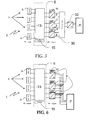
- FIG. 5 relates to a DC distributed PV system with n PV cells, m DC/DC converters 9 having each an associated MPPT control unit 11.
- the outputs of the DC/DC converters 9 are connected to a combine box 30 which output is connected to a DC/AC converter 32.
- Fixed serial or parallel connections of the converters 9 can be considered in the combiner box 30.
- the outputs of the DC/AC converter 32 are connected to load 7.
- FIG. 6 relates to an AC distributed PV system with n PV cells, m DC/AC converters 9 having each an associated MPPT control unit 11. The outputs of the DC/AC converters 9 are connected through common output lines to load 7.
- FIG. 8 relates to a system with n PV cells, m DC/DC converters 9 having each an associated MPPT control unit 11.
- the outputs of the DC/DC converters 9 are connected to a reconfiguration module 3.5 as described in WO2010/070621 in the name of the applicant, the output of the reconfiguration module being connected to an output DC/AC convener 37 which is connected to load 7.
- Dynamically reconfigurable serial and/or parallel connections of the converters 9 outputs are considered with the reconfiguration module 35, leading to an increased reliability in case of a DC/DC converter 9 fault.
- increased reliability and longer life time can be achieved through redundancy in the conversion stage.
- the power produced by functional electricity generating cell 3 connected to a defaulting converter 9 is recovered by rerouting the energy flow to the converters 9 that are in a working operation state.
- Figure 9 differs from the embodiment shown in figure 1 by the fact that the energy routing module 13 comprises furthermore at least 2p outputs, p being a positive integer number and p ⁇ 1 (in the present case p-1), connected to correspondent 2p input terminals of the energy routing module 13 forming a loop connection 40 between said 2p outputs and said 2p input terminals.
- the energy routing module 13 comprises furthermore at least 2p outputs, p being a positive integer number and p ⁇ 1 (in the present case p-1), connected to correspondent 2p input terminals of the energy routing module 13 forming a loop connection 40 between said 2p outputs and said 2p input terminals.
- the embodiment of figure 10 differs from the embodiment of figure 1 by the fact that the outputs of static converters 9 are not connected to the load 7 but to correspondent input terminals of the energy routing module 13.
- the energy routing module 13 comprises two loop connections 40, each comprising a static converter 9 with its MPPT control unit 11.
- the present invention allows optimizing power harvesting from electricity generating cells 3 through adaptive and dynamic rerouting of the energy / power at the output of the electricity generating cells 3 while decreasing the cost of the system in reducing the necessary number of converters 9 and increasing the reliability of the electricity generating system 1.
Priority Applications (10)
| Application Number | Priority Date | Filing Date | Title |
|---|---|---|---|
| EP13290035.8A EP2770539A1 (fr) | 2013-02-20 | 2013-02-20 | Système de gestion électronique de cellules génératrices d'électricité, système de génération d'électricité et procédé de gestion électronique de flux d'énergie |
| KR1020157022339A KR20150120984A (ko) | 2013-02-20 | 2014-02-20 | 전기 생성 전지들을 위한 전자 관리 시스템, 전기 생성 시스템, 및 에너지 흐름을 전자적으로 관리하기 위한 방법 |
| AU2014220730A AU2014220730B2 (en) | 2013-02-20 | 2014-02-20 | Electronic management system for electricity generating cells, electricity generating system and method for electronically managing energy flow |
| JP2015558445A JP6356703B2 (ja) | 2013-02-20 | 2014-02-20 | 発電セルに対する電子管理システム、発電システム、およびエネルギー流を電子的に管理する方法 |
| CN201480016329.5A CN105264671B (zh) | 2013-02-20 | 2014-02-20 | 用于发电电池的电子管理系统、发电系统和用于电子地管理能量流的方法 |
| US14/769,349 US9627893B2 (en) | 2013-02-20 | 2014-02-20 | Electronic management system for electricity generating cells, electricity generating system and method for electronically managing energy flow |
| MX2015010592A MX352335B (es) | 2013-02-20 | 2014-02-20 | Sistema de gestion electronica para celdas generadoras de electricidad, sistema generador de electricidad y metodo para gestionar electronicamente el flujo de energia. |
| PCT/EP2014/053299 WO2014128202A1 (fr) | 2013-02-20 | 2014-02-20 | Système de gestion électronique pour cellules de génération d'électricité, système de génération d'électricité et procédé de gestion électronique d'un flux d'énergie |
| EP14711166.0A EP2959515A1 (fr) | 2013-02-20 | 2014-02-20 | Système de gestion électronique pour cellules de génération d'électricité, système de génération d'électricité et procédé de gestion électronique d'un flux d'énergie |
| ZA2015/05508A ZA201505508B (en) | 2013-02-20 | 2015-07-31 | Electronic management system for electricity generating cells, electricity generating system and method for electronically managing energy flow |
Applications Claiming Priority (1)
| Application Number | Priority Date | Filing Date | Title |
|---|---|---|---|
| EP13290035.8A EP2770539A1 (fr) | 2013-02-20 | 2013-02-20 | Système de gestion électronique de cellules génératrices d'électricité, système de génération d'électricité et procédé de gestion électronique de flux d'énergie |
Publications (1)
| Publication Number | Publication Date |
|---|---|
| EP2770539A1 true EP2770539A1 (fr) | 2014-08-27 |
Family
ID=47877951
Family Applications (2)
| Application Number | Title | Priority Date | Filing Date |
|---|---|---|---|
| EP13290035.8A Withdrawn EP2770539A1 (fr) | 2013-02-20 | 2013-02-20 | Système de gestion électronique de cellules génératrices d'électricité, système de génération d'électricité et procédé de gestion électronique de flux d'énergie |
| EP14711166.0A Withdrawn EP2959515A1 (fr) | 2013-02-20 | 2014-02-20 | Système de gestion électronique pour cellules de génération d'électricité, système de génération d'électricité et procédé de gestion électronique d'un flux d'énergie |
Family Applications After (1)
| Application Number | Title | Priority Date | Filing Date |
|---|---|---|---|
| EP14711166.0A Withdrawn EP2959515A1 (fr) | 2013-02-20 | 2014-02-20 | Système de gestion électronique pour cellules de génération d'électricité, système de génération d'électricité et procédé de gestion électronique d'un flux d'énergie |
Country Status (9)
| Country | Link |
|---|---|
| US (1) | US9627893B2 (fr) |
| EP (2) | EP2770539A1 (fr) |
| JP (1) | JP6356703B2 (fr) |
| KR (1) | KR20150120984A (fr) |
| CN (1) | CN105264671B (fr) |
| AU (1) | AU2014220730B2 (fr) |
| MX (1) | MX352335B (fr) |
| WO (1) | WO2014128202A1 (fr) |
| ZA (1) | ZA201505508B (fr) |
Cited By (3)
| Publication number | Priority date | Publication date | Assignee | Title |
|---|---|---|---|---|
| WO2018002586A1 (fr) * | 2016-06-29 | 2018-01-04 | Xiongwei Liu | Appareil de couplage électrique destiné à être utilisé dans un système d'énergie photovoltaïque solaire et ses procédés de fonctionnement |
| CN107910573A (zh) * | 2017-11-08 | 2018-04-13 | 南京晓庄学院 | 一种可逆燃料电池堆节能装置及控制方法 |
| EP4032180A4 (fr) * | 2019-09-16 | 2023-06-21 | WH Mechanical Engineering Inc. | Appareil, procédé et article destinés à maximiser le courant de charge solaire grâce à l'usage d'un ou de plusieurs câbles multibrins dans un réseau solaire dont les panneaux solaires sont connectés en une combinaison série et parallèle |
Families Citing this family (13)
| Publication number | Priority date | Publication date | Assignee | Title |
|---|---|---|---|---|
| US9985572B2 (en) * | 2015-04-30 | 2018-05-29 | Glenn Arthur Hastings | Solar roadway system and method |
| JP2017059094A (ja) * | 2015-09-18 | 2017-03-23 | トヨタ自動車株式会社 | 太陽電池の昇圧機能付き発電動作点制御回路装置 |
| US10651735B2 (en) | 2017-02-06 | 2020-05-12 | Futurewei Technologies, Inc. | Series stacked DC-DC converter with serially connected DC power sources and capacitors |
| US10665743B2 (en) * | 2017-02-16 | 2020-05-26 | Futurewei Technologies, Inc. | Distributed/central optimizer architecture |
| CN106712698A (zh) * | 2017-03-01 | 2017-05-24 | 北京天恒长鹰科技股份有限公司 | 一种多阶混合太阳能电池阵及其组合供电方法 |
| US10333314B2 (en) | 2017-04-17 | 2019-06-25 | Futurewei Technologies, Inc. | Multiple buck stage single boost stage optimizer |
| KR102282617B1 (ko) * | 2017-05-15 | 2021-07-28 | 다이너파워 컴퍼니 엘엘씨 | 태양광 에너지용 에너지 저장 시스템 및 태양광 에너지 저장 방법 |
| CN108988378A (zh) * | 2017-05-30 | 2018-12-11 | 太阳能安吉科技有限公司 | 在电力系统中路由电力 |
| JP7173128B2 (ja) * | 2018-03-29 | 2022-11-16 | 住友電気工業株式会社 | 発電部再配置演算装置および演算処理方法 |
| DE102018127132A1 (de) * | 2018-10-30 | 2020-04-30 | Sma Solar Technology Ag | Wechselrichter mit mindestens zwei Gleichspannungswandlern und Verwendung eines solchen Wechselrichters in einer Photovoltaikanlage |
| DE102018127130A1 (de) | 2018-10-30 | 2020-04-30 | Sma Solar Technology Ag | Wechselrichter mit mindestens zwei Gleichspannungswandlern |
| JP7249893B2 (ja) * | 2019-07-01 | 2023-03-31 | 大和ハウス工業株式会社 | 電力供給システム |
| CN112054503B (zh) * | 2020-09-27 | 2022-01-04 | 武汉大学 | 一种基于串联光伏模块环形功率均衡系统的功率均衡方法 |
Citations (9)
| Publication number | Priority date | Publication date | Assignee | Title |
|---|---|---|---|---|
| US6350944B1 (en) | 2000-05-30 | 2002-02-26 | Hughes Electronics Corporation | Solar module array with reconfigurable tile |
| WO2008076301A1 (fr) | 2006-12-15 | 2008-06-26 | Miasole | Module photovoltaïque utilisant un circuit souple pour reconfiguration |
| WO2009060273A1 (fr) * | 2007-11-08 | 2009-05-14 | Harald Hauf | Procédé de fonctionnement et dispositif de commande d'une installation énergétique à modules photovoltaïques |
| US20100109442A1 (en) * | 2008-10-30 | 2010-05-06 | Asea Brown Boveri, S.A. | System and Method for Energy Optimization in Photovoltaic Generators |
| WO2010070621A1 (fr) | 2008-12-18 | 2010-06-24 | Centre National De La Recherche Scientifique | Systeme de gestion electronique de cellules photovoltaiques |
| EP2337184A2 (fr) * | 2009-12-15 | 2011-06-22 | Samsung SDI Co., Ltd. | Système de stockage d'énergie raccordé au réseau et son procédé de commande |
| EP2372487A2 (fr) * | 2010-04-01 | 2011-10-05 | Huawei Technologies Co., Ltd. | Système de génération de lumière solaire, dispositif de contrôle et son procédé de contrôle |
| FR2961035A1 (fr) * | 2010-06-04 | 2011-12-09 | Aeg Power Solutions Bv | Dispositif de connexion matricielle pour panneaux photovoltaiques et/ou eoliennes |
| EP2518855A2 (fr) * | 2011-04-29 | 2012-10-31 | General Electric Company | Coordination de commutation de convertisseurs CC-CC distribués pour des centrales photovoltaïques hautement efficaces |
Family Cites Families (16)
| Publication number | Priority date | Publication date | Assignee | Title |
|---|---|---|---|---|
| EP0703652B1 (fr) * | 1994-09-21 | 1998-06-03 | Inventio Ag | Méthode et appareil pour une allocation variable d'un convertiseur en fonctionemment avec au moins une charge |
| JPH1069321A (ja) * | 1996-08-27 | 1998-03-10 | Honda Motor Co Ltd | 太陽光発電装置 |
| JP2001268800A (ja) * | 2000-03-16 | 2001-09-28 | Kawasaki Steel Corp | 太陽光発電制御方法及び装置 |
| JP3656531B2 (ja) * | 2000-08-31 | 2005-06-08 | 松下電工株式会社 | 太陽光発電システム |
| US20100116325A1 (en) * | 2008-11-12 | 2010-05-13 | Mehrdad Nikoonahad | High efficiency solar panel and system |
| CA2746490A1 (fr) * | 2008-12-18 | 2010-07-15 | Abb Research Ltd. | Dispositif convertisseur et procede de commande d'un dispositif convertisseur |
| JP5302096B2 (ja) * | 2009-05-15 | 2013-10-02 | 株式会社Nttファシリティーズ | 太陽光発電システム及び制御方法 |
| FR2953997B1 (fr) * | 2009-12-11 | 2012-01-20 | Centre Nat Rech Scient | Systeme de gestion electronique de cellules photovoltaiques avec seuils adaptes |
| EP2518885B1 (fr) | 2009-12-24 | 2017-07-05 | Panasonic Corporation | Convertisseur de puissance possédant un élément de commutation à semi-conducteurs |
| DE102010017747A1 (de) * | 2010-05-03 | 2011-11-03 | Sma Solar Technology Ag | Verfahren zur Begrenzung der Generatorspannung einer photovoltaischen Anlage im Gefahrenfall und photovoltaische Anlage |
| US8853886B2 (en) * | 2010-06-09 | 2014-10-07 | Tigo Energy, Inc. | System for use of static inverters in variable energy generation environments |
| US9299861B2 (en) * | 2010-06-15 | 2016-03-29 | Tenksolar, Inc. | Cell-to-grid redundandt photovoltaic system |
| JP2012090516A (ja) * | 2010-10-15 | 2012-05-10 | Sanyo Electric Co Ltd | 切替回路、制御装置および発電システム |
| JP2012208725A (ja) * | 2011-03-30 | 2012-10-25 | National Institute Of Advanced Industrial & Technology | 太陽光発電システム |
| JP5748213B2 (ja) * | 2011-06-22 | 2015-07-15 | コア・テック株式会社 | 太陽光発電システム |
| US9379543B2 (en) * | 2012-04-10 | 2016-06-28 | Sol Chip Ltd. | Integrated circuit energy harvester |
-
2013
- 2013-02-20 EP EP13290035.8A patent/EP2770539A1/fr not_active Withdrawn
-
2014
- 2014-02-20 EP EP14711166.0A patent/EP2959515A1/fr not_active Withdrawn
- 2014-02-20 CN CN201480016329.5A patent/CN105264671B/zh not_active Expired - Fee Related
- 2014-02-20 MX MX2015010592A patent/MX352335B/es active IP Right Grant
- 2014-02-20 AU AU2014220730A patent/AU2014220730B2/en not_active Ceased
- 2014-02-20 US US14/769,349 patent/US9627893B2/en active Active
- 2014-02-20 JP JP2015558445A patent/JP6356703B2/ja not_active Expired - Fee Related
- 2014-02-20 KR KR1020157022339A patent/KR20150120984A/ko not_active Application Discontinuation
- 2014-02-20 WO PCT/EP2014/053299 patent/WO2014128202A1/fr active Application Filing
-
2015
- 2015-07-31 ZA ZA2015/05508A patent/ZA201505508B/en unknown
Patent Citations (9)
| Publication number | Priority date | Publication date | Assignee | Title |
|---|---|---|---|---|
| US6350944B1 (en) | 2000-05-30 | 2002-02-26 | Hughes Electronics Corporation | Solar module array with reconfigurable tile |
| WO2008076301A1 (fr) | 2006-12-15 | 2008-06-26 | Miasole | Module photovoltaïque utilisant un circuit souple pour reconfiguration |
| WO2009060273A1 (fr) * | 2007-11-08 | 2009-05-14 | Harald Hauf | Procédé de fonctionnement et dispositif de commande d'une installation énergétique à modules photovoltaïques |
| US20100109442A1 (en) * | 2008-10-30 | 2010-05-06 | Asea Brown Boveri, S.A. | System and Method for Energy Optimization in Photovoltaic Generators |
| WO2010070621A1 (fr) | 2008-12-18 | 2010-06-24 | Centre National De La Recherche Scientifique | Systeme de gestion electronique de cellules photovoltaiques |
| EP2337184A2 (fr) * | 2009-12-15 | 2011-06-22 | Samsung SDI Co., Ltd. | Système de stockage d'énergie raccordé au réseau et son procédé de commande |
| EP2372487A2 (fr) * | 2010-04-01 | 2011-10-05 | Huawei Technologies Co., Ltd. | Système de génération de lumière solaire, dispositif de contrôle et son procédé de contrôle |
| FR2961035A1 (fr) * | 2010-06-04 | 2011-12-09 | Aeg Power Solutions Bv | Dispositif de connexion matricielle pour panneaux photovoltaiques et/ou eoliennes |
| EP2518855A2 (fr) * | 2011-04-29 | 2012-10-31 | General Electric Company | Coordination de commutation de convertisseurs CC-CC distribués pour des centrales photovoltaïques hautement efficaces |
Non-Patent Citations (2)
| Title |
|---|
| SCIENCEDIRECT SOLAR ENERGY, vol. 84, 2010, pages 1175 - 1186 |
| VELASCO-QUESADA G ET AL: "Electrical PV Array Reconfiguration Strategy for Energy Extraction Improvement in Grid-Connected PV Systems", IEEE TRANSACTIONS ON INDUSTRIAL ELECTRONICS, IEEE SERVICE CENTER, PISCATAWAY, NJ, USA, vol. 56, no. 11, 1 November 2009 (2009-11-01), pages 4319 - 4331, XP011270847, ISSN: 0278-0046, DOI: 10.1109/TIE.2009.2024664 * |
Cited By (5)
| Publication number | Priority date | Publication date | Assignee | Title |
|---|---|---|---|---|
| WO2018002586A1 (fr) * | 2016-06-29 | 2018-01-04 | Xiongwei Liu | Appareil de couplage électrique destiné à être utilisé dans un système d'énergie photovoltaïque solaire et ses procédés de fonctionnement |
| US11018622B2 (en) | 2016-06-29 | 2021-05-25 | Entrust Smart Home Microgrid Ltd. | Electrical coupling apparatus for use in a solar photovoltaic power system and methods of operating the same |
| CN107910573A (zh) * | 2017-11-08 | 2018-04-13 | 南京晓庄学院 | 一种可逆燃料电池堆节能装置及控制方法 |
| CN107910573B (zh) * | 2017-11-08 | 2020-10-09 | 南京晓庄学院 | 一种可逆燃料电池堆节能装置及控制方法 |
| EP4032180A4 (fr) * | 2019-09-16 | 2023-06-21 | WH Mechanical Engineering Inc. | Appareil, procédé et article destinés à maximiser le courant de charge solaire grâce à l'usage d'un ou de plusieurs câbles multibrins dans un réseau solaire dont les panneaux solaires sont connectés en une combinaison série et parallèle |
Also Published As
| Publication number | Publication date |
|---|---|
| CN105264671B (zh) | 2017-10-24 |
| US9627893B2 (en) | 2017-04-18 |
| MX352335B (es) | 2017-11-21 |
| ZA201505508B (en) | 2021-05-26 |
| MX2015010592A (es) | 2016-07-18 |
| JP2016516382A (ja) | 2016-06-02 |
| WO2014128202A1 (fr) | 2014-08-28 |
| AU2014220730B2 (en) | 2017-08-31 |
| CN105264671A (zh) | 2016-01-20 |
| AU2014220730A1 (en) | 2015-08-20 |
| EP2959515A1 (fr) | 2015-12-30 |
| US20160006250A1 (en) | 2016-01-07 |
| KR20150120984A (ko) | 2015-10-28 |
| JP6356703B2 (ja) | 2018-07-11 |
Similar Documents
| Publication | Publication Date | Title |
|---|---|---|
| US9627893B2 (en) | Electronic management system for electricity generating cells, electricity generating system and method for electronically managing energy flow | |
| KR101708388B1 (ko) | 태양전지를 위한 전자 관리 시스템 | |
| KR101520981B1 (ko) | 태양 전지 설비를 위한 국부화된 파워 포인트 옵티마이저 | |
| US10651787B2 (en) | Reconfigurable photovoltaic module | |
| US20110031816A1 (en) | Photovoltaic unit, a dc-dc converter therefor, and a method of operating the same | |
| US8664797B2 (en) | Photovoltaic assembly and method of operating a photovoltaic assembly | |
| JP6236582B2 (ja) | 適合するしきい値を有する太陽電池の電子的管理システム | |
| KR101838760B1 (ko) | 기상의 함수로서 광기전 전지의 전자 관리를 위한 시스템 | |
| KR101445711B1 (ko) | 태양광발전 시스템 | |
| JP6155288B2 (ja) | 単純化された接続を備える再生可能エネルギーユニット | |
| KR101638753B1 (ko) | 바이패스 다이오드가 없는 태양광 발전 시스템 | |
| KR20200113877A (ko) | 태양광 패널 출력전력 변동에 대응하는 직류전류 합산제어가 가능한 태양광 발전 시스템 | |
| US20230327452A1 (en) | Switching matrix for reconfigurable pv modules and systems | |
| Di Dio et al. | A new control system prototype for the energy production maximization of a unequally irradiated PV system | |
| ES2727790A1 (es) | Convertidor híbrido y su método de control | |
| Elanchezhian et al. | Design of two-stage soft-switched module Inverter for Photovoltaic applications | |
| Al-rawashdeh et al. | Evaluation of energy harvest increase by distributed maximum power point tracking | |
| KR20170029199A (ko) | 태양광 발전 장치 | |
| JP5912417B2 (ja) | 太陽光発電装置 | |
| KR20200113878A (ko) | 승압기를 이용하여 태양광 패널 출력전력 변동에 대응하는 직류전류 합산제어가 가능한 태양광 발전 시스템 | |
| KR20200122557A (ko) | 가변 어레이를 이용한 태양광 발전 시스템 | |
| Liu et al. | Self-reconfiguration strategy for energy extraction improvement of island renewable energy sources | |
| Kadali et al. | A Distributed Maximum Power Point Control For Efficiency Enhancement Of Photovoltaic System |
Legal Events
| Date | Code | Title | Description |
|---|---|---|---|
| PUAI | Public reference made under article 153(3) epc to a published international application that has entered the european phase |
Free format text: ORIGINAL CODE: 0009012 |
|
| 17P | Request for examination filed |
Effective date: 20130220 |
|
| AK | Designated contracting states |
Kind code of ref document: A1 Designated state(s): AL AT BE BG CH CY CZ DE DK EE ES FI FR GB GR HR HU IE IS IT LI LT LU LV MC MK MT NL NO PL PT RO RS SE SI SK SM TR |
|
| AX | Request for extension of the european patent |
Extension state: BA ME |
|
| STAA | Information on the status of an ep patent application or granted ep patent |
Free format text: STATUS: THE APPLICATION IS DEEMED TO BE WITHDRAWN |
|
| 18D | Application deemed to be withdrawn |
Effective date: 20150228 |