EP2587334A1 - Configuration PV reconfigurable - Google Patents
Configuration PV reconfigurable Download PDFInfo
- Publication number
- EP2587334A1 EP2587334A1 EP20110186415 EP11186415A EP2587334A1 EP 2587334 A1 EP2587334 A1 EP 2587334A1 EP 20110186415 EP20110186415 EP 20110186415 EP 11186415 A EP11186415 A EP 11186415A EP 2587334 A1 EP2587334 A1 EP 2587334A1
- Authority
- EP
- European Patent Office
- Prior art keywords
- module
- substrings
- converters
- cells
- connections
- Prior art date
- Legal status (The legal status is an assumption and is not a legal conclusion. Google has not performed a legal analysis and makes no representation as to the accuracy of the status listed.)
- Withdrawn
Links
- 238000013461 design Methods 0.000 claims description 31
- 238000000034 method Methods 0.000 claims description 15
- 238000004590 computer program Methods 0.000 claims description 5
- 230000008707 rearrangement Effects 0.000 claims description 2
- 230000000638 stimulation Effects 0.000 claims description 2
- 238000009434 installation Methods 0.000 abstract description 4
- 210000004027 cell Anatomy 0.000 description 112
- 230000015654 memory Effects 0.000 description 12
- 238000004519 manufacturing process Methods 0.000 description 10
- 230000006870 function Effects 0.000 description 8
- 238000005457 optimization Methods 0.000 description 7
- 230000002829 reductive effect Effects 0.000 description 7
- 230000008901 benefit Effects 0.000 description 6
- 230000000694 effects Effects 0.000 description 6
- 238000013459 approach Methods 0.000 description 5
- 230000015556 catabolic process Effects 0.000 description 5
- 238000006731 degradation reaction Methods 0.000 description 5
- 230000004069 differentiation Effects 0.000 description 4
- 238000005286 illumination Methods 0.000 description 4
- 238000002955 isolation Methods 0.000 description 3
- 230000003287 optical effect Effects 0.000 description 3
- 230000036961 partial effect Effects 0.000 description 3
- 238000013138 pruning Methods 0.000 description 3
- 230000006399 behavior Effects 0.000 description 2
- 238000004364 calculation method Methods 0.000 description 2
- 238000006243 chemical reaction Methods 0.000 description 2
- 230000001276 controlling effect Effects 0.000 description 2
- 230000006378 damage Effects 0.000 description 2
- 230000005611 electricity Effects 0.000 description 2
- 230000006872 improvement Effects 0.000 description 2
- 230000003993 interaction Effects 0.000 description 2
- 230000000670 limiting effect Effects 0.000 description 2
- 238000012423 maintenance Methods 0.000 description 2
- 230000002093 peripheral effect Effects 0.000 description 2
- 230000000644 propagated effect Effects 0.000 description 2
- 230000009467 reduction Effects 0.000 description 2
- 239000007787 solid Substances 0.000 description 2
- 241000489569 Mandevilla x amabilis Species 0.000 description 1
- 210000004460 N cell Anatomy 0.000 description 1
- 230000032683 aging Effects 0.000 description 1
- 230000004075 alteration Effects 0.000 description 1
- 238000004458 analytical method Methods 0.000 description 1
- 230000003042 antagnostic effect Effects 0.000 description 1
- 230000015572 biosynthetic process Effects 0.000 description 1
- 239000004020 conductor Substances 0.000 description 1
- 238000013500 data storage Methods 0.000 description 1
- 230000004064 dysfunction Effects 0.000 description 1
- 230000007613 environmental effect Effects 0.000 description 1
- 238000011156 evaluation Methods 0.000 description 1
- 230000005284 excitation Effects 0.000 description 1
- 230000029142 excretion Effects 0.000 description 1
- 230000004807 localization Effects 0.000 description 1
- 230000007257 malfunction Effects 0.000 description 1
- 239000000463 material Substances 0.000 description 1
- 230000005055 memory storage Effects 0.000 description 1
- 238000012545 processing Methods 0.000 description 1
- 230000001105 regulatory effect Effects 0.000 description 1
- 230000001932 seasonal effect Effects 0.000 description 1
- 238000000926 separation method Methods 0.000 description 1
- 230000003068 static effect Effects 0.000 description 1
- 238000003860 storage Methods 0.000 description 1
- 230000001550 time effect Effects 0.000 description 1
- 230000005919 time-dependent effect Effects 0.000 description 1
- 230000000007 visual effect Effects 0.000 description 1
Images


Classifications
-
- H—ELECTRICITY
- H01—ELECTRIC ELEMENTS
- H01L—SEMICONDUCTOR DEVICES NOT COVERED BY CLASS H10
- H01L31/00—Semiconductor devices sensitive to infrared radiation, light, electromagnetic radiation of shorter wavelength or corpuscular radiation and specially adapted either for the conversion of the energy of such radiation into electrical energy or for the control of electrical energy by such radiation; Processes or apparatus specially adapted for the manufacture or treatment thereof or of parts thereof; Details thereof
- H01L31/02—Details
- H01L31/02016—Circuit arrangements of general character for the devices
- H01L31/02019—Circuit arrangements of general character for the devices for devices characterised by at least one potential jump barrier or surface barrier
- H01L31/02021—Circuit arrangements of general character for the devices for devices characterised by at least one potential jump barrier or surface barrier for solar cells
-
- G—PHYSICS
- G05—CONTROLLING; REGULATING
- G05F—SYSTEMS FOR REGULATING ELECTRIC OR MAGNETIC VARIABLES
- G05F1/00—Automatic systems in which deviations of an electric quantity from one or more predetermined values are detected at the output of the system and fed back to a device within the system to restore the detected quantity to its predetermined value or values, i.e. retroactive systems
- G05F1/66—Regulating electric power
- G05F1/67—Regulating electric power to the maximum power available from a generator, e.g. from solar cell
-
- Y—GENERAL TAGGING OF NEW TECHNOLOGICAL DEVELOPMENTS; GENERAL TAGGING OF CROSS-SECTIONAL TECHNOLOGIES SPANNING OVER SEVERAL SECTIONS OF THE IPC; TECHNICAL SUBJECTS COVERED BY FORMER USPC CROSS-REFERENCE ART COLLECTIONS [XRACs] AND DIGESTS
- Y02—TECHNOLOGIES OR APPLICATIONS FOR MITIGATION OR ADAPTATION AGAINST CLIMATE CHANGE
- Y02E—REDUCTION OF GREENHOUSE GAS [GHG] EMISSIONS, RELATED TO ENERGY GENERATION, TRANSMISSION OR DISTRIBUTION
- Y02E10/00—Energy generation through renewable energy sources
- Y02E10/50—Photovoltaic [PV] energy
- Y02E10/56—Power conversion systems, e.g. maximum power point trackers
Definitions
- the present invention relates to PV (Photovoltaic) modules, arrangements and installations, and to methods of designing and constructing such PV modules.
- a photovoltaic system (or PV system) is a system which uses many solar cells usually in the form of one or more solar panels to convert sunlight into electricity. It can comprise multiple components, including photovoltaic modules, mechanical and electrical connections and mountings and means of regulating and/or modifying the electrical output as well as means to track the sun.
- the efficiency of the solar system is reduced during dynamic conditions by time-dependent effects.
- the efficiency of today's power circuits is high, although the overall efficiency is strongly affected from varying factors such as partial shading. In rooftop applications these problems become more important.
- Known configurations that are used in today's systems are not dealing with these problems effectively during operation, i.e. at the run-time of the system.
- Maximum power point tracking is a technique that solar inverters use to get the maximum possible power from the PV system.
- Solar cells have a complex relationship between solar irradiation, temperature and total resistance that produces a non-linear output efficiency known as the I-V curve. It is the purpose of the MPPT system to sample the output of the cells and apply a resistance (load) to obtain maximum power for any given environmental conditions. Essentially, this defines the current that the inverter should draw from the PV system in order to get the maximum possible power.
- the MPP tracker is vital for a large number of modules, making the module mismatching a crucial factor. Even when the control is decentralized at the module level, the efficiency is further reduced and reliability issues make these configurations inefficient.
- WO2005/112551 describes an auxiliary power source connected to each PV module of series connected strings. In case of partial shading, this source supplies the necessary power in order to prevent a temporary shut-down.
- the MPPT controls the switches of the power source.
- Modules which are widely used nowadays are uniform. All cells of commercial modules are permanently connected in series and the controls of the system are mainly situated in the central or local converters. As the excitation of the PV system is not uniform (e.g. non-uniform irradiation, and/or temperature), a small group of cells can cause the module to operate well below optimum. In the case of total destruction or shading of some cells, the whole module is potentially disconnected from the system leading to a significant loss of power.
- several proposals are introduced which use more controls than purely in the converter. They focus mainly on adding local control at the module level. Dynamic interconnections of the cells within the module have been introduced as well. Known module configurations are however uniform.
- US20090079412 describes an apparatus and method controlling the output of a PV array which disclose that a high enough output voltage can be obtained by uniformly switching N parallel connected cell strings into N/M parallel connected groups of M times longer cell strings. Every MPTT or controller is purely locally driven, even when it is conceptually used in an intra-module manner. It is noticeable in the array that there are long conductors which span from one end of strings of cells to the other.
- An object of the present invention is to provide a smart PV module and method of designing the same.
- An advantage of embodiments of the present invention is an increase in the performance such as a better energy-yield of the PV system.
- a useful cost function which can be used to evaluate different configurations of the module is a three dimensional objective space of restricted production and maintenance cost, increased yearly energy yield, and increased life time.
- the above object is achieved by a PV module with an array of PV cells whereby the module is reconfigurable, allowing different configurations to be applied after installation and during operation, i.e. at run-time.
- the run time configuration of the module has controllable devices.
- the main controllable devices are any of (individually or in combination):
- a substring can be either a column or a row of the module. Where further refinement is required the columns and rows can be further divided, i.e. by a vertical split of the column or horizontal split of the row.
- the present invention provides a reconfigurable arrangement of photovoltaic cells in a module having at least one DC-DC converter connectable to the cells, comprising:
- the means to reconfigure can comprise first switches operable to form the parallel and/or series connections of substrings in groupings.
- the arrangement can include a plurality of DC-DC converters, wherein the means to reconfigure comprise second switches located between the substrings and the DC-DC converters.
- the means to reconfigure may preferably comprise third switches located between the DC-DC converters.
- a reconfigurable non-symmetric configuration comprising one or more modules, such as photovoltaic modules, and a controller, wherein the controller is adapted to optimize performance real-time in terms of two or more predetermined design templates matching a layout of the configuration, wherein each module comprises an array of n by m cells, n,m both being larger than 2, each module comprising elements selected from a group comprising or consisting of a DC-converter, an active (or passive) bypass diode, a switch, a cell, and a connector, wherein:
- the present invention also provides a method of operating a reconfigurable arrangement as described above, comprising the steps of:
- the present invention also includes a computer program product having instructions to be executed on a computer to perform a method described above.
- the computer program product may be stored on a non-transitory signal medium such as a magnetic disk, an optical disk or in a solid state memory.
- reconfigurable refers to an option to configure e.g. a module in principle at any point in time to another configuration, for instance based on input, in order to achieve a certain goal, such as improved performance. Not all elements of a configuration can be reconfigured, such as the present cells are fixed. Some elements, specifically switches, connectors and bypasses can be reconfigured, i.e. forming a connection or not.
- non-symmetric or “non-uniform” refers to absence of symmetry elements for a module and/or configuration as a whole, taking in account all elements claimed, such as a two-fold axis, a mirror plane, etc. The term does not exclude local symmetry elements.
- the present configuration relates to one or more modules optionally being inter-connected.
- An example thereof is a PV-module for converting light into electricity.
- modules have standardized sizes, e.g. in terms of cells and/or in terms of dimensions.
- Modules may be added to a configuration, like building-blocks, and are typically interconnected.
- a key issue of the present invention is to determine one or more design templates.
- Embodiments of the present invention provide templates that can be adapted in order to have different real physical configurations, which allows more flexibility.
- the concept of the flexible/hybrid series or parallel substring connections, the placement of the local dc/dc converters, the vertical split options, and the active controlled bypass diodes can be combined in a very flexible way to increase the overall efficiency of the module. It is important to include the constraints propagated in a uni-directional way between these different options while combining them. Constraints can be compatibility of the non-uniform subset selection in previous steps.
- a fully embodied template comprises all possible elements of the present invention, such as a switch between any two elements, a connector between any two elements, etc.
- a design template can be regarded as a subset from the fully embodied template, which design template takes into account boundary conditions, such as shadow formed by an object nearby a configuration, which shadow shifts in time and during seasons. Such boundary conditions indicate a need for a configuration being reconfigurable in order to adapt to changing situations, such as moving shadows.
- a design template also takes into account seasonal situations, such as snow, blanking for instance part or whole of a module. It can also accommodate (fast) temperature transients and degradation of the materials.
- a design template is further optimized in terms of performance of the configuration at a given point in time.
- a controller In order to reconfigure the present configuration real-time (or run time) a controller is provided.
- the controller is adapted to reconfigure one or more modules, and/or one or more groups of cells, specifically by adapting one or more of a switch, a connection, and a bypass.
- the present controller is adapted to optimize performance real-time in terms of one or more predetermined design templates matching a layout of the configuration; the controller can be regarded as switching from layout to layout. Optimization implies that a controller has data available as input, and further has information on the present configuration as well. Based on this information the controller may adapt the present configuration in order to e.g. optimize performance thereof. Such optimization may be performed real-time, that is in a matter of seconds or less.
- Optimization is in fact only limited by a time the controller needs to determine an optimal configuration and by a time needed to switch switches and/or connect/disconnect connectors and/or to activate/deactivate bypasses.
- Typical switching times are in the order of milliseconds up to (fractions of) seconds, typical controller times are also in the order of milliseconds up to (fractions of) seconds, typically depending on a CPU or the like used. From an other point of view switching and controlling is preferably limited to some extend, as electrical components, such as dc-converters, diodes, etc. should not be loaded/unloaded to often/quickly.
- each module comprises an array of n by m cells, such as a rectangular array.
- n By dividing the size of the array into n by m cells, such as a rectangular array.
- m By dividing the size of the array into n by m cells, such as a rectangular array.
- n m
- n m
- m being interchangeable.
- the number of cells in an array is typically in the order of 12-120, but is not limited thereto.
- Each module is capable of converting light (photons) into electrical current/voltage, which current is typically converted by a transformer/converter, e.g. from DC to AC, in order to have a current available for use.
- a transformer/converter e.g. from DC to AC
- Each module comprises at least one first group of cells connected in series and/or at least one second group of cells connected in parallel.
- cells in a module are connected to one and another, in one parallel or in series, or both.
- Not all cell of a module need to be connected.
- the present configuration may contain at any point in time a certain number of cells not being connected for one or more of various reasons, such as malfunction, dysfunction, external shadow covering one or more cells, pollution, such as birds excretion, etc.
- an optimal configuration relates to a combination of cells connected in series as well as cells connected in parallel.
- the number of cells in the first and/or second group may vary due to e.g. boundary conditions.
- any group of cells may comprise any number of cells, the number being smaller or equal to the number of an array (n*m). It is observed that not all groups may have a number of cells equal to that of an array, as such a configuration is symmetrical.
- Each module comprises at least one third group of cells comprising one or more DC-converters. For converting current/voltage from DC to e.g. AC at least one converter is provided.
- An advantage of embodiments of the present invention is that the fabrication cost can be significantly reduced by introducing strong non-uniformity into the topology.
- the non-uniformity applies to wires and switches and also DC-converters and bypass diodes.
- Groups of cells can be formed by parallel or series connections of the substrings using switches and wires positioned at strategic places which still allow improvement or even maximization of the energy-yield. Connections are removed from the design for which the expected life-time gain is insufficiently higher than the additional cost of the required overhead components.
- Each module preferably has local DC/DC conversion and the number of converters is preferably linked with the number of substrings of the module but still limited to reduce the overhead. Which converters are in use for a given run-time situation depends on the groups of substrings which have been formed.
- the local converters can preferably be connected either in parallel or series according to the power demand of the system from the module.
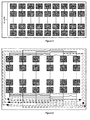
- light grey boxes are PV cells of substrings of the modules, whereas dark grey boxes are local DC/DC converters.
- the present invention relates to PV modules and installations, to methods of designing and constructing such PV modules, whereby the PV modules are reconfigurable at run-time.
- switches are adapted to devise, connect and reconnect modules and/or substrings, one or more connectors for connecting modules and/or substrings.
- Switches can be configured between DC-DC converter and substring and between the substrings in different combinations like series, parallel, symmetric and asymmetric.
- Each switch has a state, such as "on” or “off ⁇ , i.e. connected or disconnected. States of the switches are controlled such as by a knob-controller depending on the phase and the current imbalance in each substring.
- the present configuration can be reconfigured real time, i.e. instantly, adapting for instance to a changing situation. For instance, when a substring is partially shaded or any imbalance in a current appears then the substring connected with its own DC-DC converter via a switch and it is isolated from all other substrings. So a mismatch effect can be avoided.
- a disadvantage is that a current generated may be less.
- An advantage is that the current from that substring will be added to the total current of the module which helps to improve overall efficiency.
- the substring can be completely isolated from the module.
- Imbalance of a current and overhead of the circuitry can be compared at the run time by the controller. Depending on both factors mentioned, the controller will determine whether a photon generated current in a substring or group of them, can be added to a total current or not. For active bypass diodes the control granularity is different and can be up to neighboring cells.
- Advantages of embodiments of the present invention are the attractive trade-off point between fabrication cost and the increased energy yield, and these can be used for evaluation of actual PV modules and an installed PV system.
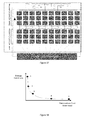
- An aim is to increase the annual energy yield while the fabrication cost overhead remains sufficiently low. Optimization of all cost aspects simultaneously is not possible. It is evident that by pursuing optimization of one cost aspect, the other tends to worsen.
- figure 1.1 shows the results for several configurations. The two axes of the graph represent the fabrication cost overhead and the energy yield loss. The purpose is to track the Pareto point which is the optimum choice. Commercial modules have low fabrication cost but have high energy loss (Point 1).
- Point 2 The potential connection of all neighboring cells has low energy loss but translates to a high fabrication cost (Point 2).
- Point 3 can be the localization of the DC/DC conversion with no dynamic reconfiguration of the module and Point 4 the decrease of the potential connections of the cells within the module.
- Point 5 is an intermediate Pareto Point of the curve. Configurations according to embodiments of the present invention, can be designed to lie different positions on the Pareto curve, e.g. by changing the number of DC/DC converters, the number of vertical splits and the number of bypass diodes. In this way we can in principle cover the range between point 3 and 4.
- the purpose of dividing the module to substrings is to have a run-time variable (called "knob-controlled") series/parallel or hybrid connection that allows the grouping of substrings which function under similar conditions in order to avoid mismatch effects that reduce energy-yield or to improve the module life time (component reliability impact).
- Each group of substrings is connected to a local dc/dc converter where the duty cycle, and thus the voltage, is preferably set to the near-optimal value for the specific group of substrings.
- a substring preferably includes as few cells as possible in order to allow more flexibility to the module.
- the selection of the substrings preferably takes into account the length of the wires required for their interconnection and their intra-connection. It is evident that adding run-time variable ("knob-controlled") connections at the edges of the module is less costly than changing the electrical connections within the inner part of the module.
- the columns or the rows of the module are the best options to be used as substrings for the N*M mesh-shaped modules which are being targeted. Based on the above, the selection is preferably according to the length (in number of cells) of the columns and rows of the module. Another criterion, can be whether the number of rows and columns are odd or even.
- An even number of substrings is more optimal, as in the all series connection of the module the inputs and the outputs are on the same side of the module and are more easily connected to the converters.
- N N by M module where N ⁇ M and M is even
- a preferred e.g. optimal choice is to have M substrings of N cells. If M is an odd number, a trade-off exists in terms of having small substrings or an even number of substrings. The case where both N and M are odd numbers is considered less preferred, though in that case the smaller dimension would be formed into substrings.
- a module of 6 by 9 cells can have either 6 substrings of 9 cells choosing to have an even number of substrings either 9 substrings of 6 cells in order to have a smaller length of substrings.
- Two options of forming the substrings in a simple structure are illustrated in figures 4 and 5 .
- Embodiments of the present invention include different ways of dividing the module into substrings, e.g. in a "Vertical split", which provides another approach of handling the trade-off described above relating to even number of substrings ⁇ small substrings. More complex structures can include hybrids.
- the current flow is indicated by "out” and "in” on the ends of the substring.
- figure 6 all possible series connections of the substrings are shown. In the series connection, an "out" pin can be directly connected to an "in” pin and vice versa.
- the continuous lines in figure 6 indicate wire connections which remain on the same side of the module, while the long-dashed wires connect an "in” pin with an “out” pin on different sides of the module.
- the current remains identical for all cells while the voltage adds up with each additional cell.
- the connections which are possible should be limited by removing, in one or more ways that will be described below, long wires which impose too much overhead compared to their expected gain, and optionally removing connections which are less needed because they can be replaced by others that provide nearly the same overall gain.
- the switches and other added components can, as much as possible, be "hidden" from the dominant active paths in the topology.
- the dominant active paths are the series connections or other often used paths as determined at the design stage used in most occurring practical scenarios. In conventional approaches, these added components do contribute continuously to the dominant active paths and hence cause a near-permanent overhead in power and reliability losses.
- Embodiments of the present invention allow avoidance of this problem by the choice of run-time variable ("knob-controlled") topology.
- Embodiments of the present invention reduce the overhead, which is introduced by the presence of wires, by removing (i.e. not having or using) the longest wires.
- the wires which are "crossing" the module, the long-dashed wires are removed (see embodiment of figure 8 compared to Fig. 6 ).
- the PV module is adapted so that all substrings are connected only with substrings which allow opposite current flow.
- each substring is connected on each side of the module with 3 substrings.
- the remaining wires are still quite long, especially if the general case of N by M cells is considered. In that case, in embodiments of the present invention that are non-symmetric or non-uniform, even more pruning is carried out, e.g. removal of all wires that extend beyond a user-defined threshold length.
- That threshold length can be selected by a computation based on an analysis of which wire length overhead cannot increase the energy-yield with a sufficient gain.
- the threshold can be determined by using a cost function that combines the energy-yield and the cost gain for example. This will be illustrated below in more detail.
- each substring which in this case means each column, is connected with all the substrings of opposite current flow on the same side of the module. So each substring has connections with N/2 substrings on each side of the module, as shown in the embodiment of figure 9 .
- embodiments of the present invention assign a maximum length that has to be respected.
- the proposed upper bound for the maximum length can be selected as N/2. If x is set as the maximum length and x is an odd number of cells, the longest wires connecting substring number y will be with substrings number y-x and y+x, where y-x and y+x must be between 1 and N.
- substring number y is an even number of cells, then the longest wires will connect substring number y with substrings number y-x+1 and y+x-1, where again y-x+1 must be between 1 and N. Assuming that substring y is situated such that both y-x ⁇ y-x+1 ⁇ and y+x ⁇ y+x-1 ⁇ are within 1 and N, substring number y can be potentially connected with x+1 ⁇ x ⁇ substrings. If the substring is closer to the edge of the module, the connections are reduced, as shown in the embodiment of figure 10 .
- wires are removed according to maximum length criteria in the general case.
- substrings 1 and 6 are connected in series with two substrings on each side of the module, whereby substrings 2, 3, 4 and 5 are connected to three others. This is illustrated in the embodiment of figure 11 .
- a section of a module where all possible parallel wires are present is shown in the embodiment of figure 12 .
- the same reductions in wires can be carried out all of which are embodiments of the present invention. It is not necessary to apply the same maximum length for the parallel and the series wires and it can differ due to the not identical overhead calculation (see the embodiment of figure 13 ).
- the series and parallel connections refer to the interconnection of the substrings.
- wires from both types of connections are active in a run-time instantiation of the module and in the parameterized topology of the module according to embodiments of the present invention all wires are present.
- the combination of active wires in each run-time instantiation can determine the number of DC/DC converters which are needed and the substrings which should be connected to local DC/DC converters, but does not affect the decision of the connections between the converters.
- the smallest number of cells which can be treated independently is the cells which form a substring. It is understood that in preferred embodiments of the present invention, the PV module is flexible (i.e.
- each substring can potentially produce a certain power which is the maximum under the specific operating conditions.
- the voltage and the current which are produced for that power are used to check the compatibility of each substring with other substrings. If some cells within a substring lower notably the potential maximum power produced by the substring (e.g. mismatch effects in a series connection of the cells cause the current to take the value of the current produced by the "worst" cell involved in the connection), actively controlled bypass diodes can be placed in order to avoid such a power loss. These bypass diodes will be further analyzed later in other embodiments.
- the maximum number of dc/dc converters is in principle the number of substrings in the module. It is however not very efficient to have a single substring connected to a converter.
- the input and output of each substring are on opposite sides of the module, so the connection with a dc/dc converter would involve a long wire crossing the module vertically.
- the input and the output of a "group", where now the possible groups are reduced as some wires have been removed, will be on different sides of the module if the group has an odd number of substrings.
- all substrings should be connected in series. In order to avoid having long wires to the converters, the module is considered to have an even amount of substrings.
- the maximum number of local dc/dc converters that are available for one module is reduced to half the number of the substrings of the module and the local converters are situated on one side of the module thus resulting in a non-symmetric or non-uniform module.
- N the number of the substrings of the module
- the local converters are situated on one side of the module thus resulting in a non-symmetric or non-uniform module.
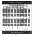
- the connection with the converters is shown in the case of a 6x9 module, where all the long wires have been removed (only series connections).
- the converters are just on one side of the module (hence being non-uniform or non-symmetric), it is known a priori that all groups will have the input and the output at that side of the module.
- the converters are located at the bottom side of the module resulting in a non-symmetric or non-uniform module.
- the bottom and the top side of the module have exactly the same connections between the substrings.
- Substring 3 is connected with substring 4 both at the bottom and at the top of the module.
- wires at the bottom side are used only in the case where a group of at least four substrings is present.
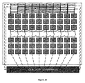
- the number of converters allows all pairs of substrings to be connected with a local converter, some wires from the side of the converters can be removed. Most run-time instantiations will still be realizable in the same way as before, while others will require the use of more converters.
- the location of the local dc/dc converters allows "all" wires to be removed from the top side of the module, enabling all acceptable configurations to be realizable as before (see embodiment of figure 17 ).
- the pruning of wires in these embodiments is a trade-off and not a constraint.
- n is an input, it can potentially be combined, as an input to a converter, with output n+1, n+3, n+5 as well as n-1, n-3, n-5 in a specific run-time instantiation. This applies for all potential inputs of the module.
- each potential input is connected to one converter and all potential outputs are connected to all the converters. This allows all possible combinations of input and output pairs to be connected to a converter.
- Module with an odd number of substrings it was stated before with respect to "selection of the substrings" that priority can be given either in having an even number of substrings, either in having the shortest substrings possible, which means that a module of 6 by 9 can have 9 substrings of 6 cells length.
- the substrings cannot be divided now in two equal sets according to the allowed current flow direction, as one set exceeds the other by one substring.
- the presence of an odd number of substrings indicates also that in a standard all in series connection of the substrings, the input and output of the module will be at different sides of the module. If no long wires are present, it means that one substring (from the larger set of substrings) will always be isolated from any electrical connection.
- At least one long wire should be added. If a long wire is added to connect the output of the last substring to the converters, the majority of the run-time instantiations that are described above can be realized. As the number of substrings is not even now, the number of converters is calculated as: (number of substrings+1)/2. The addition of this long wire, also allows the isolation of a single substring (which allows the same current flow as the last substring) and the connection of the last substring with a converter.
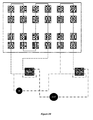
- each "box" of a dc/dc converter includes the diodes necessary to allow parallel connection then all possible connections of the converters (both between the converters and between the converters and the substrings) without the module are shown in the embodiment of figure 20 .
- each potential input is connected to one converter and all potential outputs are connected to all the converters, as mentioned in the previous section.
- the converters can be connected with each other in series or in parallel. As every input is connected to just one converter, it is possible that converter 1 and 3 are in use. For that reason, there is also a wire connecting converters 1 and 3 in series, bypassing converter 2. All inputs of the converters are connected to the general input of the module and all outputs are connected to the general output of the module allowing parallel connection of the converters. All connections are controlled by switches. The connections to the general input and output also allow any set of converters to be in use in series connection.
- each input and output is connected to one converter.
- the out pins of the in ports (which are the same as the in pins of the out ports) of the converters are connected with one another.
- Substrings 1 and 2 can be connected to converter 1, substrings 3 and 4 connected to converter 2 and substrings 5 and 6 connected to converter 3 and the converters can be then connected in any possible way (series, parallel or hybrid). It is also possible to connect substrings 1, 2, 3 and 4 in series with one converter. When the switch between converter 1 and 2 (the black wire) is closed, then the in pin of the first substring is transferred to the out pin of the in port of the second converter and 1 and 4 are connected to the same converters and only two converters are in use (2 and 3). If the groups of substrings "break" the numerical order, parallel connection of the converters is possible.
- one group consists of substring pairs (1,2) and (3,4) which are connected in series and then in parallel.
- the second group is substrings 5 and 6 in series.
- Each group is connected to a local converter.
- the converters which are used are number 2 and 3 and are connected in series (a parallel connection of the converters would also be possible with this grouping of the substrings).
- Substrings 1,2,3 and 4 are connected in series and connected to converter number 2, while substrings 5 and 6 are again connected in series and connected to converter 3. The converters between them are connected in parallel.
- the configuration of the module which was described allows different run-time instantiations to exploit different illumination scenarios in the horizontal direction. If a shadow is moving only in the vertical direction, no run-time instantiation is present to improve the efficiency of the module.
- the shortest dimension of the module to form the substrings in order to have less differentiations of irradiation in the vertical direction and less power loss due to vertical directed shading.
- some flexibility in the vertical direction is required and a vertical split of the substrings is considered.
- the goal of the vertical split embodiments is to have a more adjustable module by dividing the substrings in the vertical direction.
- the concept of the vertical split naturally affects the decision of selecting in which dimension of the module the substrings will be formed.
- the optimal choice, without having the vertical split applied, is to have 10 substrings of 6 cells length.
- An embodiment with a vertical division of the substrings leads to a module which has 20 substrings of 3 cells length.
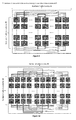
- Each substring of the initial 10 substrings is divided in 2 substrings of 3 cells (see the embodiment of figure 25 ).
- the module now consists of two separate sets (rows) of substrings, the lower and upper set (row). The current flow is indicated by "in” and "out” at the two pins of each substring.
- the module can now be seen as two submodules of 10 by 3. If each set of substrings is treated as a separate module on its own though, the wires required for all the connections described above (in the previous sections) would be twice the amount of the ones used before the vertical split, without even having the submodules or sets of substrings interacting yet. All the wires which would be added contribute to the flexibility of the module to operate under different horizontal irradiation scenarios in which the vertical split is quite unnecessary. When the vertical split is applied, it is hence not useful to keep all the wire connections between the two horizontal submodules so in embodiments with a vertical split it is preferred to prune heavily in those (see below). In contrast, the connections on the top and the bottom of the module (the top of the upper set of substrings and the bottom of the lower set of substrings correspondingly) are left as before, both for the series and parallel cases.
- switches can be added in order to allow all substrings to be connected in series. In the case of uniformity in the vertical direction, these switches are constantly in the closed position, allowing the module to function as a module of 10 substrings. Wires are also added to enable the series connections of all the substrings of the upper and lower set correspondingly. When the upper and lower set of substrings operate under different irradiation conditions, the two sets function independently. In order to allow some flexibility in case of a simultaneous horizontal differentiation of illumination, wires are added to connect all neighboring substrings in each set of substrings. The only interaction of the two sets is the potential connection of each nl substrings with the substring nu.
- the series connections of the module are shown in the embodiment of figure 26 .
- the interaction of the two sets of substrings through parallel connections would lead to an overhead which would not be compensated by the expected gain.
- the only wires which are added in the middle of the module aim at the increase of the flexibility of the module in the horizontal direction, when the vertical split is in use.
- the substrings of each row can potentially be connected in parallel with the nearest substring which allows the same direction of current flow.
- the parallel connections of the module are shown in the embodiment of figure 27 .
- each column is divided in two substrings, leading to 20 substrings of 3 cells.
- a standard module size is considered to be 6 by 9.
- either a division of the module into 6 substrings of 9 cells length or into 9 substrings of 6 cells length has been introduced. If the vertical split is to be applied in an embodiment of the 6 by 9 module, it can be preferable to have a shorter substring length to begin with. If the module is organized to have 9 substrings of 6 cells length, the vertical split would be similar to the one previous described. Each substring would be divided in two substrings of three cells.
- the vertical split is applied to substrings of 9 cells.
- there is a single split of the substrings and the substrings are divided in two substrings of 5 and 4 cells with the same connections between the sets of substrings as described above (see the embodiment of figure 28 ).
- a length of 9 cells means that more irradiation differentiations can be present in that dimension, compared to one of 6 cells.
- a further split of the cells in the vertical direction could hence be applied, leading to three substrings of three cells in each column.
- the module would have three sets of substrings, the upper (u), the middle (m) and the lower (1) set.
- the series and parallel connections in between the sets of substrings would be the same as analyzed in the case of the 10 by 6 module (see the embodiment of figure 29 ).
- the vertical split does not necessary mean that there is a single division by two of the original substrings in embodiments of the present invention. Further divisions can be made if it is necessary or useful.
- a minimum amount of cells in a substring should be assigned though, in order not to have a large overhead due to the additional wires required for all the potential connections.
- a proposed minimum is 2-3 cells per substring.
- the number of local dc/dc converters is computed through the formula (number of substrings)/2. This formula in combination with the absence of long connections and with an even number of substrings means that a single substring cannot be isolated.
- the vertical split is applied to a module of 6 by 10, the result is having 20 substrings.
- the number of local dc/dc converters needed is 10.
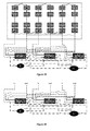
- the converters can either be divided to be situated on both sides of the module, either concentrated on one side of the module.
- the module will function as before the vertical split, using mainly the converters which are situated on the bottom side of the module. For that reason and in order to reduce the overhead, in embodiments of the present invention less converters should be placed on the top side of the module resulting in a non-symmetric or non-uniform module. All input and output pins (which are either at the top or the bottom of the module, not in the middle part) of the substrings are connected to the converters.
- the converter connections are as described in the "Intra-converter connections" section. In the embodiment shown in figure 30 the connections of the module are shown, while the converters are not analytically illustrated.
- the input pins for each converter must be at the same side of the module, as no long wires exist resulting in a non-symmetric or non-uniform module.
- the module can be divided in two by enabling the vertical split and then the two sets of substrings can be treated independently to taking into consideration the differences of horizontal operating conditions. Each set of substrings uses the converters on the corresponding side of the module.
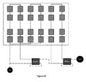
- Another option in such a scenario is to apply the vertical split only at the part of the module which can be affected by vertical irradiation changes, if that is possible. If for example, irradiation changes vertically just at the 4 first columns of the module, then the vertical split can be applied just there, while the other columns of the module (5 to 10) are not divided as the irradiation in the vertical direction is uniform.
- each set of substrings is connected to its "own" converters on one side of the module.
- the result is 3 separate sets of substrings: the upper, the middle and the lower set.
- Each set shares equal number of substrings, but only the substrings which belong either to the upper or lower part of the module have pins on the edge of the module where local converters are potentially located. Placing converters to the middle part would require a much higher technological effort, increased cost and will probably not lead to the desired results. If it considered necessary to have the option of connecting substrings which belong to the middle set of the module with a converter, it is better to add some long wires.
- the substrings in the middle part will directly be connected to the upper part or the lower part of the module. For that reason, the substrings which belong to the middle set of the module are not taken into account whilst computing the total number of substrings of the module.
- the long wires that are shown in the embodiments of figures 31 and 32 are chosen arbitrarily and just indicate how the wires will be placed if the wires connect the pins on the top of the module and the middle of the module correspondingly. Which pins will be connected depends mainly on the cost requirements and on the frequency of each irradiation scenario.
- the dashed wires which are shown in the embodiments of figures 31 and 32 indicate that on that position a switch is present which is not shown.
- the two pins which are used for the in port of the converter can be connected from different sides of the module. This means that if column 1 of the module needs to be removed, the input can be at the bottom of column 10 and the output on the top of column 2.
- the module is divided in two submodules.
- the converters are located at the bottom of the module, long wires are used in order to connect the upper submodule to the converters.
- the long wires connect the converters with the in ant out pins of the upper substrings which are situated at the top side of the module.
- connection are shown in the same shading conditions where converters are located on both sides of the modules.
- converters are located on both sides of the module.
- the first four columns of the module are not likely to be affected by vertical shading, so the vertical split is not applied in that part of the module.
- the rest of the module is divided.
- Three converters are required for this grouping of the substrings, one converter from the top side and two converters from the bottom side resulting in a non-symmetric or non-uniform module. If no converters were placed on the top side of the module, long wires would be needed to connect the upper set of substrings with the converters at the bottom of the module.
- An actively controlled bypass diode is a diode which allows a controllable specific amount of current to flow. In comparison with a normal bypass diode, the current which is bypassed through an actively controlled bypass diode is controllable. From now on, the term bypass /[diode will be used to refer to an actively controlled bypass diode.
- the objective of the proposed topology is, as mentioned earlier, the separation of the module into groups of cells which produce either the same amount of current or voltage (series and parallel connections).
- the run-time variable (“knob-controlled") topology which was described above, the smaller component of the module which can be selected to belong or not to a specific group is a substring and not a single solar cell.
- a substring preferably has to belong to a group of at least two substrings.
- these cells affect the operation of at least one more substring.
- a bypass diode is placed in parallel with those cells, the excess current will flow through the diode, allowing the rest of the cells to produce their maximum power. It is evident that there are several potential positions where bypass diodes can be placed on the module. In principle, diodes could potentially connect any two cells of the module, but it is not cost effective to have a diode connecting two cells where an especially long wire or crossing of other wires is required.
- Figure 37 shows all possible hybrids available in the complete parameterized topology.
- Embodiments of the present invention provide templates that have been illustrated and can be combined in order to have different real physical configurations, which allows more flexibility.
- the concept of the flexible/hybrid series or parallel substring connections, the placement of the local dc/dc converters, the vertical split options, and the active controlled bypass diodes can be combined in a very flexible way to increase the overall efficiency of the module. It is important to include the constraints propagated in a uni-directional way between these different options while combining them.
- design method can be implemented on a computer by providing software, e.g. as module that when run on a computer that allows planning and/or designing a PV module.
- the software is adapted such that when run on a computer it allows selecting or determining of a combination of features of the present invention, e.g. the best approach to optimise cost, efficiency and flexibility.
- the computer system can comprise an expert system set up to propose a design automatically given input constraints.
- the computer can comprise a processor and a memory which stores machine-readable instructions (software as described above) which, when executed by the processor cause the processor to perform the described methods.
- the computer may be implemented as a general purpose computer, e.g. a UNIX workstation or a personal computer.
- the computer typically includes a Central Processing Unit (“CPU”), such as a conventional microprocessor of which a Pentium processor supplied by Intel Corp. USA is only an example, and a number of other units interconnected via bus system.
- the bus system may be any suitable bus system.
- the computer includes at least one memory.
- Memory may include any of a variety of data storage devices known to the skilled person such as random-access memory (“RAM”), read-only memory (“ROM”), and non-volatile read/write memory such as a hard disc as known to the skilled person.
- the computer may further include random-access memory (“RAM”), read-only memory (“ROM”), as well as a display adapter for connecting the system bus to a video display terminal, and an optional input/output (I/O) adapter for connecting peripheral devices (e.g., disk and tape drives) to the system bus.
- RAM random-access memory
- ROM read-only memory
- I/O input/output
- the video display terminal can be the visual output of computer, and can be any suitable display device such as a CRT-based video display well-known in the art of computer hardware. However, with a desk-top computer, a portable or a notebook-based computer, the video display terminal can be replaced with a LCD-based or a gas plasma-based flat panel display.
- the computer further includes an user interface adapter for connecting a keyboard, mouse, and optional speaker.
- the computer can also include a graphical user interface that resides within machine-readable media to direct the operation of the computer.
- Any suitable machine-readable media may retain the graphical user interface, such as a random access memory (RAM), a read-only memory (ROM), a magnetic diskette, magnetic tape, or optical disk (the last three being located in disk and tape drives).
- Any suitable operating system and associated graphical user interface e.g., Microsoft Windows, Linux
- computer includes a control program that resides within computer memory storage. Control program contains instructions that when executed on CPU allow the computer to carry out the operations described with respect to any of the methods of the present invention.
- the graphical user interface is used to visualize the PV module as it is being developed. It can also be used for planning and/or designing and can be adapted to simulate run-time operation of the module under varying lighting conditions, e.g for visualising qualitative and/or quantitative feedback about the effect of the planned/simulated PV module and it can also be used for visualizing the selecting or determining of an approach or the best approach for the design.
- peripheral devices such as optical disk media, audio adapters, or chip programming devices, such as PAL or EPROM programming devices well-known in the art of computer hardware, and the like may be utilized in addition to or in place of the hardware already described.
- the computer program product for carrying out the method of the present invention can reside in any suitable memory and the present invention applies equally regardless of the particular type of signal bearing media used to actually store the computer program product.
- Examples of computer readable signal bearing media include: recordable type media such as floppy disks and CD ROMs, solid state memories, tape storage devices, magnetic disks.
- the present invention also includes a software product which when executed on a suitable computing device carries out any of the methods of the present invention.
- Suitable software can be obtained by programming in a suitable high level language such as C and compiling on a suitable compiler for the target computer processor.
Priority Applications (5)
| Application Number | Priority Date | Filing Date | Title |
|---|---|---|---|
| EP20110186415 EP2587334A1 (fr) | 2011-10-24 | 2011-10-24 | Configuration PV reconfigurable |
| EP12778065.8A EP2771753B1 (fr) | 2011-10-24 | 2012-10-05 | Configuration photovoltaïque reconfigurable |
| PCT/EP2012/069727 WO2013060564A2 (fr) | 2011-10-24 | 2012-10-05 | Configuration photovoltaïque reconfigurable |
| JP2014536179A JP6389435B2 (ja) | 2011-10-24 | 2012-10-05 | 再構成可能なpv構成 |
| US14/354,012 US10386878B2 (en) | 2011-10-24 | 2012-10-05 | Reconfigurable PV Configuration |
Applications Claiming Priority (1)
| Application Number | Priority Date | Filing Date | Title |
|---|---|---|---|
| EP20110186415 EP2587334A1 (fr) | 2011-10-24 | 2011-10-24 | Configuration PV reconfigurable |
Publications (1)
| Publication Number | Publication Date |
|---|---|
| EP2587334A1 true EP2587334A1 (fr) | 2013-05-01 |
Family
ID=45491233
Family Applications (2)
| Application Number | Title | Priority Date | Filing Date |
|---|---|---|---|
| EP20110186415 Withdrawn EP2587334A1 (fr) | 2011-10-24 | 2011-10-24 | Configuration PV reconfigurable |
| EP12778065.8A Active EP2771753B1 (fr) | 2011-10-24 | 2012-10-05 | Configuration photovoltaïque reconfigurable |
Family Applications After (1)
| Application Number | Title | Priority Date | Filing Date |
|---|---|---|---|
| EP12778065.8A Active EP2771753B1 (fr) | 2011-10-24 | 2012-10-05 | Configuration photovoltaïque reconfigurable |
Country Status (4)
| Country | Link |
|---|---|
| US (1) | US10386878B2 (fr) |
| EP (2) | EP2587334A1 (fr) |
| JP (1) | JP6389435B2 (fr) |
| WO (1) | WO2013060564A2 (fr) |
Cited By (4)
| Publication number | Priority date | Publication date | Assignee | Title |
|---|---|---|---|---|
| US20150131187A1 (en) * | 2013-11-08 | 2015-05-14 | The Board Of Trustees Of The University Of Illinois | Systems and Methods for Photovoltaic String Protection |
| WO2016042480A1 (fr) * | 2014-09-19 | 2016-03-24 | Alteneiji Hamad Musabeh Ahmed Saif | Module photovoltaïque dynamique et procédé de fabrication |
| CN105634041A (zh) * | 2014-10-31 | 2016-06-01 | 中国科学院声学研究所 | 一种电池网络管理方法 |
| US20170077869A1 (en) * | 2015-09-12 | 2017-03-16 | Imec Vzw | Reconfigurable Photovoltaic Module |
Families Citing this family (22)
| Publication number | Priority date | Publication date | Assignee | Title |
|---|---|---|---|---|
| CN102640297B (zh) * | 2010-02-26 | 2015-01-14 | 株式会社东芝 | 异常诊断装置和异常诊断方法 |
| US9791878B2 (en) * | 2012-08-02 | 2017-10-17 | King Kuen Hau | Digital voltage controller |
| WO2015077534A1 (fr) * | 2013-11-22 | 2015-05-28 | Massachusetts Institute Of Technology | Équilibrage de puissance photovoltaïque et traitement de puissance différentielle |
| WO2015175923A1 (fr) * | 2014-05-16 | 2015-11-19 | HST Solar Farms, Inc. | Systèmes et procédés permettant une ingénierie de réseau photovoltaïque solaire |
| CN106605304B (zh) * | 2014-08-28 | 2019-02-22 | 松下知识产权经营株式会社 | 太阳能电池组件和太阳能电池组件的制造方法 |
| US10097005B2 (en) | 2015-08-17 | 2018-10-09 | Solarcity Corporation | Self-configuring photo-voltaic panels |
| US10270254B2 (en) * | 2015-08-17 | 2019-04-23 | Solarcity Corporation | Energy generation interconnection |
| US11241799B2 (en) * | 2016-03-18 | 2022-02-08 | Intelli-Products Inc. | Solar energy array robotic assembly |
| CN106251746B (zh) * | 2016-08-22 | 2022-04-29 | 杭州澳宇自动化设备有限公司 | 一种便携式光伏电站模拟仪运行控制系统 |
| CN106787729B (zh) * | 2017-02-08 | 2023-05-30 | 广西大学 | 一种局部阴影下提高光伏阵列输出效率的控制系统及方法 |
| JP2019050350A (ja) * | 2017-06-12 | 2019-03-28 | ザ・ボーイング・カンパニーThe Boeing Company | 変更可能なストリング長を有するソーラーセルアレイ |
| CN107395115B (zh) * | 2017-07-03 | 2019-10-22 | 南京航空航天大学 | 激光照射下光伏阵列背板热电阵列连接架构的确定方法 |
| CN107528340B (zh) * | 2017-07-28 | 2020-09-25 | 华为数字技术(苏州)有限公司 | 一种光伏发电的控制方法及光伏发电系统 |
| KR101803056B1 (ko) * | 2017-08-25 | 2017-11-29 | (주)대연씨앤아이 | 태양광 발전 모니터링 시스템을 위한 오류 보정 시스템 및 방법 |
| US10819270B2 (en) * | 2018-03-16 | 2020-10-27 | Uchicago Argonne, Llc | High temperature selective emitters via critical coupling of weak absorbers |
| JP2020181905A (ja) * | 2019-04-25 | 2020-11-05 | シャープ株式会社 | 太陽電池モジュール |
| EP3772757A1 (fr) * | 2019-08-07 | 2021-02-10 | Solaredge Technologies Ltd. | Agencement de panneau solaire |
| CN110829427B (zh) * | 2019-11-26 | 2023-09-26 | 远景智能国际私人投资有限公司 | 光伏组件的接串方法、装置、设备及存储介质 |
| IT202000000484A1 (it) * | 2020-01-13 | 2021-07-13 | Alfredo Chiacchieroni | Modulo fotovoltaico e relativo procedimento di fabbricazione |
| KR102458450B1 (ko) * | 2020-12-01 | 2022-10-25 | 한국공학대학교산학협력단 | 태양광 발전 시스템 효율 향상을 위한 태양 전지 모듈 최적 결선 방법 및 태양 전지 모듈 최적 결선 방법 제공 장치 |
| CN113078241B (zh) * | 2021-03-31 | 2022-06-28 | 上海空间电源研究所 | 一种空间太阳电池阵及其混联方法 |
| CN114864726B (zh) * | 2022-07-06 | 2022-09-23 | 一道新能源科技(衢州)有限公司 | 一种制造叠瓦组件的方法 |
Citations (4)
| Publication number | Priority date | Publication date | Assignee | Title |
|---|---|---|---|---|
| WO2005112551A2 (fr) | 2004-05-21 | 2005-12-01 | Hansung Engineering Co. Ltd | Procede de compensation d'une ombre partielle dans un systeme d'energie photovoltaique |
| US20090079412A1 (en) | 2007-09-24 | 2009-03-26 | Yao Hsien Kuo | Apparatus and method for controlling the output of a photovoltaic array |
| WO2010070621A1 (fr) * | 2008-12-18 | 2010-06-24 | Centre National De La Recherche Scientifique | Systeme de gestion electronique de cellules photovoltaiques |
| US20100198424A1 (en) * | 2009-01-30 | 2010-08-05 | Toru Takehara | Method for reconfigurably connecting photovoltaic panels in a photovoltaic array |
Family Cites Families (17)
| Publication number | Priority date | Publication date | Assignee | Title |
|---|---|---|---|---|
| US4175249A (en) * | 1978-06-19 | 1979-11-20 | The United States Of America As Represented By The Administrator Of The National Aeronautics And Space Administration | Self-reconfiguring solar cell system |
| US6350944B1 (en) * | 2000-05-30 | 2002-02-26 | Hughes Electronics Corporation | Solar module array with reconfigurable tile |
| US7510640B2 (en) * | 2004-02-18 | 2009-03-31 | General Motors Corporation | Method and apparatus for hydrogen generation |
| JP2010080548A (ja) * | 2008-09-24 | 2010-04-08 | Sekisui Chem Co Ltd | 太陽光発電モジュール |
| US8273979B2 (en) * | 2008-10-15 | 2012-09-25 | Xandex, Inc. | Time averaged modulated diode apparatus for photovoltaic application |
| US8115340B2 (en) * | 2008-12-12 | 2012-02-14 | Paceco Corp. | System for controlling power from a photovoltaic array by selectively configurating connections between photovoltaic panels |
| US20100301676A1 (en) * | 2009-05-28 | 2010-12-02 | General Electric Company | Solar power generation system including weatherable units including photovoltaic modules and isolated power converters |
| EP2280469B1 (fr) * | 2009-07-30 | 2016-07-06 | Nxp B.V. | Unité photovoltaïque, son convertisseur cc/cc, et son procédé de fonctionnement |
| KR101097260B1 (ko) * | 2009-12-15 | 2011-12-22 | 삼성에스디아이 주식회사 | 계통 연계형 전력 저장 시스템 및 전력 저장 시스템 제어 방법 |
| US20110139184A1 (en) * | 2009-12-16 | 2011-06-16 | Nagendra Srinivas Cherukupalli | Systems, Circuits, and Methods for an Intelligent Cleaning System for an Adaptive Solar Power System |
| DE102010017746A1 (de) * | 2010-05-03 | 2011-11-03 | Sma Solar Technology Ag | Verfahren zur Begrenzung der Generatorspannung einer photovoltaischen Anlage im Gefahrenfall und photovoltaische Anlage |
| WO2012038828A1 (fr) * | 2010-09-23 | 2012-03-29 | Hybridine Power Electronics Inc. | Procédé et système pour optimiser l'énergie produite par un système photovoltaïque |
| WO2012048307A1 (fr) * | 2010-10-09 | 2012-04-12 | Sager Brian M | Panneau solaire doté d'interconnexions reconfigurables |
| US9136710B1 (en) * | 2011-03-08 | 2015-09-15 | Sunpower Corporation | Multi-path converters for PV substrings |
| US8829715B2 (en) * | 2011-04-29 | 2014-09-09 | General Electric Company | Switching coordination of distributed dc-dc converters for highly efficient photovoltaic power plants |
| US9252294B2 (en) * | 2011-06-08 | 2016-02-02 | Andrew V. Latham | Instantaneous solar array recombining technology |
| US8970065B2 (en) * | 2011-08-04 | 2015-03-03 | Eaton Corporation | System and method for increasing voltage in a photovoltaic inverter |
-
2011
- 2011-10-24 EP EP20110186415 patent/EP2587334A1/fr not_active Withdrawn
-
2012
- 2012-10-05 US US14/354,012 patent/US10386878B2/en active Active
- 2012-10-05 WO PCT/EP2012/069727 patent/WO2013060564A2/fr active Application Filing
- 2012-10-05 EP EP12778065.8A patent/EP2771753B1/fr active Active
- 2012-10-05 JP JP2014536179A patent/JP6389435B2/ja not_active Expired - Fee Related
Patent Citations (4)
| Publication number | Priority date | Publication date | Assignee | Title |
|---|---|---|---|---|
| WO2005112551A2 (fr) | 2004-05-21 | 2005-12-01 | Hansung Engineering Co. Ltd | Procede de compensation d'une ombre partielle dans un systeme d'energie photovoltaique |
| US20090079412A1 (en) | 2007-09-24 | 2009-03-26 | Yao Hsien Kuo | Apparatus and method for controlling the output of a photovoltaic array |
| WO2010070621A1 (fr) * | 2008-12-18 | 2010-06-24 | Centre National De La Recherche Scientifique | Systeme de gestion electronique de cellules photovoltaiques |
| US20100198424A1 (en) * | 2009-01-30 | 2010-08-05 | Toru Takehara | Method for reconfigurably connecting photovoltaic panels in a photovoltaic array |
Non-Patent Citations (1)
| Title |
|---|
| VELASCO G ET AL: "Grid-connected PV systems energy extraction improvement by means of an Electric Array Reconfiguration (EAR) strategy: Operating principle and experimental results", POWER ELECTRONICS SPECIALISTS CONFERENCE, 2008. PESC 2008. IEEE, IEEE, PISCATAWAY, NJ, USA, 15 June 2008 (2008-06-15), pages 1983 - 1988, XP031300257, ISBN: 978-1-4244-1667-7 * |
Cited By (7)
| Publication number | Priority date | Publication date | Assignee | Title |
|---|---|---|---|---|
| US20150131187A1 (en) * | 2013-11-08 | 2015-05-14 | The Board Of Trustees Of The University Of Illinois | Systems and Methods for Photovoltaic String Protection |
| US9799779B2 (en) * | 2013-11-08 | 2017-10-24 | The Board Of Trustees Of The University Of Illinois | Systems and methods for photovoltaic string protection |
| WO2016042480A1 (fr) * | 2014-09-19 | 2016-03-24 | Alteneiji Hamad Musabeh Ahmed Saif | Module photovoltaïque dynamique et procédé de fabrication |
| CN105634041A (zh) * | 2014-10-31 | 2016-06-01 | 中国科学院声学研究所 | 一种电池网络管理方法 |
| CN105634041B (zh) * | 2014-10-31 | 2017-12-01 | 中国科学院声学研究所 | 一种电池网络管理方法 |
| US20170077869A1 (en) * | 2015-09-12 | 2017-03-16 | Imec Vzw | Reconfigurable Photovoltaic Module |
| US10651787B2 (en) * | 2015-09-12 | 2020-05-12 | Imec Vzw | Reconfigurable photovoltaic module |
Also Published As
| Publication number | Publication date |
|---|---|
| WO2013060564A2 (fr) | 2013-05-02 |
| US20140312700A1 (en) | 2014-10-23 |
| WO2013060564A3 (fr) | 2013-07-18 |
| US10386878B2 (en) | 2019-08-20 |
| JP6389435B2 (ja) | 2018-09-12 |
| EP2771753A2 (fr) | 2014-09-03 |
| JP2014533072A (ja) | 2014-12-08 |
| EP2771753B1 (fr) | 2020-05-06 |
Similar Documents
| Publication | Publication Date | Title |
|---|---|---|
| EP2771753B1 (fr) | Configuration photovoltaïque reconfigurable | |
| Krishna et al. | Optimal SuDoKu reconfiguration technique for total-cross-tied PV array to increase power output under non-uniform irradiance | |
| Malathy et al. | Reconfiguration strategies to extract maximum power from photovoltaic array under partially shaded conditions | |
| Krishna et al. | Reconfiguration strategies for reducing partial shading effects in photovoltaic arrays: State of the art | |
| US10651787B2 (en) | Reconfigurable photovoltaic module | |
| Pareek et al. | Enhanced power generation of partial shaded photovoltaic fields by forecasting the interconnection of modules | |
| Belhaouas et al. | PV array power output maximization under partial shading using new shifted PV array arrangements | |
| Patnaik et al. | Reconfiguration strategy for optimization of solar photovoltaic array under non-uniform illumination conditions | |
| Khan et al. | Review and qualitative analysis of submodule-level distributed power electronic solutions in PV power systems | |
| Pareek et al. | Optimal interconnections to address partial shading losses in solar photovoltaic arrays | |
| JP5480287B2 (ja) | 太陽電池パネル間の接続を選択的に構成することにより太陽電池アレイからの電力を制御するシステム | |
| US10097005B2 (en) | Self-configuring photo-voltaic panels | |
| EP2891187A2 (fr) | Système photovoltaïque reconfigurable dynamiquement | |
| Mehedi et al. | Critical evaluation and review of partial shading mitigation methods for grid-connected PV system using hardware solutions: The module-level and array-level approaches | |
| US11894802B2 (en) | Solar module racking system | |
| Zhu et al. | Optimal photovoltaic array dynamic reconfiguration strategy based on direct power evaluation | |
| Yang et al. | Improved non-symmetrical puzzle reconfiguration scheme for power loss reduction in photovoltaic systems under partial shading conditions | |
| Amar Raj et al. | A novel solar photovoltaic array reconfiguration technique using two-dimensional generalized Arnold's cat map | |
| US10270254B2 (en) | Energy generation interconnection | |
| Fathy et al. | An enhanced reconfiguration approach for mitigating the shading effect on photovoltaic array using honey badger algorithm | |
| Rajani et al. | An automatic column wiring resistance algorithm for static reconfiguration of PV arrays and analysis of reconfigured TCT and TTCL under dynamic shading conditions | |
| US20180089339A1 (en) | Photovoltaic Installation Design Systems | |
| Merino et al. | Optimization of energy distribution in solar panel array configurations by graphs and Minkowski’s paths | |
| Baka et al. | Near-static shading exploration for smart photovoltaic module topologies based on snake-like configurations | |
| Gautam et al. | A Review on Various Mathematical Based Static Reconfiguration Strategies to Improve Generated Power under Partial Shading Conditions |
Legal Events
| Date | Code | Title | Description |
|---|---|---|---|
| PUAI | Public reference made under article 153(3) epc to a published international application that has entered the european phase |
Free format text: ORIGINAL CODE: 0009012 |
|
| AK | Designated contracting states |
Kind code of ref document: A1 Designated state(s): AL AT BE BG CH CY CZ DE DK EE ES FI FR GB GR HR HU IE IS IT LI LT LU LV MC MK MT NL NO PL PT RO RS SE SI SK SM TR |
|
| AX | Request for extension of the european patent |
Extension state: BA ME |
|
| STAA | Information on the status of an ep patent application or granted ep patent |
Free format text: STATUS: THE APPLICATION IS DEEMED TO BE WITHDRAWN |
|
| 18D | Application deemed to be withdrawn |
Effective date: 20131105 |