EP0955485B1 - Drehschwingungsdämpfer bzw. drehelastische und schwingungsdämpfende Kupplung - Google Patents
Drehschwingungsdämpfer bzw. drehelastische und schwingungsdämpfende Kupplung Download PDFInfo
- Publication number
- EP0955485B1 EP0955485B1 EP99890101A EP99890101A EP0955485B1 EP 0955485 B1 EP0955485 B1 EP 0955485B1 EP 99890101 A EP99890101 A EP 99890101A EP 99890101 A EP99890101 A EP 99890101A EP 0955485 B1 EP0955485 B1 EP 0955485B1
- Authority
- EP
- European Patent Office
- Prior art keywords
- inner part
- subdivisions
- fixed
- damper
- spring elements
- Prior art date
- Legal status (The legal status is an assumption and is not a legal conclusion. Google has not performed a legal analysis and makes no representation as to the accuracy of the status listed.)
- Expired - Lifetime
Links
Images

Classifications
-
- F—MECHANICAL ENGINEERING; LIGHTING; HEATING; WEAPONS; BLASTING
- F16—ENGINEERING ELEMENTS AND UNITS; GENERAL MEASURES FOR PRODUCING AND MAINTAINING EFFECTIVE FUNCTIONING OF MACHINES OR INSTALLATIONS; THERMAL INSULATION IN GENERAL
- F16F—SPRINGS; SHOCK-ABSORBERS; MEANS FOR DAMPING VIBRATION
- F16F15/00—Suppression of vibrations in systems; Means or arrangements for avoiding or reducing out-of-balance forces, e.g. due to motion
- F16F15/10—Suppression of vibrations in rotating systems by making use of members moving with the system
- F16F15/12—Suppression of vibrations in rotating systems by making use of members moving with the system using elastic members or friction-damping members, e.g. between a rotating shaft and a gyratory mass mounted thereon
- F16F15/131—Suppression of vibrations in rotating systems by making use of members moving with the system using elastic members or friction-damping members, e.g. between a rotating shaft and a gyratory mass mounted thereon the rotating system comprising two or more gyratory masses
- F16F15/133—Suppression of vibrations in rotating systems by making use of members moving with the system using elastic members or friction-damping members, e.g. between a rotating shaft and a gyratory mass mounted thereon the rotating system comprising two or more gyratory masses using springs as elastic members, e.g. metallic springs
- F16F15/1336—Leaf springs, e.g. radially extending
-
- F—MECHANICAL ENGINEERING; LIGHTING; HEATING; WEAPONS; BLASTING
- F16—ENGINEERING ELEMENTS AND UNITS; GENERAL MEASURES FOR PRODUCING AND MAINTAINING EFFECTIVE FUNCTIONING OF MACHINES OR INSTALLATIONS; THERMAL INSULATION IN GENERAL
- F16D—COUPLINGS FOR TRANSMITTING ROTATION; CLUTCHES; BRAKES
- F16D3/00—Yielding couplings, i.e. with means permitting movement between the connected parts during the drive
- F16D3/50—Yielding couplings, i.e. with means permitting movement between the connected parts during the drive with the coupling parts connected by one or more intermediate members
- F16D3/56—Yielding couplings, i.e. with means permitting movement between the connected parts during the drive with the coupling parts connected by one or more intermediate members comprising elastic metal lamellae, elastic rods, or the like, e.g. arranged radially or parallel to the axis, the members being shear-loaded collectively by the total load
-
- F—MECHANICAL ENGINEERING; LIGHTING; HEATING; WEAPONS; BLASTING
- F16—ENGINEERING ELEMENTS AND UNITS; GENERAL MEASURES FOR PRODUCING AND MAINTAINING EFFECTIVE FUNCTIONING OF MACHINES OR INSTALLATIONS; THERMAL INSULATION IN GENERAL
- F16F—SPRINGS; SHOCK-ABSORBERS; MEANS FOR DAMPING VIBRATION
- F16F15/00—Suppression of vibrations in systems; Means or arrangements for avoiding or reducing out-of-balance forces, e.g. due to motion
- F16F15/10—Suppression of vibrations in rotating systems by making use of members moving with the system
- F16F15/12—Suppression of vibrations in rotating systems by making use of members moving with the system using elastic members or friction-damping members, e.g. between a rotating shaft and a gyratory mass mounted thereon
- F16F15/121—Suppression of vibrations in rotating systems by making use of members moving with the system using elastic members or friction-damping members, e.g. between a rotating shaft and a gyratory mass mounted thereon using springs as elastic members, e.g. metallic springs
- F16F15/1215—Leaf springs, e.g. radially extending
-
- F—MECHANICAL ENGINEERING; LIGHTING; HEATING; WEAPONS; BLASTING
- F16—ENGINEERING ELEMENTS AND UNITS; GENERAL MEASURES FOR PRODUCING AND MAINTAINING EFFECTIVE FUNCTIONING OF MACHINES OR INSTALLATIONS; THERMAL INSULATION IN GENERAL
- F16F—SPRINGS; SHOCK-ABSORBERS; MEANS FOR DAMPING VIBRATION
- F16F15/00—Suppression of vibrations in systems; Means or arrangements for avoiding or reducing out-of-balance forces, e.g. due to motion
- F16F15/10—Suppression of vibrations in rotating systems by making use of members moving with the system
- F16F15/16—Suppression of vibrations in rotating systems by making use of members moving with the system using a fluid or pasty material
Definitions
- the invention relates to a known torsional vibration damper or torsionally elastic and vibration-damping coupling with between an inner part and an outer part used radial spring elements for torque transmission and liquid-filled communicating with one another via throttle gaps Damping chambers, the spring elements at one end in Outer part are clamped between spacers and other in axial grooves of the inner part and the chambers on the one hand through the spring elements, on the other hand through additional radial gaps that leave the throttle gap free Subdivisions between adjacent spring elements separated from each other are.
- the spring elements serve, for example Spring leaves or spring packs, for torque transmission and enable at the same time an influence due to their resilient properties the torsional vibrations that occur. Due to the elasticity of the Spring elements also occur during the torque transmission Relative rotation between the inner and outer part and thus to a liquid displacement between the neighboring liquid-filled chambers, which leads to a flow through the throttle gap and thus to a hydraulic Damping leads.
- the inner part is dimensioned quite small in diameter, which makes the Connection of the inner part when integrating the damper or the clutch in a drive train requires an external, enlarged connection flange, radial sufficient for the required torque transmission To achieve screw spacing, which connecting flanges take up the entire space enlarge the damper or the couplings accordingly.
- the invention is therefore based on the object of a damper or To create coupling of the type described, which or at Low susceptibility to cavitation due to favorable connection options during installation features in a drive train and a compact design.
- the invention solves this problem in that the subdivisions the inner part belong to each and each from a base projecting between the axial grooves and a subsequent one, leaving the end throttle gap free to the opposite spacer extending divider exist, with holes in the base for the use of connecting screws are provided.
- the throttle gaps are moved radially outwards, so that the rotation Damping fluid displaced into the outer peripheral area a reduction the risk of cavitation in the throttling gaps.
- the divisions can be made in one piece with the inner part, it is but it is quite possible that the subdivisions consist of one on the inner part hub molded pre-arched base and its own, on an inner part fixed Assemble the end plate attached divider, which despite the Multi-part construction sufficient space for the arrangement of the screw holes offers in the base area.
- the subdivisions can also be used prepare as separate components. So the subdivisions can be made consist of individual separating blocks attached to an end plate fixed to the inner part, which are lined up along the outer peripheral surface of the inner part hub and form the axial grooves or the subdivisions between their base can come from their own base and their own Assemble a separator fixed to the inner part of the end plate, whereby the foot lugs provided as a sleeve form the axial grooves between them and are clamped between end plates fixed to the inner part.
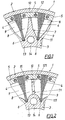
- a torsionally flexible and vibration-damping coupling 1 has an outer part 2, an inner part 3 and radial inserted between the outer part and the inner part Spring elements 4 for torque transmission, which spring elements 4 are clamped at one end in the outer part 2 between intermediate pieces 5 and engage at the other end in axial grooves 6 of the inner part 3.
- For vibration damping is also the cavity between the outer part 2 and inner part 3 on the one hand by the radial spring elements 4, on the other hand by additional radial subdivisions 7 divided into individual chambers 8, 9 between the spring elements 4, which chambers 8, 9 in the area of the subdivisions 7 via throttle gaps 10 communicate with each other, so that due to torsional vibrations relative rotations the damping fluid from the inner and outer part one chambers are displaced into the neighboring chambers and open it up Due to the flow through the throttle gap 10 for hydraulic damping comes.
- the subdivisions 7 belong to the inner part 3 and each consist of a base 11 protruding between the axial grooves 6 and a subsequent, radially outwards to the opposite intermediate pieces 5 extending dividing web 12, one between the one in plan Annular sector corresponding spacers 5 and the free end of the Separators 12, the throttle column 10 arise.
- the from the inner part hub 13 radially outwardly projecting foot lugs 11 now offer sufficient space for Arrangement of holes 14 for connecting screws so that the coupling 1 on the inside directly via these connection screws 14 into a drive train can be integrated without own external Connection flange.
- the subdivisions 7 are in one piece and molded directly onto the inner part 3, from manufacturing technology
- the subdivisions can also be partially or entirely for reasons own components exist.
- the subdivisions 71 are pieced together, wherein only the bulging foot lug 111 is molded onto the inner part hub 13 is and the separator 121, however, as a separate component on the base 111, which separating web 121 connects to an end plate 15 fixed to the inner part is attached.
- 3 are the subdivisions 72 prefabricated as dividing blocks 122, which along the outer peripheral surface of the Inner part hub 13 lined up and with screws 16 on an inner part fixed End plate 15 are attached.
- the foot lugs 112 of these dividing blocks 122 in turn have the holes 14 for connecting screws and form between them the axial grooves 6 for spring engagement.
- the subdivisions 73 are set in each case from its own base, provided as sleeve 113, and its own Separator 123 together, the separators on an inner part fixed end plate 15 attached and the sleeves 113 between two inner part fixed end plates 15 are clamped.
- the sleeves 113 in turn form the axial grooves between them 6 for spring engagement and serve themselves as holes 14 for the connecting screws.
Landscapes
- Engineering & Computer Science (AREA)
- General Engineering & Computer Science (AREA)
- Mechanical Engineering (AREA)
- Physics & Mathematics (AREA)
- Acoustics & Sound (AREA)
- Aviation & Aerospace Engineering (AREA)
- Mechanical Operated Clutches (AREA)
Description
- Fig. 1, 2, 3 und 4
- jeweils einen Ausschnitt aus vier verschiedenen Ausführungsbeispielen einer erfindungsgemäßen Kupplung im Querschnitt.
Claims (5)
- Drehschwingungsdämpfer bzw. drehelastische und schwingungsdämpfende Kupplung (1) mit zwischen einem Innenteil (3) und einem Außenteil (2) eingesetzten radialen Federelementen (4) zur Drehmomentübertragung und über Drosselspalte (10) miteinander in Verbindung stehenden flüssigkeitsgefüllten Kammern (8, 9) zur Dämpfung, wobei die Federelemente (4) einerends im Außenteil (2) zwischen Zwischenstücken (5) eingespannt sind und andernends in Axialnuten (6) des Innenteils (3) eingreifen und die Kammern (8, 9) einerseits durch die Federelemente (4), anderseits durch zusätzliche, die Drosselspalte (10) freilassende radiale Unterteilungen (7) zwischen benachbarten Federelementen (4) voneinander getrennt sind, dadurch gekennzeichnet, daß die Unterteilungen (7, 71, 72, 73) dem Innenteil (3) zugehören und jeweils aus einem zwischen den Axialnuten (6) hochragenden Fußansatz (11, 111, 112, 113) und einem anschließenden, sich unter Freilassung des endseitigen Drosselspaltes (10) bis zum gegenüberliegenden Zwischenstück (5) erstreckenden Trennsteg (12, 121, 123) bestehen, wobei in den Fußansätzen (11, 111, 112, 113) Bohrungen (14) zum Einsatz von Anschlußschrauben vorgesehen sind.
- Dämpfer bzw. Kupplung nach Anspruch 1, dadurch gekennzeichnet, daß die Zwischenstücke (5) einen im wesentlichen einem Sektor eines Kreisringes entsprechenden Grundriß aufweisen und sich die Trennstege (12, 121, 123) der Unterteilungen (7, 71, 72, 73) bis zum Innenbogen der Zwischenstücke (5) erstrecken.
- Dämpfer bzw. Kupplung nach Anspruch 1 oder 2, dadurch gekennzeichnet, daß sich die Unterteilungen (71) aus einem an der Innenteilnabe (13) angeformten vorgewölbten Fußansatz (111) und einem eigenen, an einer innenteilfesten Stirnplatte (15) befestigten Trennsteg (121) zusammensetzen.
- Dämpfer bzw. Kupplung nach Anspruch 1 oder 2, dadurch gekennzeichnet, daß die Unterteilungen (72) aus einzelnen, an einer innenteilfesten Stirnplatte (15) befestigten Trennklötzen (122) bestehen, die entlang der Außenumfangsfläche der Innenteilnabe (13) nebeneinandergereiht sind und zwischen ihren Fußansätzen (112) die Axialnuten (6) bilden.
- Dämpfer bzw. Kupplung nach Anspruch 1 oder 2, dadurch gekennzeichnet, daß sich die Unterteilungen (73) aus einem eigenen Fußansatz (113) und einem eigenen, an einer innenteilfesten Stirnplatte (15) befestigten Trennsteg (123) zusammensetzen, wobei die als Hülsen vorgesehenen Fußansätze (113) zwischen sich die Axialnuten (6) bilden und zwischen innenteilfesten Stirnplatten (15) eingespannt sind.
Applications Claiming Priority (2)
| Application Number | Priority Date | Filing Date | Title |
|---|---|---|---|
| AT77798 | 1998-05-08 | ||
| AT0077798A AT406293B (de) | 1998-05-08 | 1998-05-08 | Drehschwingungsdämpfer bzw. drehelastische und schwingungsdämpfende kupplung |
Publications (3)
| Publication Number | Publication Date |
|---|---|
| EP0955485A2 EP0955485A2 (de) | 1999-11-10 |
| EP0955485A3 EP0955485A3 (de) | 2002-02-13 |
| EP0955485B1 true EP0955485B1 (de) | 2004-09-22 |
Family
ID=3499490
Family Applications (1)
| Application Number | Title | Priority Date | Filing Date |
|---|---|---|---|
| EP99890101A Expired - Lifetime EP0955485B1 (de) | 1998-05-08 | 1999-03-24 | Drehschwingungsdämpfer bzw. drehelastische und schwingungsdämpfende Kupplung |
Country Status (5)
| Country | Link |
|---|---|
| US (1) | US6176785B1 (de) |
| EP (1) | EP0955485B1 (de) |
| JP (1) | JP2000035055A (de) |
| AT (1) | AT406293B (de) |
| DE (1) | DE59910558D1 (de) |
Families Citing this family (13)
| Publication number | Priority date | Publication date | Assignee | Title |
|---|---|---|---|---|
| DE19950597A1 (de) * | 1999-10-21 | 2001-04-26 | Mannesmann Sachs Ag | Antriebsanordnung |
| JP3707072B2 (ja) * | 2001-01-05 | 2005-10-19 | 石川島播磨重工業株式会社 | ガスタービン発電設備 |
| KR100412390B1 (ko) * | 2001-09-21 | 2003-12-31 | 현대자동차주식회사 | 댐퍼클러치 |
| DE102005009446A1 (de) * | 2005-03-02 | 2006-09-14 | Mtu Friedrichshafen Gmbh | Antriebseinheit für ein Hybridfahrzeug |
| JP4954634B2 (ja) * | 2006-08-07 | 2012-06-20 | カヤバ工業株式会社 | 軸継手 |
| DE102009042682A1 (de) * | 2009-09-23 | 2011-03-24 | Man Nutzfahrzeuge Ag | Antriebsvorrichtung für zumindest einen Nebentrieb |
| US20120214605A1 (en) * | 2011-02-21 | 2012-08-23 | General Electric Company | Gas Turbine Engine Generator System with Torsional Damping Coupling |
| US9625023B2 (en) * | 2012-07-20 | 2017-04-18 | Schaeffler Technologies AG & Co. KG | Torque converter damper with shudder control |
| FR3000155B1 (fr) | 2012-12-21 | 2015-09-25 | Valeo Embrayages | Amortisseur de torsion pour un dispositif de transmission de couple d'un vehicule automobile |
| FR3024759B1 (fr) | 2014-08-08 | 2020-01-03 | Valeo Embrayages | Amortisseur, notamment pour un embrayage d'automobile |
| FR3033857B1 (fr) * | 2015-03-16 | 2017-10-20 | Valeo Embrayages | Amortisseur de torsion |
| US9328774B1 (en) * | 2015-05-07 | 2016-05-03 | Borgwarner Inc. | Flat spring torsional vibration dampers |
| DE102017119493A1 (de) | 2017-08-25 | 2019-02-28 | Voith Patent Gmbh | Drehelastische Kupplung und drehelastischer Dämpfer |
Family Cites Families (13)
| Publication number | Priority date | Publication date | Assignee | Title |
|---|---|---|---|---|
| DE167167C (de) * | ||||
| US1328366A (en) * | 1919-07-21 | 1920-01-20 | Ellis E Brown | Flexible coupling |
| DE1208953B (de) * | 1959-10-15 | 1966-01-13 | Johann Hochreuter | Elastische Wellenkupplung |
| US3534839A (en) * | 1969-02-18 | 1970-10-20 | Algoship Int | Combined torsional vibration damper and clutch |
| AT341280B (de) * | 1975-11-13 | 1978-01-25 | Geislinger Dr Ing Leonard | Drehschwingungsdampfer bzw. schwingungsdampfende und drehelastische kupplung |
| AT343424B (de) * | 1976-01-23 | 1978-05-26 | Geislinger Dr Ing Leonard | Drehschwingungsdampfer bzw. schwingungsdampfende und drehelastische kupplung |
| DE2759284B1 (de) * | 1977-01-28 | 1979-08-02 | Ilie Chivari | Elastische Wellenkupplung |
| DE2901933B1 (de) * | 1979-01-19 | 1980-05-14 | Voith Getriebe Kg | Elastische Wellenkupplung |
| AT384085B (de) * | 1978-08-26 | 1987-09-25 | Voith Getriebe Kg | Blattfederkupplung |
| AT361259B (de) * | 1979-07-16 | 1981-02-25 | Geislinger Co Schwingungstechn | Drehschwingungsdaempfer bzw. schwingungs- daempfende und drehelastische kupplung |
| JPS6145375Y2 (de) * | 1981-02-19 | 1986-12-20 | ||
| AT374573B (de) * | 1981-10-12 | 1984-05-10 | Geislinger Co Schwingungstechn | Vorrichtung zum zusammenbauen von drehschwingungs-daempfern bzw. drehelastischen kupplungen |
| GB2235749B (en) * | 1989-09-02 | 1993-07-28 | Automotive Products Plc | Friction clutch driven plates |
-
1998
- 1998-05-08 AT AT0077798A patent/AT406293B/de not_active IP Right Cessation
-
1999
- 1999-03-24 DE DE59910558T patent/DE59910558D1/de not_active Expired - Lifetime
- 1999-03-24 EP EP99890101A patent/EP0955485B1/de not_active Expired - Lifetime
- 1999-04-27 JP JP11156889A patent/JP2000035055A/ja active Pending
- 1999-05-07 US US09/307,052 patent/US6176785B1/en not_active Expired - Lifetime
Also Published As
| Publication number | Publication date |
|---|---|
| EP0955485A3 (de) | 2002-02-13 |
| US6176785B1 (en) | 2001-01-23 |
| JP2000035055A (ja) | 2000-02-02 |
| ATA77798A (de) | 1999-08-15 |
| DE59910558D1 (de) | 2004-10-28 |
| EP0955485A2 (de) | 1999-11-10 |
| AT406293B (de) | 2000-03-27 |
Similar Documents
| Publication | Publication Date | Title |
|---|---|---|
| AT406293B (de) | Drehschwingungsdämpfer bzw. drehelastische und schwingungsdämpfende kupplung | |
| DE2645600B2 (de) | Drehsteife und Wellenverlagerungen zulassende bewegliche Kupplung | |
| DE102009004253B4 (de) | Drehschwingungsdämpfer bzw. drehelastische Kupplung | |
| EP1164305B1 (de) | Kupplungsglied | |
| DE4417660B4 (de) | Einheitliche Reibungsbaugruppe für Drehschwingungsdämpfer | |
| EP1076188A2 (de) | Drehelastische Kupplung | |
| DE19709343B4 (de) | Torsionsschwingungsdämpfer mit einer Reibvorrichtung | |
| EP1724481B1 (de) | Membrankupplung mit integrierter Drehelastizität | |
| EP2092213B1 (de) | Torsionsschwingungsdämpferanordnung | |
| DE2746127C3 (de) | Drehschwingungsdämpfer | |
| DE69732425T2 (de) | Elastisches zahnrad | |
| EP2201257B1 (de) | Elastische wellenkupplung | |
| DE3109388A1 (de) | "hochelastische wellenkupplung" | |
| DE3311036A1 (de) | Torsionsdaempfungsvorrichtung, insbesondere fuer kraftfahrzeugkupplungen | |
| DE112012003355T5 (de) | Rotor einer Drehelektromaschine | |
| EP0699847B1 (de) | Drehschwingungstilger, insbesondere für den Antriebsstrang von Kraftfahrzeugen | |
| WO2015128267A1 (de) | Lenkwelle für ein kraftfahrzeug | |
| EP0998638B1 (de) | Vorrichtung zum dämpfen von schwingungen, insbesondere schwingungstilger | |
| DE69700714T2 (de) | Kupplungseinheit | |
| DE3142024C1 (de) | Drehelastische,hydraulisch daempfende Kupplung | |
| DE19711145A1 (de) | Torsionsdämpfer mit Zwischenscheibe, insbesondere für Kraftfahrzeuge | |
| EP0661476B1 (de) | Torsionsschwingungstilger | |
| EP2217829B1 (de) | Viskose-drehschwingungsdämpfer mit mindestens einer von den schwingungen einer kurbelwelle entkoppelten riemenscheibe | |
| DE10037894A1 (de) | Kupplungsscheibe | |
| DE4445121C2 (de) | Kupplungsscheibe mit Lagerring |
Legal Events
| Date | Code | Title | Description |
|---|---|---|---|
| PUAI | Public reference made under article 153(3) epc to a published international application that has entered the european phase |
Free format text: ORIGINAL CODE: 0009012 |
|
| AK | Designated contracting states |
Kind code of ref document: A2 Designated state(s): AT BE CH CY DE DK ES FI FR GB GR IE IT LI LU MC NL PT SE Kind code of ref document: A2 Designated state(s): DE |
|
| AX | Request for extension of the european patent |
Free format text: AL;LT;LV;MK;RO;SI |
|
| PUAL | Search report despatched |
Free format text: ORIGINAL CODE: 0009013 |
|
| AK | Designated contracting states |
Kind code of ref document: A3 Designated state(s): AT BE CH CY DE DK ES FI FR GB GR IE IT LI LU MC NL PT SE |
|
| AX | Request for extension of the european patent |
Free format text: AL;LT;LV;MK;RO;SI |
|
| RIC1 | Information provided on ipc code assigned before grant |
Free format text: 7F 16F 15/121 A, 7F 16F 15/133 B, 7F 16F 15/16 B, 7F 16D 3/56 B |
|
| 17P | Request for examination filed |
Effective date: 20020228 |
|
| AKX | Designation fees paid |
Free format text: DE |
|
| GRAP | Despatch of communication of intention to grant a patent |
Free format text: ORIGINAL CODE: EPIDOSNIGR1 |
|
| GRAS | Grant fee paid |
Free format text: ORIGINAL CODE: EPIDOSNIGR3 |
|
| GRAA | (expected) grant |
Free format text: ORIGINAL CODE: 0009210 |
|
| AK | Designated contracting states |
Kind code of ref document: B1 Designated state(s): DE |
|
| REG | Reference to a national code |
Ref country code: IE Ref legal event code: FG4D Free format text: GERMAN |
|
| REF | Corresponds to: |
Ref document number: 59910558 Country of ref document: DE Date of ref document: 20041028 Kind code of ref document: P |
|
| REG | Reference to a national code |
Ref country code: IE Ref legal event code: FD4D |
|
| PLBE | No opposition filed within time limit |
Free format text: ORIGINAL CODE: 0009261 |
|
| STAA | Information on the status of an ep patent application or granted ep patent |
Free format text: STATUS: NO OPPOSITION FILED WITHIN TIME LIMIT |
|
| 26N | No opposition filed |
Effective date: 20050623 |
|
| PGFP | Annual fee paid to national office [announced via postgrant information from national office to epo] |
Ref country code: DE Payment date: 20180530 Year of fee payment: 20 |
|
| REG | Reference to a national code |
Ref country code: DE Ref legal event code: R071 Ref document number: 59910558 Country of ref document: DE |