EP0952291A2 - Penture de porte ou de fenêtre - Google Patents
Penture de porte ou de fenêtre Download PDFInfo
- Publication number
- EP0952291A2 EP0952291A2 EP99107731A EP99107731A EP0952291A2 EP 0952291 A2 EP0952291 A2 EP 0952291A2 EP 99107731 A EP99107731 A EP 99107731A EP 99107731 A EP99107731 A EP 99107731A EP 0952291 A2 EP0952291 A2 EP 0952291A2
- Authority
- EP
- European Patent Office
- Prior art keywords
- hinge
- door
- cover cap
- axle sleeve
- cap
- Prior art date
- Legal status (The legal status is an assumption and is not a legal conclusion. Google has not performed a legal analysis and makes no representation as to the accuracy of the status listed.)
- Granted
Links
Images



Classifications
-
- E—FIXED CONSTRUCTIONS
- E05—LOCKS; KEYS; WINDOW OR DOOR FITTINGS; SAFES
- E05D—HINGES OR SUSPENSION DEVICES FOR DOORS, WINDOWS OR WINGS
- E05D7/00—Hinges or pivots of special construction
- E05D7/04—Hinges adjustable relative to the wing or the frame
- E05D7/0415—Hinges adjustable relative to the wing or the frame with adjusting drive means
- E05D7/0423—Screw-and-nut mechanisms
-
- E—FIXED CONSTRUCTIONS
- E05—LOCKS; KEYS; WINDOW OR DOOR FITTINGS; SAFES
- E05D—HINGES OR SUSPENSION DEVICES FOR DOORS, WINDOWS OR WINGS
- E05D11/00—Additional features or accessories of hinges
- E05D11/0054—Covers, e.g. for protection
-
- E—FIXED CONSTRUCTIONS
- E05—LOCKS; KEYS; WINDOW OR DOOR FITTINGS; SAFES
- E05D—HINGES OR SUSPENSION DEVICES FOR DOORS, WINDOWS OR WINGS
- E05D7/00—Hinges or pivots of special construction
- E05D7/0009—Adjustable hinges
- E05D7/0018—Adjustable hinges at the hinge axis
- E05D7/0045—Adjustable hinges at the hinge axis in a radial direction
- E05D7/0054—Adjustable hinges at the hinge axis in a radial direction by means of eccentric parts
-
- E—FIXED CONSTRUCTIONS
- E05—LOCKS; KEYS; WINDOW OR DOOR FITTINGS; SAFES
- E05D—HINGES OR SUSPENSION DEVICES FOR DOORS, WINDOWS OR WINGS
- E05D7/00—Hinges or pivots of special construction
- E05D7/04—Hinges adjustable relative to the wing or the frame
- E05D2007/0484—Hinges adjustable relative to the wing or the frame in a radial direction
-
- E—FIXED CONSTRUCTIONS
- E05—LOCKS; KEYS; WINDOW OR DOOR FITTINGS; SAFES
- E05D—HINGES OR SUSPENSION DEVICES FOR DOORS, WINDOWS OR WINGS
- E05D5/00—Construction of single parts, e.g. the parts for attachment
- E05D5/02—Parts for attachment, e.g. flaps
- E05D5/0215—Parts for attachment, e.g. flaps for attachment to profile members or the like
- E05D5/0223—Parts for attachment, e.g. flaps for attachment to profile members or the like with parts, e.g. screws, extending through the profile wall or engaging profile grooves
- E05D5/023—Parts for attachment, e.g. flaps for attachment to profile members or the like with parts, e.g. screws, extending through the profile wall or engaging profile grooves with parts extending through the profile wall
-
- E—FIXED CONSTRUCTIONS
- E05—LOCKS; KEYS; WINDOW OR DOOR FITTINGS; SAFES
- E05D—HINGES OR SUSPENSION DEVICES FOR DOORS, WINDOWS OR WINGS
- E05D5/00—Construction of single parts, e.g. the parts for attachment
- E05D5/10—Pins, sockets or sleeves; Removable pins
- E05D5/14—Construction of sockets or sleeves
-
- E—FIXED CONSTRUCTIONS
- E05—LOCKS; KEYS; WINDOW OR DOOR FITTINGS; SAFES
- E05Y—INDEXING SCHEME ASSOCIATED WITH SUBCLASSES E05D AND E05F, RELATING TO CONSTRUCTION ELEMENTS, ELECTRIC CONTROL, POWER SUPPLY, POWER SIGNAL OR TRANSMISSION, USER INTERFACES, MOUNTING OR COUPLING, DETAILS, ACCESSORIES, AUXILIARY OPERATIONS NOT OTHERWISE PROVIDED FOR, APPLICATION THEREOF
- E05Y2800/00—Details, accessories and auxiliary operations not otherwise provided for
- E05Y2800/67—Materials; Strength alteration thereof
- E05Y2800/676—Plastics
-
- E—FIXED CONSTRUCTIONS
- E05—LOCKS; KEYS; WINDOW OR DOOR FITTINGS; SAFES
- E05Y—INDEXING SCHEME ASSOCIATED WITH SUBCLASSES E05D AND E05F, RELATING TO CONSTRUCTION ELEMENTS, ELECTRIC CONTROL, POWER SUPPLY, POWER SIGNAL OR TRANSMISSION, USER INTERFACES, MOUNTING OR COUPLING, DETAILS, ACCESSORIES, AUXILIARY OPERATIONS NOT OTHERWISE PROVIDED FOR, APPLICATION THEREOF
- E05Y2800/00—Details, accessories and auxiliary operations not otherwise provided for
- E05Y2800/67—Materials; Strength alteration thereof
- E05Y2800/682—Strength alteration by reinforcing, e.g. by applying ribs
-
- E—FIXED CONSTRUCTIONS
- E05—LOCKS; KEYS; WINDOW OR DOOR FITTINGS; SAFES
- E05Y—INDEXING SCHEME ASSOCIATED WITH SUBCLASSES E05D AND E05F, RELATING TO CONSTRUCTION ELEMENTS, ELECTRIC CONTROL, POWER SUPPLY, POWER SIGNAL OR TRANSMISSION, USER INTERFACES, MOUNTING OR COUPLING, DETAILS, ACCESSORIES, AUXILIARY OPERATIONS NOT OTHERWISE PROVIDED FOR, APPLICATION THEREOF
- E05Y2900/00—Application of doors, windows, wings or fittings thereof
- E05Y2900/10—Application of doors, windows, wings or fittings thereof for buildings or parts thereof
- E05Y2900/13—Type of wing
- E05Y2900/132—Doors
-
- E—FIXED CONSTRUCTIONS
- E05—LOCKS; KEYS; WINDOW OR DOOR FITTINGS; SAFES
- E05Y—INDEXING SCHEME ASSOCIATED WITH SUBCLASSES E05D AND E05F, RELATING TO CONSTRUCTION ELEMENTS, ELECTRIC CONTROL, POWER SUPPLY, POWER SIGNAL OR TRANSMISSION, USER INTERFACES, MOUNTING OR COUPLING, DETAILS, ACCESSORIES, AUXILIARY OPERATIONS NOT OTHERWISE PROVIDED FOR, APPLICATION THEREOF
- E05Y2900/00—Application of doors, windows, wings or fittings thereof
- E05Y2900/10—Application of doors, windows, wings or fittings thereof for buildings or parts thereof
- E05Y2900/13—Type of wing
- E05Y2900/148—Windows
Definitions
- the invention relates to a door or window hinge, with a hinge arranged on a door or window sash, which encompasses a bearing shaft held by a bearing block with an axle sleeve, with adjusting means for adjusting the hinge tab on the sash, and with a covering cap that overlaps the adjusting means , which is locked on the hinge flap side.
- a hinge with the aforementioned features is known from DE-OS 35 46 253.
- the cover cap prevents the actuating means from being easily accessible.
- Your hinge-side locking is designed so that it engages on a clamping plate with which the flat hinge is to be clamped to the wing by actuating fasteners engaging in the wing.
- the clamping plate is only of limited length compared to the entire hinge. As a result, the locking is of less stability.
- a door hinge which has a hinge, from which side webs project parallel to one another, which encompass a bearing axis held in a bearing block.
- the cover cap is U-shaped at both ends and encompasses one end around the bearing axis, the encapsulation being able to take place to such an extent that the band tab can be gripped behind in the area of the bearing block.
- the cover cap is locked at the far end.
- the invention is therefore based on the object of improving a door or window hinge with the features mentioned above in such a way that an improved load transfer of the hinge flap is achieved in the region of the bearing axis even in the event that the cover cap is latched on the hinge side.
- a cross-locking hooking is used to fix the cover cap on the hinge.
- the cross-shaped interlocking with the axle sleeve guarantees the desired stability, because the axle sleeve can be designed according to the stability requirements, for example sufficiently solid.
- the desired stable load transfer of the hinge plate in the region of the bearing axis is only dependent on the sufficiently stable design of the axle sleeve.
- the combination of the hooking of the cover cap at one end and the latching at its other end ensures the simple assembly of the cover cap with the hinge flap without impairing the connection security. It is not necessary to use an additional securing part. If necessary, the catch can be designed in such a way that the cover cap must be destroyed in order to remove it again.
- the latching can also be designed to be detachable, or instead of the latching, a releasable connection of the cover cap to the hinge flap is selected at its end remote from the axis.
- the band can be designed so that the axle sleeve has a hook web with which a hook web of the cover cap is hooked.
- the training of hook bars is in line with the training the axle sleeve and adapted to the design of the cover cap.
- the axle sleeve is a longitudinally extending element and the cover cap has an edge, so that in both cases hook webs can be produced easily and in a material-saving manner.
- the band can be designed such that the hook web of the axle sleeve is L-shaped and is gripped by the U-shaped hook web of the cover cap.
- the L-shape of the axle sleeve and the U-shape of the cover cap are advantageous to hook together, so that on the one hand the desired cross-form fit is achieved, but on the other hand a flat outer surface of the cover cap with the surrounding areas of the wing hinge or its axle sleeve, etc.
- the hook web of the axle sleeve is arranged on the hinge between its axle sleeve and the adjusting means.
- the connection point is close to the bearing axis, so that the cover cap covers the largest possible space above the belt tab, in which space the actuating means are located.
- reaching around the bearing axis is avoided, so that the cover cap is not very complex or relatively short. This also benefits their stability.
- axle sleeve and its hook web are formed in one piece. This facilitates the manufacture of the wing hinge.
- the formation of the hook web on the axle sleeve is e.g. by injection molding without further ado and in the sense of the desired strength design.
- axle sleeve is in one piece with the side webs of the hinge tab from which they project in parallel.
- the side bars stabilize the wing hinge with their one-piece and, if necessary, massive training with the axle sleeve.
- Their mutually parallel projection defines the space that receives the adjusting means and is to be covered by the cover cap.
- the tape is advantageously designed so that the side webs of the tape tab each have a shoulder, in each of which an edge of the cover cap is fitted in a supported manner.
- the offset of the side webs prevent the cover cap from moving in the direction of the hinge, which could cause it to become disengaged from the axle sleeve.
- the stabilized fit of the cover cap also resists attempts to break in, particularly in the case of hinges on the outside of the door or on the outside of the window.
- the formation of the band can advantageously take place in such a way that the band flap is rounded at its end remote from the axis and its side webs are present outside the rounding, and that the cover cap is designed with an end remote from the axis adapted to the rounding of the band flap.
- the cover cap is used to form the space in which the adjusting means are to be accommodated. A corresponding enlargement is unproblematic because the cover cap can be assembled very stably with the other parts of the wing hinge.
- a further development of the above-described band is characterized in that the cover cap has a cap edge projecting vertically to the band flap, which is locked over the entire rounding at the end of the band flap remote from the axis.
- the cap edge projecting vertically to the band flap means, with an appealing exterior, an optimization of the space for accommodating adjusting means while at the same time the cover cap is securely seated by latching the cap edge over the entire rounding of the band flap.
- the door hinge 10 shown in FIGS. 1, 2 is attached on the one hand to a wing 11 and on the other hand to a fixed frame 27. Both frames are made of plastic, for example, and are provided in a central hollow chamber 35 or 36 with a reinforcement profile 37 or 38.
- the wing 11 can be pivoted in the direction of arrow 39 to open it.
- the band 10 is correspondingly articulated.
- the band 10 has a bearing block 28 which is fixedly attached to the frame 27 and which, in a known manner, has a bearing axis 15 which, according to FIG Bearing part allowed, which is attached to the wing 11.
- the band tab 12 is fastened with a clamping plate 17, which in turn rests on the contact surface 12 ′ of the band tab 12.
- the clamping plate 17 is not adjustable in the frame plane, as can be seen from the inlet pin 40, which is firmly seated in the clamping plate 17 at one end and engages with the other end in a hole in the frame 11.
- the clamping plate 17 has fastening means 18 in the form of fastening screws 41 shown in FIG. 1, which pass through elongated holes 42 in the hinge 12 and can be tightened so that the clamping plate 17 clamps the hinge 12 on the wing 11.
- fastening means 18 or fastening screws per elongated hole 42, as shown in FIG. 2.
- the band flap 12 can be adjusted in its longitudinal direction when the locomotive core of the screws 41 is used. Such an adjustment serves to be able to make the horizontal adjustment of the sash 11 relative to the frame 27 which is required in the frame plane.
- Adjustment means 19 in the form of an adjusting screw 43 and an adjusting nut 44 are used to adjust the hinge flap 12. Both are partly housed in recesses in the hinge flap 12 and partly in recesses in the clamping plate 17, so that the latter two lie flat on one another accordingly.
- the adjusting screw 43 engages with its head 43 ′ in a recess 45 of the hinge 12 and the adjusting screw 44 is fixed in a recess 45 of the clamping plate 17.
- the head 43 'of the adjusting screw 43 is provided with an internal polygonal recess, not shown, in which an adjusting key can engage.
- the hinge flap 12 is provided with a longitudinal slot 47 according to FIG.
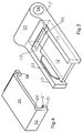
- the wing hinge is shown in perspective in FIGS.
- the belt flap 12 is simplified, that is to say without the shape described in FIG. 1 with regard to the adjusting means 19.
- Side webs 13 which project from the belt flap parallel to one another on the same side can be seen in FIG.
- the from the longitudinal edges of the band tab 12 projecting side webs 13 are longer than the said longitudinal edges and carry at their ends 13 'an axle sleeve 53, the sleeve bore 54 for receiving the bearing axis 15 shown in Figure 1 by means of a bearing bush 22.
- the bearing axis 15 is arranged eccentrically within the bearing bush 22. If the angular position of the bearing bush 22 is changed relative to the axle sleeve 53, the position of the bearing axis 15 changes accordingly, in particular vertically relative to the frame 27. By adjusting the angular positions of the bearing bush 22, an adjustment can be made vertically to the frame 27, namely a pressure adjustment of the wing 11. In order to achieve different adjustment positions, the bearing bush 22 is rotated. To secure different angular positions, the triangular recesses 50 shown in FIG. 1 are used, which are to be made to coincide with, for example, semicircular extensions of the axle sleeve 53, not shown. In a cross section formed by such an extension and a recess 50, a locking part, not shown, is introduced, which can be part of the axle cap 51 shown schematically in FIG. 2, for example.
- the axle sleeve 53 is provided on its side facing the adjusting means 19 with a hook web 55.
- the hook web 55 is L-shaped with an essentially radially protruding long L-leg and a short L-leg facing the wing 11, which is arranged essentially tangentially to the outer circumference of the axle sleeve 53.
- the hook web 55 serves to hook the cover cap 20.
- the cover cap 20 is provided with a hook web 56 on its narrow edge facing the axle sleeve 53.
- the hook web 56 is U-shaped and engages under the hook web 55 of the axle sleeve 53, as shown in FIG. 1.
- the side webs 13 are formed in one piece with the axle sleeve 53.
- the result is a very stable design that can withstand high radial loads.
- the hinge flap 12 can also be made in one piece with the axle sleeve 53 are connected, in which case suitable measures for shaping the hook web 53 must be taken.
- the cover cap At its end 20 'remote from the axis, the cover cap is U-shaped.
- the leg 31 engaging behind the band tab 12 is provided with a latching rib 31 ′ which engages in a correspondingly positioned latching notch arranged in the rear of the band tab 12 and here provides additional anchoring of the cover cap 20.
- the latching is practically insoluble with a corresponding design of the latching rib, so that the cover cap 20 as a whole does not offer a starting point in order to release either this latching or the hooking by means of the hook webs 55, 56.
- the side webs 13 are designed such that they have shoulders 33 which are adapted to the cover cap 20.
- the deposits 33 are so deep in the central region that they correspond approximately to the thickness of the cap wall. As a result, the cap 20 is supported vertically. In the area of the hook web 56 and the cap end 20 ', the steps 33 are adapted accordingly, so that the necessary clearance for the installation of the cover cap 20 is given.
- FIG. 5 shows a special configuration of the end 12 'of the hinge flap 12 which is remote from the axis and is here provided with a rounding 57.
- this rounding 57 there are no side webs 13 which are located on the band tab 12 outside of this rounding 57. These side webs are also provided with shoulders 33 in order to be able to support the associated cover cap 20 vertically.
- the outer contour of the cover cap 20 is similar to that of the hinge flap 12, and therefore also has a rounding in the region of its end 20 '.
- a cap edge 58 projects from this rounding, vertically to the band tab 12. The cap edge 58 extends between the ends of the side webs 13 around the entire rounding 57 and is latched to the end 12 ′′ of the band tab 12.
- the side webs 13 have rear engaging webs 60 at their ends on the edge of the cap, with which the inside of the cap edge 58 is engaged. This results in a clean closure of the interior of the wing hinge, combined with corresponding stabilization of the cover cap 20 by the rear gripping webs 60.
Landscapes
- Engineering & Computer Science (AREA)
- Mechanical Engineering (AREA)
- Hinges (AREA)
- Liquid Crystal (AREA)
Applications Claiming Priority (2)
| Application Number | Priority Date | Filing Date | Title |
|---|---|---|---|
| DE29807342U | 1998-04-24 | ||
| DE29807342U DE29807342U1 (de) | 1998-04-24 | 1998-04-24 | Tür- oder Fensterband |
Publications (3)
| Publication Number | Publication Date |
|---|---|
| EP0952291A2 true EP0952291A2 (fr) | 1999-10-27 |
| EP0952291A3 EP0952291A3 (fr) | 2003-01-29 |
| EP0952291B1 EP0952291B1 (fr) | 2005-08-24 |
Family
ID=8056176
Family Applications (1)
| Application Number | Title | Priority Date | Filing Date |
|---|---|---|---|
| EP99107731A Expired - Lifetime EP0952291B1 (fr) | 1998-04-24 | 1999-04-19 | Penture de porte ou de fenêtre |
Country Status (4)
| Country | Link |
|---|---|
| EP (1) | EP0952291B1 (fr) |
| AT (1) | ATE302889T1 (fr) |
| DE (2) | DE29807342U1 (fr) |
| PL (1) | PL190835B1 (fr) |
Families Citing this family (1)
| Publication number | Priority date | Publication date | Assignee | Title |
|---|---|---|---|---|
| CN105840026A (zh) * | 2016-05-25 | 2016-08-10 | 广东坚朗五金制品股份有限公司 | 连接结构、门窗合页结构及平开门窗 |
Citations (2)
| Publication number | Priority date | Publication date | Assignee | Title |
|---|---|---|---|---|
| DE3546253A1 (de) | 1985-12-28 | 1987-07-02 | Hahn Gmbh & Co Kg Dr | Band fuer tueren, fenster und dergleichen |
| DE29718528U1 (de) | 1997-10-18 | 1998-02-19 | Niemann, Hans Dieter, 50169 Kerpen | Tür- oder Fensterband |
Family Cites Families (11)
| Publication number | Priority date | Publication date | Assignee | Title |
|---|---|---|---|---|
| DE7317785U (de) * | 1973-08-30 | Hahn W Mechanische Werkstaetten | Band fur Türen, Fenster und dergl | |
| US3252179A (en) * | 1964-01-16 | 1966-05-24 | Swedish Crucible Steel Company | Fastener-concealing hinge leaf construction |
| DE7010559U (de) * | 1970-03-21 | 1970-12-17 | Hueck Fa E | Scharnierband, insbesondere fuer tueren und fenster. |
| DE3716601C1 (en) * | 1985-12-28 | 1988-10-13 | Hahn Gmbh & Co Kg Dr | Hinge for doors, windows and the like |
| DE9203038U1 (de) * | 1992-03-06 | 1992-04-30 | ANUBA-Beschläge X. Heine & Sohn GmbH, 7741 Vöhrenbach | Vorrichtung zur Andruckverstellung von Scharnierbändern, insbesondere von Türbändern |
| DE9315327U1 (de) * | 1993-10-11 | 1995-02-16 | Dr. Hahn GmbH & Co. KG., 41189 Mönchengladbach | Band für Türen, Fenster u.dgl. |
| DE9413892U1 (de) * | 1994-08-27 | 1995-12-21 | Dr. Hahn GmbH & Co. KG., 41189 Mönchengladbach | Band für Türen, Fenster u.dgl. |
| DE9413893U1 (de) * | 1994-08-27 | 1995-12-21 | Dr. Hahn GmbH & Co. KG., 41189 Mönchengladbach | Band für Türen, Fenster u.dgl. |
| DE9413891U1 (de) * | 1994-08-27 | 1995-12-21 | Dr. Hahn GmbH & Co. KG., 41189 Mönchengladbach | Band für Türen, Fenster u.dgl. |
| DE29720378U1 (de) * | 1997-11-18 | 1998-02-26 | Dorma Gmbh + Co. Kg, 58256 Ennepetal | Rahmenlose Glastür |
| DE29721037U1 (de) * | 1997-11-28 | 1999-04-22 | Niemann, Hans Dieter, 50169 Kerpen | Tür- oder Fensterband |
-
1998
- 1998-04-24 DE DE29807342U patent/DE29807342U1/de not_active Expired - Lifetime
-
1999
- 1999-04-19 AT AT99107731T patent/ATE302889T1/de active
- 1999-04-19 EP EP99107731A patent/EP0952291B1/fr not_active Expired - Lifetime
- 1999-04-19 DE DE59912447T patent/DE59912447D1/de not_active Expired - Lifetime
- 1999-04-21 PL PL332661A patent/PL190835B1/pl not_active IP Right Cessation
Patent Citations (2)
| Publication number | Priority date | Publication date | Assignee | Title |
|---|---|---|---|---|
| DE3546253A1 (de) | 1985-12-28 | 1987-07-02 | Hahn Gmbh & Co Kg Dr | Band fuer tueren, fenster und dergleichen |
| DE29718528U1 (de) | 1997-10-18 | 1998-02-19 | Niemann, Hans Dieter, 50169 Kerpen | Tür- oder Fensterband |
Also Published As
| Publication number | Publication date |
|---|---|
| PL332661A1 (en) | 1999-10-25 |
| DE29807342U1 (de) | 1999-09-02 |
| EP0952291B1 (fr) | 2005-08-24 |
| PL190835B1 (pl) | 2006-02-28 |
| EP0952291A3 (fr) | 2003-01-29 |
| ATE302889T1 (de) | 2005-09-15 |
| DE59912447D1 (de) | 2005-09-29 |
Similar Documents
| Publication | Publication Date | Title |
|---|---|---|
| DE4219681C2 (de) | Einstellbares Abhebescharnier | |
| DE3642127C2 (fr) | ||
| EP2055867A1 (fr) | Poignée dotée d'une garniture de fermeture | |
| EP1072745B1 (fr) | Ferrure de verrouillage pour fenêtres ou portes | |
| DE29721037U1 (de) | Tür- oder Fensterband | |
| EP2602412B1 (fr) | Agencement de ferrure | |
| EP1023515B1 (fr) | Paumelle de porte ou de fenetre | |
| DE9113206U1 (de) | Vorrichtung zum Einstellen der Schließkante an einem Tür- oder Fensterverschluß | |
| DE8710534U1 (de) | Profilschließzylinder mit Axialsicherung | |
| EP0952291A2 (fr) | Penture de porte ou de fenêtre | |
| EP1666688B1 (fr) | Charnière pour fenêtres, portes et similaires | |
| DE10309946B4 (de) | Schloß | |
| EP2169167A1 (fr) | Dispositif de réglage de la distance entre deux chariots se déplaçant sur un rail commun et procédé | |
| EP0495361B1 (fr) | Ferrure pour portes équipées de serrures encastrées à cylindre profilé | |
| CH709435B1 (de) | Einsteckschloss für einen Flügel einer Tür oder eines Fensters. | |
| DE69111947T2 (de) | Verbessertes Scharnier, insbesondere für ein Gefüge aus rohrförmigen Metallprofilen. | |
| DE3203518C2 (de) | Scharnierband | |
| DE102018101285A1 (de) | Eckverbinder | |
| DE10309947B4 (de) | Schloß | |
| DE2751148A1 (de) | Auf links- oder rechts-anschlag umstellbares drehstangen-moebelschloss | |
| DE9106906U1 (de) | Drehriegelverschluß | |
| EP1241308A2 (fr) | Dispositif de réglage d'une charnière | |
| EP3656955B1 (fr) | Gâche | |
| EP0945574B1 (fr) | Charnière pour portes, fenêtres ou similaires | |
| DE20105545U1 (de) | Band für Türen, Fenster o.dgl. |
Legal Events
| Date | Code | Title | Description |
|---|---|---|---|
| PUAI | Public reference made under article 153(3) epc to a published international application that has entered the european phase |
Free format text: ORIGINAL CODE: 0009012 |
|
| AK | Designated contracting states |
Kind code of ref document: A2 Designated state(s): AT BE CH CY DE DK ES FI FR GB GR IE IT LI LU MC NL PT SE |
|
| AX | Request for extension of the european patent |
Free format text: AL;LT;LV;MK;RO;SI |
|
| PUAL | Search report despatched |
Free format text: ORIGINAL CODE: 0009013 |
|
| AK | Designated contracting states |
Designated state(s): AT BE CH CY DE DK ES FI FR GB GR IE IT LI LU MC NL PT SE |
|
| AX | Request for extension of the european patent |
Extension state: AL LT LV MK RO SI |
|
| 17P | Request for examination filed |
Effective date: 20030702 |
|
| AKX | Designation fees paid |
Designated state(s): AT BE DE FR GB IT NL |
|
| 17Q | First examination report despatched |
Effective date: 20040312 |
|
| GRAP | Despatch of communication of intention to grant a patent |
Free format text: ORIGINAL CODE: EPIDOSNIGR1 |
|
| RIN1 | Information on inventor provided before grant (corrected) |
Inventor name: KRAEMER, STEPHAN DIPL.-ING. Inventor name: LANGE, PETER Inventor name: NIEMANN, HANS DIETER |
|
| GRAS | Grant fee paid |
Free format text: ORIGINAL CODE: EPIDOSNIGR3 |
|
| GRAA | (expected) grant |
Free format text: ORIGINAL CODE: 0009210 |
|
| AK | Designated contracting states |
Kind code of ref document: B1 Designated state(s): AT BE DE FR GB IT NL |
|
| REG | Reference to a national code |
Ref country code: GB Ref legal event code: FG4D Free format text: NOT ENGLISH |
|
| REF | Corresponds to: |
Ref document number: 59912447 Country of ref document: DE Date of ref document: 20050929 Kind code of ref document: P |
|
| GBT | Gb: translation of ep patent filed (gb section 77(6)(a)/1977) |
Effective date: 20051115 |
|
| ET | Fr: translation filed | ||
| PLBE | No opposition filed within time limit |
Free format text: ORIGINAL CODE: 0009261 |
|
| STAA | Information on the status of an ep patent application or granted ep patent |
Free format text: STATUS: NO OPPOSITION FILED WITHIN TIME LIMIT |
|
| 26N | No opposition filed |
Effective date: 20060526 |
|
| REG | Reference to a national code |
Ref country code: DE Ref legal event code: R082 Ref document number: 59912447 Country of ref document: DE Representative=s name: DRAUDT, AXEL, DIPL.-ING., DE Effective date: 20110705 Ref country code: DE Ref legal event code: R082 Ref document number: 59912447 Country of ref document: DE Representative=s name: AXEL DRAUDT, DE Effective date: 20110705 Ref country code: DE Ref legal event code: R081 Ref document number: 59912447 Country of ref document: DE Owner name: ROTO GLUSKE-BKV GMBH, DE Free format text: FORMER OWNER: NIEMANN, HANS DIETER, 50169 KERPEN, DE Effective date: 20110705 Ref country code: DE Ref legal event code: R081 Ref document number: 59912447 Country of ref document: DE Owner name: ROTO GLUSKE-BKV GMBH, DE Free format text: FORMER OWNER: HANS DIETER NIEMANN, 50169 KERPEN, DE Effective date: 20110705 |
|
| PGFP | Annual fee paid to national office [announced via postgrant information from national office to epo] |
Ref country code: AT Payment date: 20110414 Year of fee payment: 13 Ref country code: GB Payment date: 20110421 Year of fee payment: 13 Ref country code: BE Payment date: 20110414 Year of fee payment: 13 Ref country code: NL Payment date: 20110426 Year of fee payment: 13 |
|
| PGFP | Annual fee paid to national office [announced via postgrant information from national office to epo] |
Ref country code: IT Payment date: 20110422 Year of fee payment: 13 |
|
| PGFP | Annual fee paid to national office [announced via postgrant information from national office to epo] |
Ref country code: FR Payment date: 20120507 Year of fee payment: 14 |
|
| BERE | Be: lapsed |
Owner name: *NIEMANN HANS DIETER Effective date: 20120430 |
|
| REG | Reference to a national code |
Ref country code: NL Ref legal event code: V1 Effective date: 20121101 |
|
| REG | Reference to a national code |
Ref country code: AT Ref legal event code: MM01 Ref document number: 302889 Country of ref document: AT Kind code of ref document: T Effective date: 20120419 |
|
| GBPC | Gb: european patent ceased through non-payment of renewal fee |
Effective date: 20120419 |
|
| PG25 | Lapsed in a contracting state [announced via postgrant information from national office to epo] |
Ref country code: GB Free format text: LAPSE BECAUSE OF NON-PAYMENT OF DUE FEES Effective date: 20120419 Ref country code: AT Free format text: LAPSE BECAUSE OF NON-PAYMENT OF DUE FEES Effective date: 20120419 Ref country code: BE Free format text: LAPSE BECAUSE OF NON-PAYMENT OF DUE FEES Effective date: 20120430 |
|
| PG25 | Lapsed in a contracting state [announced via postgrant information from national office to epo] |
Ref country code: IT Free format text: LAPSE BECAUSE OF NON-PAYMENT OF DUE FEES Effective date: 20120419 |
|
| PG25 | Lapsed in a contracting state [announced via postgrant information from national office to epo] |
Ref country code: NL Free format text: LAPSE BECAUSE OF NON-PAYMENT OF DUE FEES Effective date: 20121101 |
|
| REG | Reference to a national code |
Ref country code: FR Ref legal event code: ST Effective date: 20131231 |
|
| PG25 | Lapsed in a contracting state [announced via postgrant information from national office to epo] |
Ref country code: FR Free format text: LAPSE BECAUSE OF NON-PAYMENT OF DUE FEES Effective date: 20130430 |
|
| PGFP | Annual fee paid to national office [announced via postgrant information from national office to epo] |
Ref country code: DE Payment date: 20150602 Year of fee payment: 17 |
|
| REG | Reference to a national code |
Ref country code: DE Ref legal event code: R119 Ref document number: 59912447 Country of ref document: DE |
|
| PG25 | Lapsed in a contracting state [announced via postgrant information from national office to epo] |
Ref country code: DE Free format text: LAPSE BECAUSE OF NON-PAYMENT OF DUE FEES Effective date: 20161101 |