EP0952291A2 - Door or window hinge - Google Patents
Door or window hinge Download PDFInfo
- Publication number
- EP0952291A2 EP0952291A2 EP99107731A EP99107731A EP0952291A2 EP 0952291 A2 EP0952291 A2 EP 0952291A2 EP 99107731 A EP99107731 A EP 99107731A EP 99107731 A EP99107731 A EP 99107731A EP 0952291 A2 EP0952291 A2 EP 0952291A2
- Authority
- EP
- European Patent Office
- Prior art keywords
- hinge
- door
- cover cap
- axle sleeve
- cap
- Prior art date
- Legal status (The legal status is an assumption and is not a legal conclusion. Google has not performed a legal analysis and makes no representation as to the accuracy of the status listed.)
- Granted
Links
Images



Classifications
-
- E—FIXED CONSTRUCTIONS
- E05—LOCKS; KEYS; WINDOW OR DOOR FITTINGS; SAFES
- E05D—HINGES OR SUSPENSION DEVICES FOR DOORS, WINDOWS OR WINGS
- E05D7/00—Hinges or pivots of special construction
- E05D7/04—Hinges adjustable relative to the wing or the frame
- E05D7/0415—Hinges adjustable relative to the wing or the frame with adjusting drive means
- E05D7/0423—Screw-and-nut mechanisms
-
- E—FIXED CONSTRUCTIONS
- E05—LOCKS; KEYS; WINDOW OR DOOR FITTINGS; SAFES
- E05D—HINGES OR SUSPENSION DEVICES FOR DOORS, WINDOWS OR WINGS
- E05D11/00—Additional features or accessories of hinges
- E05D11/0054—Covers, e.g. for protection
-
- E—FIXED CONSTRUCTIONS
- E05—LOCKS; KEYS; WINDOW OR DOOR FITTINGS; SAFES
- E05D—HINGES OR SUSPENSION DEVICES FOR DOORS, WINDOWS OR WINGS
- E05D7/00—Hinges or pivots of special construction
- E05D7/0009—Adjustable hinges
- E05D7/0018—Adjustable hinges at the hinge axis
- E05D7/0045—Adjustable hinges at the hinge axis in a radial direction
- E05D7/0054—Adjustable hinges at the hinge axis in a radial direction by means of eccentric parts
-
- E—FIXED CONSTRUCTIONS
- E05—LOCKS; KEYS; WINDOW OR DOOR FITTINGS; SAFES
- E05D—HINGES OR SUSPENSION DEVICES FOR DOORS, WINDOWS OR WINGS
- E05D7/00—Hinges or pivots of special construction
- E05D7/04—Hinges adjustable relative to the wing or the frame
- E05D2007/0484—Hinges adjustable relative to the wing or the frame in a radial direction
-
- E—FIXED CONSTRUCTIONS
- E05—LOCKS; KEYS; WINDOW OR DOOR FITTINGS; SAFES
- E05D—HINGES OR SUSPENSION DEVICES FOR DOORS, WINDOWS OR WINGS
- E05D5/00—Construction of single parts, e.g. the parts for attachment
- E05D5/02—Parts for attachment, e.g. flaps
- E05D5/0215—Parts for attachment, e.g. flaps for attachment to profile members or the like
- E05D5/0223—Parts for attachment, e.g. flaps for attachment to profile members or the like with parts, e.g. screws, extending through the profile wall or engaging profile grooves
- E05D5/023—Parts for attachment, e.g. flaps for attachment to profile members or the like with parts, e.g. screws, extending through the profile wall or engaging profile grooves with parts extending through the profile wall
-
- E—FIXED CONSTRUCTIONS
- E05—LOCKS; KEYS; WINDOW OR DOOR FITTINGS; SAFES
- E05D—HINGES OR SUSPENSION DEVICES FOR DOORS, WINDOWS OR WINGS
- E05D5/00—Construction of single parts, e.g. the parts for attachment
- E05D5/10—Pins, sockets or sleeves; Removable pins
- E05D5/14—Construction of sockets or sleeves
-
- E—FIXED CONSTRUCTIONS
- E05—LOCKS; KEYS; WINDOW OR DOOR FITTINGS; SAFES
- E05Y—INDEXING SCHEME ASSOCIATED WITH SUBCLASSES E05D AND E05F, RELATING TO CONSTRUCTION ELEMENTS, ELECTRIC CONTROL, POWER SUPPLY, POWER SIGNAL OR TRANSMISSION, USER INTERFACES, MOUNTING OR COUPLING, DETAILS, ACCESSORIES, AUXILIARY OPERATIONS NOT OTHERWISE PROVIDED FOR, APPLICATION THEREOF
- E05Y2800/00—Details, accessories and auxiliary operations not otherwise provided for
- E05Y2800/67—Materials; Strength alteration thereof
- E05Y2800/676—Plastics
-
- E—FIXED CONSTRUCTIONS
- E05—LOCKS; KEYS; WINDOW OR DOOR FITTINGS; SAFES
- E05Y—INDEXING SCHEME ASSOCIATED WITH SUBCLASSES E05D AND E05F, RELATING TO CONSTRUCTION ELEMENTS, ELECTRIC CONTROL, POWER SUPPLY, POWER SIGNAL OR TRANSMISSION, USER INTERFACES, MOUNTING OR COUPLING, DETAILS, ACCESSORIES, AUXILIARY OPERATIONS NOT OTHERWISE PROVIDED FOR, APPLICATION THEREOF
- E05Y2800/00—Details, accessories and auxiliary operations not otherwise provided for
- E05Y2800/67—Materials; Strength alteration thereof
- E05Y2800/682—Strength alteration by reinforcing, e.g. by applying ribs
-
- E—FIXED CONSTRUCTIONS
- E05—LOCKS; KEYS; WINDOW OR DOOR FITTINGS; SAFES
- E05Y—INDEXING SCHEME ASSOCIATED WITH SUBCLASSES E05D AND E05F, RELATING TO CONSTRUCTION ELEMENTS, ELECTRIC CONTROL, POWER SUPPLY, POWER SIGNAL OR TRANSMISSION, USER INTERFACES, MOUNTING OR COUPLING, DETAILS, ACCESSORIES, AUXILIARY OPERATIONS NOT OTHERWISE PROVIDED FOR, APPLICATION THEREOF
- E05Y2900/00—Application of doors, windows, wings or fittings thereof
- E05Y2900/10—Application of doors, windows, wings or fittings thereof for buildings or parts thereof
- E05Y2900/13—Type of wing
- E05Y2900/132—Doors
-
- E—FIXED CONSTRUCTIONS
- E05—LOCKS; KEYS; WINDOW OR DOOR FITTINGS; SAFES
- E05Y—INDEXING SCHEME ASSOCIATED WITH SUBCLASSES E05D AND E05F, RELATING TO CONSTRUCTION ELEMENTS, ELECTRIC CONTROL, POWER SUPPLY, POWER SIGNAL OR TRANSMISSION, USER INTERFACES, MOUNTING OR COUPLING, DETAILS, ACCESSORIES, AUXILIARY OPERATIONS NOT OTHERWISE PROVIDED FOR, APPLICATION THEREOF
- E05Y2900/00—Application of doors, windows, wings or fittings thereof
- E05Y2900/10—Application of doors, windows, wings or fittings thereof for buildings or parts thereof
- E05Y2900/13—Type of wing
- E05Y2900/148—Windows
Definitions
- the invention relates to a door or window hinge, with a hinge arranged on a door or window sash, which encompasses a bearing shaft held by a bearing block with an axle sleeve, with adjusting means for adjusting the hinge tab on the sash, and with a covering cap that overlaps the adjusting means , which is locked on the hinge flap side.
- a hinge with the aforementioned features is known from DE-OS 35 46 253.
- the cover cap prevents the actuating means from being easily accessible.
- Your hinge-side locking is designed so that it engages on a clamping plate with which the flat hinge is to be clamped to the wing by actuating fasteners engaging in the wing.
- the clamping plate is only of limited length compared to the entire hinge. As a result, the locking is of less stability.
- a door hinge which has a hinge, from which side webs project parallel to one another, which encompass a bearing axis held in a bearing block.
- the cover cap is U-shaped at both ends and encompasses one end around the bearing axis, the encapsulation being able to take place to such an extent that the band tab can be gripped behind in the area of the bearing block.
- the cover cap is locked at the far end.
- the invention is therefore based on the object of improving a door or window hinge with the features mentioned above in such a way that an improved load transfer of the hinge flap is achieved in the region of the bearing axis even in the event that the cover cap is latched on the hinge side.
- a cross-locking hooking is used to fix the cover cap on the hinge.
- the cross-shaped interlocking with the axle sleeve guarantees the desired stability, because the axle sleeve can be designed according to the stability requirements, for example sufficiently solid.
- the desired stable load transfer of the hinge plate in the region of the bearing axis is only dependent on the sufficiently stable design of the axle sleeve.
- the combination of the hooking of the cover cap at one end and the latching at its other end ensures the simple assembly of the cover cap with the hinge flap without impairing the connection security. It is not necessary to use an additional securing part. If necessary, the catch can be designed in such a way that the cover cap must be destroyed in order to remove it again.
- the latching can also be designed to be detachable, or instead of the latching, a releasable connection of the cover cap to the hinge flap is selected at its end remote from the axis.
- the band can be designed so that the axle sleeve has a hook web with which a hook web of the cover cap is hooked.
- the training of hook bars is in line with the training the axle sleeve and adapted to the design of the cover cap.
- the axle sleeve is a longitudinally extending element and the cover cap has an edge, so that in both cases hook webs can be produced easily and in a material-saving manner.
- the band can be designed such that the hook web of the axle sleeve is L-shaped and is gripped by the U-shaped hook web of the cover cap.
- the L-shape of the axle sleeve and the U-shape of the cover cap are advantageous to hook together, so that on the one hand the desired cross-form fit is achieved, but on the other hand a flat outer surface of the cover cap with the surrounding areas of the wing hinge or its axle sleeve, etc.
- the hook web of the axle sleeve is arranged on the hinge between its axle sleeve and the adjusting means.
- the connection point is close to the bearing axis, so that the cover cap covers the largest possible space above the belt tab, in which space the actuating means are located.
- reaching around the bearing axis is avoided, so that the cover cap is not very complex or relatively short. This also benefits their stability.
- axle sleeve and its hook web are formed in one piece. This facilitates the manufacture of the wing hinge.
- the formation of the hook web on the axle sleeve is e.g. by injection molding without further ado and in the sense of the desired strength design.
- axle sleeve is in one piece with the side webs of the hinge tab from which they project in parallel.
- the side bars stabilize the wing hinge with their one-piece and, if necessary, massive training with the axle sleeve.
- Their mutually parallel projection defines the space that receives the adjusting means and is to be covered by the cover cap.
- the tape is advantageously designed so that the side webs of the tape tab each have a shoulder, in each of which an edge of the cover cap is fitted in a supported manner.
- the offset of the side webs prevent the cover cap from moving in the direction of the hinge, which could cause it to become disengaged from the axle sleeve.
- the stabilized fit of the cover cap also resists attempts to break in, particularly in the case of hinges on the outside of the door or on the outside of the window.
- the formation of the band can advantageously take place in such a way that the band flap is rounded at its end remote from the axis and its side webs are present outside the rounding, and that the cover cap is designed with an end remote from the axis adapted to the rounding of the band flap.
- the cover cap is used to form the space in which the adjusting means are to be accommodated. A corresponding enlargement is unproblematic because the cover cap can be assembled very stably with the other parts of the wing hinge.
- a further development of the above-described band is characterized in that the cover cap has a cap edge projecting vertically to the band flap, which is locked over the entire rounding at the end of the band flap remote from the axis.
- the cap edge projecting vertically to the band flap means, with an appealing exterior, an optimization of the space for accommodating adjusting means while at the same time the cover cap is securely seated by latching the cap edge over the entire rounding of the band flap.
- the door hinge 10 shown in FIGS. 1, 2 is attached on the one hand to a wing 11 and on the other hand to a fixed frame 27. Both frames are made of plastic, for example, and are provided in a central hollow chamber 35 or 36 with a reinforcement profile 37 or 38.
- the wing 11 can be pivoted in the direction of arrow 39 to open it.
- the band 10 is correspondingly articulated.
- the band 10 has a bearing block 28 which is fixedly attached to the frame 27 and which, in a known manner, has a bearing axis 15 which, according to FIG Bearing part allowed, which is attached to the wing 11.
- the band tab 12 is fastened with a clamping plate 17, which in turn rests on the contact surface 12 ′ of the band tab 12.
- the clamping plate 17 is not adjustable in the frame plane, as can be seen from the inlet pin 40, which is firmly seated in the clamping plate 17 at one end and engages with the other end in a hole in the frame 11.
- the clamping plate 17 has fastening means 18 in the form of fastening screws 41 shown in FIG. 1, which pass through elongated holes 42 in the hinge 12 and can be tightened so that the clamping plate 17 clamps the hinge 12 on the wing 11.
- fastening means 18 or fastening screws per elongated hole 42, as shown in FIG. 2.
- the band flap 12 can be adjusted in its longitudinal direction when the locomotive core of the screws 41 is used. Such an adjustment serves to be able to make the horizontal adjustment of the sash 11 relative to the frame 27 which is required in the frame plane.
- Adjustment means 19 in the form of an adjusting screw 43 and an adjusting nut 44 are used to adjust the hinge flap 12. Both are partly housed in recesses in the hinge flap 12 and partly in recesses in the clamping plate 17, so that the latter two lie flat on one another accordingly.
- the adjusting screw 43 engages with its head 43 ′ in a recess 45 of the hinge 12 and the adjusting screw 44 is fixed in a recess 45 of the clamping plate 17.
- the head 43 'of the adjusting screw 43 is provided with an internal polygonal recess, not shown, in which an adjusting key can engage.
- the hinge flap 12 is provided with a longitudinal slot 47 according to FIG.
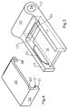
- the wing hinge is shown in perspective in FIGS.
- the belt flap 12 is simplified, that is to say without the shape described in FIG. 1 with regard to the adjusting means 19.
- Side webs 13 which project from the belt flap parallel to one another on the same side can be seen in FIG.
- the from the longitudinal edges of the band tab 12 projecting side webs 13 are longer than the said longitudinal edges and carry at their ends 13 'an axle sleeve 53, the sleeve bore 54 for receiving the bearing axis 15 shown in Figure 1 by means of a bearing bush 22.
- the bearing axis 15 is arranged eccentrically within the bearing bush 22. If the angular position of the bearing bush 22 is changed relative to the axle sleeve 53, the position of the bearing axis 15 changes accordingly, in particular vertically relative to the frame 27. By adjusting the angular positions of the bearing bush 22, an adjustment can be made vertically to the frame 27, namely a pressure adjustment of the wing 11. In order to achieve different adjustment positions, the bearing bush 22 is rotated. To secure different angular positions, the triangular recesses 50 shown in FIG. 1 are used, which are to be made to coincide with, for example, semicircular extensions of the axle sleeve 53, not shown. In a cross section formed by such an extension and a recess 50, a locking part, not shown, is introduced, which can be part of the axle cap 51 shown schematically in FIG. 2, for example.
- the axle sleeve 53 is provided on its side facing the adjusting means 19 with a hook web 55.
- the hook web 55 is L-shaped with an essentially radially protruding long L-leg and a short L-leg facing the wing 11, which is arranged essentially tangentially to the outer circumference of the axle sleeve 53.
- the hook web 55 serves to hook the cover cap 20.
- the cover cap 20 is provided with a hook web 56 on its narrow edge facing the axle sleeve 53.
- the hook web 56 is U-shaped and engages under the hook web 55 of the axle sleeve 53, as shown in FIG. 1.
- the side webs 13 are formed in one piece with the axle sleeve 53.
- the result is a very stable design that can withstand high radial loads.
- the hinge flap 12 can also be made in one piece with the axle sleeve 53 are connected, in which case suitable measures for shaping the hook web 53 must be taken.
- the cover cap At its end 20 'remote from the axis, the cover cap is U-shaped.
- the leg 31 engaging behind the band tab 12 is provided with a latching rib 31 ′ which engages in a correspondingly positioned latching notch arranged in the rear of the band tab 12 and here provides additional anchoring of the cover cap 20.
- the latching is practically insoluble with a corresponding design of the latching rib, so that the cover cap 20 as a whole does not offer a starting point in order to release either this latching or the hooking by means of the hook webs 55, 56.
- the side webs 13 are designed such that they have shoulders 33 which are adapted to the cover cap 20.
- the deposits 33 are so deep in the central region that they correspond approximately to the thickness of the cap wall. As a result, the cap 20 is supported vertically. In the area of the hook web 56 and the cap end 20 ', the steps 33 are adapted accordingly, so that the necessary clearance for the installation of the cover cap 20 is given.
- FIG. 5 shows a special configuration of the end 12 'of the hinge flap 12 which is remote from the axis and is here provided with a rounding 57.
- this rounding 57 there are no side webs 13 which are located on the band tab 12 outside of this rounding 57. These side webs are also provided with shoulders 33 in order to be able to support the associated cover cap 20 vertically.
- the outer contour of the cover cap 20 is similar to that of the hinge flap 12, and therefore also has a rounding in the region of its end 20 '.
- a cap edge 58 projects from this rounding, vertically to the band tab 12. The cap edge 58 extends between the ends of the side webs 13 around the entire rounding 57 and is latched to the end 12 ′′ of the band tab 12.
- the side webs 13 have rear engaging webs 60 at their ends on the edge of the cap, with which the inside of the cap edge 58 is engaged. This results in a clean closure of the interior of the wing hinge, combined with corresponding stabilization of the cover cap 20 by the rear gripping webs 60.
Landscapes
- Engineering & Computer Science (AREA)
- Mechanical Engineering (AREA)
- Hinges (AREA)
- Liquid Crystal (AREA)
Abstract
Description
Die Erfindung bezieht sich auf ein Tür- oder Fensterband, mit einem an einem Tür- oder Fensterflügel angeordneten Bandlappen, der mit einer Achshülse eine von einem Lagerbock gehaltene Lagerachse umgreift, mit Stellmitteln zum Verstellen des Bandlappens am Flügel, und mit einer die Stellmittel übergreifenden Abdeckkappe, die bandlappenseitig verrastet ist.The invention relates to a door or window hinge, with a hinge arranged on a door or window sash, which encompasses a bearing shaft held by a bearing block with an axle sleeve, with adjusting means for adjusting the hinge tab on the sash, and with a covering cap that overlaps the adjusting means , which is locked on the hinge flap side.
Ein Türband mit den vorgenannten Merkmalen ist aus der DE-OS 35 46 253 bekannt. Die Abdeckkappe verhindert, daß die Stellmittel ohne weiteres zugänglich sind. Ihre bandlappenseitige Verrastung ist so ausgebildet, daß sie an einer Klemmplatte angreift, mit der der flache Bandlappen durch Betätigung von in den Flügel eingreifenden Befestigungsmitteln am Flügel festzuklemmen ist. Die Klemmplatte ist nur von begrenzter Länge, verglichen mit dem gesamten Bandlappen. Infolgedessen ist die Verrastung von minderer Stabilität.A hinge with the aforementioned features is known from DE-OS 35 46 253. The cover cap prevents the actuating means from being easily accessible. Your hinge-side locking is designed so that it engages on a clamping plate with which the flat hinge is to be clamped to the wing by actuating fasteners engaging in the wing. The clamping plate is only of limited length compared to the entire hinge. As a result, the locking is of less stability.
Aus der deutschen Gebrauchsmusterschrift 297 18 528 ist ein Türband bekannt, das einen Bandlappen hat, von dem Seitenstege einander parallel vorspringen, die eine in einem Lagerbock gehaltene Lagerachse umgreifen. Es ist eine Abdeckkappe vorhanden, welche Stellmittel zum Verstellen des Bandlappens am Flügel übergreift. Die Abdeckkappe ist an beiden Enden U-förmig ausgebildet und umgreift mit einem Ende die Lagerachse, wobei das Umgreifen soweit erfolgen kann, daß der Bandlappen im Bereich des Lagerbocks hintergriffen werden kann. Am achsfernen Ende ist die Abdeckkappe verrastet. Obwohl die die Lagerachse umgreifende Kappe zur Stabilisierung des Bandes zwischen die Seitenstegen des Bandlappens herangezogen wird, läßt eine optimale Lastabtragung zu wünschen übrig.From the German utility model 297 18 528, a door hinge is known which has a hinge, from which side webs project parallel to one another, which encompass a bearing axis held in a bearing block. There is a cover cap which overlaps adjusting means for adjusting the hinge flap on the wing. The cover cap is U-shaped at both ends and encompasses one end around the bearing axis, the encapsulation being able to take place to such an extent that the band tab can be gripped behind in the area of the bearing block. The cover cap is locked at the far end. Although the cap around the bearing axis for stabilization of the tape between the side webs of the tape tab leaves an optimal load transfer to be desired.
Der Erfindung liegt daher die Aufgabe zugrunde, ein Tür- oder Fensterband mit den eingangs genannten Merkmalen so zu verbessern, daß im Bereich der Lagerachse eine verbesserte Lastabtragung des Bandlappens auch für den Fall erreicht wird, daß die Abdeckkappe bandlappenseitig verrastet ist.The invention is therefore based on the object of improving a door or window hinge with the features mentioned above in such a way that an improved load transfer of the hinge flap is achieved in the region of the bearing axis even in the event that the cover cap is latched on the hinge side.
Diese Aufgabe wird dadurch gelöst, daß die an ihrem achsfernen Ende verrastete Abdeckkappe mit der Achshülse querformschlüssig verhakt ist.This object is achieved in that the cover cap, which is locked at its end remote from the axis, is hooked to the axle sleeve in a cross-positive manner.
Für die Erfindung ist von Bedeutung, daß eine querformschlüssige Verhakung eingesetzt wird, um die Abdeckkappe am Bandlappen festzulegen. Die querformschlüssige Verhakung mit der Achshülse garantiert die gewünschte Stabilität, denn die Achshülse kann den Stabilitätsanforderungen entsprechend ausgebildet werden, beispielsweise hinreichend massiv. Infolgedessen ist die gewünschte stabile Lastabtragung des Bandlappens im Bereich der Lagerachse nur von der genügend stabilen Ausbildung der Achshülse abhängig. Die Kombination der Verhakung der Abdeckkappe an ihrem einen Ende und der Verrastung an ihrem anderen Ende gewährleistet den einfachen Zusammenbau der Abdeckkappe mit dem Bandlappen, ohne daß dabei die Verbindungssicherheit beeinträchtigt wird. Es ist nicht erforderlich, ein zusätzliches Sicherungsteil einzusetzen. Die Verrastung kann notfalls so ausgebildet werden, daß die Abdeckkappe zerstört werden muß, um sie wieder zu entfernen. Damit ist jedem Sicherheitserfordernis auch bei nach außen aufgehenden Türen Genüge getan. Sofern ein derartige Sicherung der Abdeckkappe nicht erforderlich ist, kann die Verrastung auch lösbar ausgebildet werden oder anstelle der Verrastung wird eine lösbare Verbindung der Abdeckkappe mit dem Bandlappen an ihrem achsfernen Ende gewählt.It is important for the invention that a cross-locking hooking is used to fix the cover cap on the hinge. The cross-shaped interlocking with the axle sleeve guarantees the desired stability, because the axle sleeve can be designed according to the stability requirements, for example sufficiently solid. As a result, the desired stable load transfer of the hinge plate in the region of the bearing axis is only dependent on the sufficiently stable design of the axle sleeve. The combination of the hooking of the cover cap at one end and the latching at its other end ensures the simple assembly of the cover cap with the hinge flap without impairing the connection security. It is not necessary to use an additional securing part. If necessary, the catch can be designed in such a way that the cover cap must be destroyed in order to remove it again. This fulfills every security requirement, even with doors that open outwards. If such a securing of the cover cap is not required, the latching can also be designed to be detachable, or instead of the latching, a releasable connection of the cover cap to the hinge flap is selected at its end remote from the axis.
Das Band kann so ausgebildet werden, daß die Achshülse einen Hakensteg hat, mit dem ein Hakensteg der Abdeckkappe verhakt ist. Die Ausbildung von Hakenstegen ist an die Ausbildung der Achshülse und an die Ausbildung der Abdeckkappe angepaßt. Die Achshülse ist ein sich längs erstreckendes Element und die Abdeckkappe hat eine Kante, so daß sich in beiden Fällen Hakenstege einfach und werkstoffsparend herstellen lassen.The band can be designed so that the axle sleeve has a hook web with which a hook web of the cover cap is hooked. The training of hook bars is in line with the training the axle sleeve and adapted to the design of the cover cap. The axle sleeve is a longitudinally extending element and the cover cap has an edge, so that in both cases hook webs can be produced easily and in a material-saving manner.
Insbesondere kann das Band so ausgebildet werden, daß der Hakensteg der Achshülse L-förmig ausgebildet und von dem U-förmig ausgebildeten Hakensteg der Abdeckkappe untergriffen ist. Die L-Form der Achshülse und die U-Form der Abdeckkappe sind vorteilhaft miteinander zu verhaken, so daß einerseits die gewünschte Querformschlüssigkeit erreicht wird, andererseits aber auch eine gleichliegende Außenfläche der Abdeckkappe mit den umgebenden Bereichen des Flügelbandes bzw. dessen Achshülse usw.In particular, the band can be designed such that the hook web of the axle sleeve is L-shaped and is gripped by the U-shaped hook web of the cover cap. The L-shape of the axle sleeve and the U-shape of the cover cap are advantageous to hook together, so that on the one hand the desired cross-form fit is achieved, but on the other hand a flat outer surface of the cover cap with the surrounding areas of the wing hinge or its axle sleeve, etc.
Von besonderem Vorteil ist es, wenn der Hakensteg der Achshülse am Bandlappen zwischen dessen Achshülse und den Stellmitteln angeordnet ist. In diesem Fall ist die Verbindungsstelle lagerachsennah, so daß die Abdeckkappe den größtmöglichen Raum oberhalb des Bandlappens abdeckt, in welchem Raum sich die Stellmittel befinden. Zugleich wird ein Umgreifen der Lagerachse vermieden, so daß die Abdeckkappe wenig aufwendig bzw. relativ kurz ausgebildet ist. Das kommt auch ihrer Stabilität zugute.It is particularly advantageous if the hook web of the axle sleeve is arranged on the hinge between its axle sleeve and the adjusting means. In this case, the connection point is close to the bearing axis, so that the cover cap covers the largest possible space above the belt tab, in which space the actuating means are located. At the same time, reaching around the bearing axis is avoided, so that the cover cap is not very complex or relatively short. This also benefits their stability.
Es wird bevorzugt, wenn die Achshülse und ihr Hakensteg einstückig ausgebildet sind. Hierdurch wird die Herstellung des Flügelbandes erleichtert. Die Anformung des Hakensteges an die Achshülse ist bei dessen Herstellung z.B. durch Spritzgießen ohne weiteres und im Sinne der gewünschten Festigkeitsgestaltung möglich.It is preferred if the axle sleeve and its hook web are formed in one piece. This facilitates the manufacture of the wing hinge. The formation of the hook web on the axle sleeve is e.g. by injection molding without further ado and in the sense of the desired strength design.
Es wird weiterhin bevorzugt, wenn die Achshülse mit Seitenstegen des Bandlappens einstückig ist, von dem sie einander parallel vorspringen. Die Seitenstege stabilisieren das Flügelband durch ihre einstückige und bedarfsweise massive Ausbildung mit der Achshülse. Ihr einander paralleles Vorspringen definiert den Raum, der die Stellmittel aufnimmt und von der Abdeckkappe abzudecken ist.It is further preferred if the axle sleeve is in one piece with the side webs of the hinge tab from which they project in parallel. The side bars stabilize the wing hinge with their one-piece and, if necessary, massive training with the axle sleeve. Their mutually parallel projection defines the space that receives the adjusting means and is to be covered by the cover cap.
Das Band wird vorteilhafterweise so ausgebildet, daß die Seitenstege des Bandlappens jeweils eine Absetzung aufweisen, in die je eine Kante der Abdeckkappe abgestützt eingepaßt ist. Es ergibt sich ein vergleichsweise paßgenauer Sitz der Abdeckkappe zwischen den Seitenstegen. Die Absetzungen der Seitenstege verhindern ein Verschieben der Abdeckkappe in Richtung zum Bandlappen hin, wodurch ihre Verhakung mit der Achshülse außer Eingriff geraten könnte. Der stabilisierte Sitz der Abdeckkappe widersteht auch Einbruchsversuchen, insbesondere bei türaußenseitig oder fensteraußenseitig liegenden Bändern.The tape is advantageously designed so that the side webs of the tape tab each have a shoulder, in each of which an edge of the cover cap is fitted in a supported manner. There is a comparatively precise fit of the cover cap between the side webs. The offset of the side webs prevent the cover cap from moving in the direction of the hinge, which could cause it to become disengaged from the axle sleeve. The stabilized fit of the cover cap also resists attempts to break in, particularly in the case of hinges on the outside of the door or on the outside of the window.
Die Ausbildung des Bandes kann vorteilhafterweise so erfolgen, daß der Bandlappen an seinem achsfernen Ende abgerundet ist und seine Seitenstege außerhalb der Abrundung vorhanden sind, und daß die Abdeckkappe mit einem der Abrundung des Bandlappens angepaßten achsfernen Ende ausgebildet ist. Durch die Abrundung des achsfernen Endes des Bandlappens und der entsprechend angepaßten Ausbildung des achsfernen Endes der Abdeckkappe wird zunächst eine ansprechende Ausbildung des Flügelbandes erreicht. Darüber hinaus wird die Abdeckkappe zur Ausbildung desjenigen Raumes herbeigezogen, in dem die Stellmittel unterzubringen sind. Eine entsprechende Vergrößerung ist deswegen unproblematisch, weil die Abdeckkappe mit den übrigen Teilen des Flügelbandes sehr stabil zusammengebaut sein kann.The formation of the band can advantageously take place in such a way that the band flap is rounded at its end remote from the axis and its side webs are present outside the rounding, and that the cover cap is designed with an end remote from the axis adapted to the rounding of the band flap. By rounding off the end of the hinge flap remote from the axis and the correspondingly adapted design of the end of the cover cap away from the axis, an appealing design of the wing hinge is first achieved. In addition, the cover cap is used to form the space in which the adjusting means are to be accommodated. A corresponding enlargement is unproblematic because the cover cap can be assembled very stably with the other parts of the wing hinge.
Eine Weiterbildung des vorbeschriebenen Bandes zeichnet sich dadurch aus, daß die Abdeckkappe einen vertikal zum Bandlappen vorspringenden Kappenrand hat, der an dem achsfernen Ende des Bandlappens über die gesamte Abrundung verrastet ist. Der vertikal zum Bandlappen vorspringende Kappenrand bedeutet bei ansprechendem Äußeren eine Optimierung des Raumes zur Unterbringung von Stellmitteln bei zugleich sicherem Sitz der Abdeckkappe durch Verrastung des Kappenrandes über die gesamte Abrundung des Bandlappens.A further development of the above-described band is characterized in that the cover cap has a cap edge projecting vertically to the band flap, which is locked over the entire rounding at the end of the band flap remote from the axis. The cap edge projecting vertically to the band flap means, with an appealing exterior, an optimization of the space for accommodating adjusting means while at the same time the cover cap is securely seated by latching the cap edge over the entire rounding of the band flap.
Als weiteres Mittel zur Stabilisierung und Sicherung des Flügelbandes gegen Aufbruchversuche kann angesehen werden, wenn der Kappenrand von den Seitenstegen hintergriffen ist. Die Seitenstege verschließen den seitlichen Anschluß zwischen der Abdeckkappe und den Stegen des Flügelbandes, wobei sie spezielle Anlageflächen bilden.Another means of stabilizing and securing the wing hinge against attempts to break open can be seen when the edge of the cap is caught behind by the side bars. The side webs close the lateral connection between the cover cap and the webs of the wing hinge, whereby they form special contact surfaces.
Die Erfindung wird anhand eines in der Zeichnung dargestellten Ausführungsbeispiels erläutert. Es zeigt:
- Fig.1
- einen Querschnitt durch einen Türaufbau im Bereich eines Türbandes,
- Fig.2
- eine Aufsicht auf ein Türband gemäß der Fig.1 bei teilweise weggebrochen dargestellter Abdeckkappe,
- Fig.3
- eine perspektivische Ansicht eines Flügelbandes ohne Abdeckkappe in schematisierter Darstellung,
- Fig.4
- eine zu dem Flügelband der Fig.3 gehörige Abdeckkappe in ebenfalls schematisierter Darstellung,
- Fig.5
- eine abgewandelte Ausführungsform eines Flügelbandes im achsfernen Endbereich,
- Fig.6
- die dem Flügelband der Fig.5 zugehörige Abdeckkappe im Endbereich, und
- Fig.7
- eine Querschnittsdarstellung der Abdeckkappe der Fig.6.
- Fig. 1
- a cross section through a door structure in the region of a door hinge,
- Fig. 2
- 2 shows a top view of a door hinge according to FIG. 1 with the cover cap shown partially broken away,
- Fig. 3
- 2 shows a perspective view of a wing hinge without a cover cap in a schematic illustration,
- Fig. 4
- a cover cap belonging to the wing hinge of FIG. 3 in a likewise schematic representation,
- Fig. 5
- a modified embodiment of a wing hinge in the end region remote from the axis,
- Fig. 6
- the cover cap associated with the wing hinge of FIG. 5 in the end region, and
- Fig. 7
- a cross-sectional view of the cover of Figure 6.
Das in den Fig.1,2 dargestellte Türband 10 ist einerseits an einem Flügel 11 und andererseits an einem feststehenden Rahmen 27 angeschlagen. Beide Rahmen bestehen beispielsweise aus Kunststoff und sind in einer zentralen Hohlkammer 35 bzw. 36 mit einem Verstärkungsprofil 37 bzw. 38 versehen. Der Flügel 11 kann im Sinne des Pfeils 39 verschwenkt werden, um ihn zu öffnen. Hierzu ist das Band 10 entsprechend gelenkig ausgebildet.The door hinge 10 shown in FIGS. 1, 2 is attached on the one hand to a
Das Band 10 besitzt einen am Rahmen 27 fest angeschlagenen Lagerbock 28, der in bekannter Weise eine Lagerachse 15 hat, die sich gemäß Fig.2 parallel zur Rahmen- bzw. Türebene vertikal erstreckt und an ihrem oberen Ende die gelenkige Anordnung eines zum Lagerbock 28 weiteren Lagerteils gestattet, das am Flügel 11 befestigt wird. Wesentlicher Bestandteil dieses zweiten Lagerteils, nämlich des Flügelbandes, ist ein Bandlappen 12, der direkt auf der Flügelrahmenaußenfläche 11' aufliegt. Die Befestigung des Bandlappens 12 erfolgt mit einer Klemmplatte 17, die ihrerseits auf der Auflagefläche 12' des Bandlappens 12 aufliegt. Die Klemmplatte 17 ist in der Rahmenebene unverstellbar, wie der Einlaßstift 40 erkennen läßt, der mit einem Ende fest in der Klemmplatte 17 sitzt und mit dem anderen Ende in ein Loch des Rahmens 11 eingreift. Die Klemmplatte 17 hat Befestigungsmittel 18 in Gestalt von in Fig.1 dargestellten Befestigungsschrauben 41, welche Langlöcher 42 des Bandlappens 12 durchgreifen und so fest gezogen werden können, daß die Klemmplatte 17 den Bandlappen 12 am Flügel 11 festklemmt. Es sind je Langloch 42 mehrere Befestigungsmittel 18 bzw. Befestigungsschrauben vorhanden, wie Fig. 2 zeigt. Infolgedessen kann der Bandlappen 12 bei einem Lokkern der Schrauben 41 in seiner Längsrichtung verstellt werden. Eine derartige Verstellung dient dazu, die in der Rahmenebene erforderliche horizontale Justierung des Flügels 11 relativ zum Rahmen 27 vornehmen zu können.The
Zur Verstellung des Bandlappens 12 dienen Stellmittel 19 in Gestalt einer Stellschraube 43 und einer Stellmutter 44. Beide sind teils in Ausnehmungen des Bandlappens 12 und teils in Ausnehmungen der Klemmplatte 17 untergebracht, so daß die beiden letztgenannten entsprechend flächig aufeinander liegen. Die Stellschraube 43 greift mit ihrem Kopf 43' in eine Ausnehmung 45 des Bandlappens 12 und die Stellschraube 44 ist in einer Ausnehmung 45 der Klemmplatte 17 festgelegt. Der Kopf 43' der Stellschraube 43 ist mit einer nicht dargestellten Innenmehrkant-Ausnehmung versehen, in die ein Stellschlüssel eingreifen kann. Eine Verdrehung führt infolge der in der Klemmplatte 17 festgelegten Stellmutter 44 dazu, daß der Schraubenkopf 43' den Bandlappen 12 zwischen der Klemmplatte 17 und dem Flügel 11 verschiebt. Damit diese Verschiebung durch die Stellmutter 44 nicht behindert wird, ist der Bandlappen 12 gemäß Fig.1 mit einem Längsschlitz 47 versehen.Adjustment means 19 in the form of an adjusting
In den Fig.3,4 ist das Flügelband perspektivisch dargestellt. Der Bandlappen 12 ist vereinfacht, also ohne die in Fig.1 beschriebene Formgebung im Hinblick auf die Stellmittel 19. Ersichtlich sind in Fig.3 Seitenstege 13, die vom Bandlappen einander parallel zu derselben Seite vorspringen. Die von den Längskanten des Bandlappens 12 vorspringenden Seitenstege 13 sind länger als die genannten Längskanten und tragen an ihren Enden 13' eine Achshülse 53, deren Hülsenbohrung 54 zur Aufnahme der in Fig.1 dargestellten Lagerachse 15 mittels einer Lagerbuchse 22 dient.The wing hinge is shown in perspective in FIGS. The
Innerhalb der Lagerbuchse 22 ist die Lagerachse 15 exzentrisch angeordnet. Wird die Winkelstellung der Lagerbuchse 22 relativ zur Achshülse 53 verändert, so verändert sich entsprechend die Position der Lagerachse 15, und zwar insbesondere vertikal zum Rahmen 27. Durch Einstellung der Winkelstellungen der Lagerbuchse 22 kann dementsprechend eine Justierung vertikal zum Rahmen 27 erfolgen, nämlich eine Andruckjustierung des Flügels 11. Um unterschiedliche Justierstellungen zu erreichen, wird die Lagerbuchse 22 verdreht. Zur Sicherung unterschiedlicher Winkelstellungen dienen die in Fig.1 dargestellten dreieckigen Ausnehmungen 50, die mit beispielsweise halbkreisförmigen, nicht dargestellten Erweiterungen der Achshülse 53 zur Deckung zu bringen sind. In einen durch eine solche Erweiterung und eine Ausnehmung 50 gemeinsam gebildeten Querschnitt wird ein nicht dargestelltes Sperrteil eingebracht, das beispielsweise Bestandteil der in Fig.2 schematisch dargestellten Achsenkappe 51 sein kann.The bearing
Die Achshülse 53 ist an ihrer den Stellmitteln 19 zugewendeten Seite mit einem Hakensteg 55 versehen. Der Hakensteg 55 ist L-förmig mit einem im wesentlichen radial abstehenden langen L-Schenkel und einem dem Flügel 11 zugewendeten kurzen L-Schenkel, der im wesentlichen tangential zum Außenumfang der Achshülse 53 angeordnet ist. Der Hakensteg 55 dient dem Verhaken der Abdeckkappe 20. Die Abdeckkappe 20 ist an ihrer der Achshülse 53 zugewendeten Schmalkante mit einem Hakensteg 56 versehen. Der Hakensteg 56 ist U-förmig ausgebildet und untergreift den Hakensteg 55 der Achshülse 53, wie es in Fig. 1 dargestellt ist.The
Die Seitenstege 13 sind mit der Achshülse 53 einstückig ausgebildet. Es ergibt sich eine sehr stabile Gestaltung, die auch hohen radialen Belastungen standhält. Nötigenfalls kann hierzu der Bandlappen 12 ebenfalls mit der Achshülse 53 einstückig verbunden werden, wobei dann geeignete Maßnahmen zur Formung des Hakenstegs 53 getroffen werden müssen.The
An ihrem achsfernen Ende 20' ist die Abdeckkappe U-förmig ausgebildet. An einer den U-Boden 52 bildenden Abwinkelung sitzt als weitere Abwinkelung ein Schenkel 31, der den Bandlappen 12 hintergreift. Im U-Boden 52 befindet sich gemäß Fig.1 eine Bohrung, die durch ein Stopfen 53 verschlossen ist. Nach der Entfernung dieses Stopfens 53 ist der Kopf 43' der Verstellschraube 43 zugänglich und kann ohne Abnehmen der Abdeckkappe 20 mittels Eingriffs eines Einsteckschlüssels in die nicht dargestellte Innenmehrkantausnehmung verdreht werden.At its end 20 'remote from the axis, the cover cap is U-shaped. A
Der den Bandlappen 12 hintergreifende Schenkel 31 ist mit einer Rastrippe 31' versehen, die in eine entsprechend positionierte, in der Rückseite des Bandlappens 12 angeordnete Rastkerbe eingreift und hier für eine zusätzliche Verankerung der Abdeckkappe 20 sorgt. Die Verrastung ist bei entsprechender Ausbildung der Rastrippe praktisch unlösbar, so daß die Abdeckkappe 20 insgesamt keinen Ansatzpunkt bietet, um entweder diese Verrastung oder die Verhakung mittels der Hakenstege 55,56 zu lösen. Das gilt insbesondere im Hinblick darauf, daß die Außenfläche der Abdeckkappe 20 gemäß Fig.1 sowohl mit der Außenfläche des Hakenstegs 55 fluchtet, wie auch mit den sichtseitigen Kanten der Seitenstege 13, so daß eine glatte Außenfläche gegeben ist, die keinen Ansatz für ein Einbruchswerkzeug aufweist.The
Damit die Kappe 20 nicht in Richtung zum Bandlappen 12 verschoben werden kann, sind die Seitenstege 13 dahingehend ausgebildet, daß sie Absetzungen 33 aufweisen, die der Abdeckkappe 20 angepaßt sind. Die Absetzungen 33 sind im Mittelbereich so tief, daß sie etwa der Dicke der Kappenwand entsprechen. Infolgedessen ist die Abdeckkappe 20 vertikal abgestützt. Im Bereich des Hakenstegs 56 und des Kappenendes 20' sind die Absetzungen 33 entsprechend angepaßt, so daß der für den Einbau der Abdeckkappe 20 erforderliche Spielraum gegeben ist.So that the
In Fig.5 ist eine besondere Ausgestaltung des achsfernen Endes 12' des Bandlappens 12 dargestellt, das hier mit einer Abrundung 57 versehen ist. Im Bereich dieser Abrundung 57 sind Seitenstege 13 nicht vorhanden, die sich außerhalb dieser Abrundung 57 am Bandlappen 12 befinden. Auch diese Seitenstege sind mit Absetzungen 33 versehen, um die zugehörige Abdeckkappe 20 vertikal abstützen zu können. Die Abdeckkappe 20 ist in ihrem Außenumriß dem des Bandlappens 12 ähnlich, weist also ebenfalls eine Abrundung im Bereich ihres Endes 20' auf. Von dieser Abrundung springt ein Kappenrand 58 vor, und zwar vertikal zum Bandlappen 12. Der Kappenrand 58 erstreckt sich zwischen den Enden der Seitenstege 13 um die gesamte Abrundung 57 und ist mit dem Ende 12'' des Bandlappens 12 verrastet. Fig.7 zeigt, daß das Ende 20' für diese Verrastung eine Rastrippe 59 aufweist, die an der Unterkante des Kappenrandes 58 ringsum vorhanden ist und so in eine entsprechende, nicht dargestellte Rastrille in der Unterseite des achsfernen Endes 12'' des Bandlappens 12 eingreifen kann.5 shows a special configuration of the end 12 'of the
Die Seitenstege 13 weisen an ihren kappenrandseitigen Enden Hintergreifstege 60 auf, mit denen der Kappenrand 58 innen hintergriffen wird. Es ergibt sich dadurch ein sauberer Verschluß des Inneren des Flügelbandes, verbunden mit entsprechender Stabilisierung der Abdeckkappe 20 durch die Hintergreifstege 60.The
Claims (10)
Applications Claiming Priority (2)
| Application Number | Priority Date | Filing Date | Title |
|---|---|---|---|
| DE29807342U | 1998-04-24 | ||
| DE29807342U DE29807342U1 (en) | 1998-04-24 | 1998-04-24 | Door or window hinge |
Publications (3)
| Publication Number | Publication Date |
|---|---|
| EP0952291A2 true EP0952291A2 (en) | 1999-10-27 |
| EP0952291A3 EP0952291A3 (en) | 2003-01-29 |
| EP0952291B1 EP0952291B1 (en) | 2005-08-24 |
Family
ID=8056176
Family Applications (1)
| Application Number | Title | Priority Date | Filing Date |
|---|---|---|---|
| EP99107731A Expired - Lifetime EP0952291B1 (en) | 1998-04-24 | 1999-04-19 | Door or window hinge |
Country Status (4)
| Country | Link |
|---|---|
| EP (1) | EP0952291B1 (en) |
| AT (1) | ATE302889T1 (en) |
| DE (2) | DE29807342U1 (en) |
| PL (1) | PL190835B1 (en) |
Families Citing this family (1)
| Publication number | Priority date | Publication date | Assignee | Title |
|---|---|---|---|---|
| CN105840026A (en) * | 2016-05-25 | 2016-08-10 | 广东坚朗五金制品股份有限公司 | Connection structure, door and window hinge structure and side-hung door and window |
Citations (2)
| Publication number | Priority date | Publication date | Assignee | Title |
|---|---|---|---|---|
| DE3546253A1 (en) | 1985-12-28 | 1987-07-02 | Hahn Gmbh & Co Kg Dr | Strap for doors, windows and the like |
| DE29718528U1 (en) | 1997-10-18 | 1998-02-19 | Niemann, Hans Dieter, 50169 Kerpen | Door or window hinge |
Family Cites Families (11)
| Publication number | Priority date | Publication date | Assignee | Title |
|---|---|---|---|---|
| DE7317785U (en) * | 1973-08-30 | Hahn W Mechanische Werkstaetten | Tape for doors, windows and the like | |
| US3252179A (en) * | 1964-01-16 | 1966-05-24 | Swedish Crucible Steel Company | Fastener-concealing hinge leaf construction |
| DE7010559U (en) * | 1970-03-21 | 1970-12-17 | Hueck Fa E | HINGE TAPE, IN PARTICULAR FOR DOORS AND WINDOWS. |
| DE3716601C1 (en) * | 1985-12-28 | 1988-10-13 | Hahn Gmbh & Co Kg Dr | Hinge for doors, windows and the like |
| DE9203038U1 (en) * | 1992-03-06 | 1992-04-30 | ANUBA-Beschläge X. Heine & Sohn GmbH, 7741 Vöhrenbach | Device for adjusting the pressure of hinges, in particular door hinges |
| DE9315327U1 (en) * | 1993-10-11 | 1995-02-16 | Dr. Hahn GmbH & Co. KG., 41189 Mönchengladbach | Tape for doors, windows and the like |
| DE9413892U1 (en) * | 1994-08-27 | 1995-12-21 | Dr. Hahn GmbH & Co. KG., 41189 Mönchengladbach | Tape for doors, windows and the like |
| DE9413893U1 (en) * | 1994-08-27 | 1995-12-21 | Dr. Hahn GmbH & Co. KG., 41189 Mönchengladbach | Tape for doors, windows and the like |
| DE9413891U1 (en) * | 1994-08-27 | 1995-12-21 | Dr. Hahn GmbH & Co. KG., 41189 Mönchengladbach | Tape for doors, windows and the like |
| DE29720378U1 (en) * | 1997-11-18 | 1998-02-26 | Dorma Gmbh + Co. Kg, 58256 Ennepetal | Frameless glass door |
| DE29721037U1 (en) * | 1997-11-28 | 1999-04-22 | Niemann, Hans Dieter, 50169 Kerpen | Door or window hinge |
-
1998
- 1998-04-24 DE DE29807342U patent/DE29807342U1/en not_active Expired - Lifetime
-
1999
- 1999-04-19 AT AT99107731T patent/ATE302889T1/en active
- 1999-04-19 EP EP99107731A patent/EP0952291B1/en not_active Expired - Lifetime
- 1999-04-19 DE DE59912447T patent/DE59912447D1/en not_active Expired - Lifetime
- 1999-04-21 PL PL332661A patent/PL190835B1/en not_active IP Right Cessation
Patent Citations (2)
| Publication number | Priority date | Publication date | Assignee | Title |
|---|---|---|---|---|
| DE3546253A1 (en) | 1985-12-28 | 1987-07-02 | Hahn Gmbh & Co Kg Dr | Strap for doors, windows and the like |
| DE29718528U1 (en) | 1997-10-18 | 1998-02-19 | Niemann, Hans Dieter, 50169 Kerpen | Door or window hinge |
Also Published As
| Publication number | Publication date |
|---|---|
| PL332661A1 (en) | 1999-10-25 |
| DE29807342U1 (en) | 1999-09-02 |
| EP0952291B1 (en) | 2005-08-24 |
| PL190835B1 (en) | 2006-02-28 |
| EP0952291A3 (en) | 2003-01-29 |
| ATE302889T1 (en) | 2005-09-15 |
| DE59912447D1 (en) | 2005-09-29 |
Similar Documents
| Publication | Publication Date | Title |
|---|---|---|
| DE4219681C2 (en) | Adjustable lifting hinge | |
| DE3642127C2 (en) | ||
| EP2055867A1 (en) | Grip with fastening insert | |
| EP1072745B1 (en) | Lock fitting for windows or doors | |
| DE29721037U1 (en) | Door or window hinge | |
| EP2602412B1 (en) | Fitting device | |
| EP1023515B1 (en) | Door or window hinge plate | |
| DE9113206U1 (en) | Device for adjusting the closing edge on a door or window lock | |
| DE8710534U1 (en) | Profile locking cylinder with axial locking | |
| EP0952291A2 (en) | Door or window hinge | |
| EP1666688B1 (en) | Hinge for windows, doors and the like | |
| DE10309946B4 (en) | Lock | |
| EP2169167A1 (en) | Adjusting device for a distance between two carriages travelling on a common rail and method | |
| EP0495361B1 (en) | Mounting for doors equipped with mortise profile cylinder lock escutcheons | |
| CH709435B1 (en) | Mortise lock for a wing of a door or a window. | |
| DE69111947T2 (en) | Improved hinge, especially for a structure made of tubular metal profiles. | |
| DE3203518C2 (en) | HINGE STRAP | |
| DE102018101285A1 (en) | Corner connector | |
| DE10309947B4 (en) | Lock | |
| DE2751148A1 (en) | SWIVEL BAR MOUNTED LOCK, CONVERTIBLE TO LEFT OR RIGHT STOP | |
| DE9106906U1 (en) | Twist lock closure | |
| EP1241308A2 (en) | Adjusting device of a hinge | |
| EP3656955B1 (en) | Striker | |
| EP0945574B1 (en) | Hinge for doors, windows or the like | |
| DE20105545U1 (en) | Tape for doors, windows or the like. |
Legal Events
| Date | Code | Title | Description |
|---|---|---|---|
| PUAI | Public reference made under article 153(3) epc to a published international application that has entered the european phase |
Free format text: ORIGINAL CODE: 0009012 |
|
| AK | Designated contracting states |
Kind code of ref document: A2 Designated state(s): AT BE CH CY DE DK ES FI FR GB GR IE IT LI LU MC NL PT SE |
|
| AX | Request for extension of the european patent |
Free format text: AL;LT;LV;MK;RO;SI |
|
| PUAL | Search report despatched |
Free format text: ORIGINAL CODE: 0009013 |
|
| AK | Designated contracting states |
Designated state(s): AT BE CH CY DE DK ES FI FR GB GR IE IT LI LU MC NL PT SE |
|
| AX | Request for extension of the european patent |
Extension state: AL LT LV MK RO SI |
|
| 17P | Request for examination filed |
Effective date: 20030702 |
|
| AKX | Designation fees paid |
Designated state(s): AT BE DE FR GB IT NL |
|
| 17Q | First examination report despatched |
Effective date: 20040312 |
|
| GRAP | Despatch of communication of intention to grant a patent |
Free format text: ORIGINAL CODE: EPIDOSNIGR1 |
|
| RIN1 | Information on inventor provided before grant (corrected) |
Inventor name: KRAEMER, STEPHAN DIPL.-ING. Inventor name: LANGE, PETER Inventor name: NIEMANN, HANS DIETER |
|
| GRAS | Grant fee paid |
Free format text: ORIGINAL CODE: EPIDOSNIGR3 |
|
| GRAA | (expected) grant |
Free format text: ORIGINAL CODE: 0009210 |
|
| AK | Designated contracting states |
Kind code of ref document: B1 Designated state(s): AT BE DE FR GB IT NL |
|
| REG | Reference to a national code |
Ref country code: GB Ref legal event code: FG4D Free format text: NOT ENGLISH |
|
| REF | Corresponds to: |
Ref document number: 59912447 Country of ref document: DE Date of ref document: 20050929 Kind code of ref document: P |
|
| GBT | Gb: translation of ep patent filed (gb section 77(6)(a)/1977) |
Effective date: 20051115 |
|
| ET | Fr: translation filed | ||
| PLBE | No opposition filed within time limit |
Free format text: ORIGINAL CODE: 0009261 |
|
| STAA | Information on the status of an ep patent application or granted ep patent |
Free format text: STATUS: NO OPPOSITION FILED WITHIN TIME LIMIT |
|
| 26N | No opposition filed |
Effective date: 20060526 |
|
| REG | Reference to a national code |
Ref country code: DE Ref legal event code: R082 Ref document number: 59912447 Country of ref document: DE Representative=s name: DRAUDT, AXEL, DIPL.-ING., DE Effective date: 20110705 Ref country code: DE Ref legal event code: R082 Ref document number: 59912447 Country of ref document: DE Representative=s name: AXEL DRAUDT, DE Effective date: 20110705 Ref country code: DE Ref legal event code: R081 Ref document number: 59912447 Country of ref document: DE Owner name: ROTO GLUSKE-BKV GMBH, DE Free format text: FORMER OWNER: NIEMANN, HANS DIETER, 50169 KERPEN, DE Effective date: 20110705 Ref country code: DE Ref legal event code: R081 Ref document number: 59912447 Country of ref document: DE Owner name: ROTO GLUSKE-BKV GMBH, DE Free format text: FORMER OWNER: HANS DIETER NIEMANN, 50169 KERPEN, DE Effective date: 20110705 |
|
| PGFP | Annual fee paid to national office [announced via postgrant information from national office to epo] |
Ref country code: AT Payment date: 20110414 Year of fee payment: 13 Ref country code: GB Payment date: 20110421 Year of fee payment: 13 Ref country code: BE Payment date: 20110414 Year of fee payment: 13 Ref country code: NL Payment date: 20110426 Year of fee payment: 13 |
|
| PGFP | Annual fee paid to national office [announced via postgrant information from national office to epo] |
Ref country code: IT Payment date: 20110422 Year of fee payment: 13 |
|
| PGFP | Annual fee paid to national office [announced via postgrant information from national office to epo] |
Ref country code: FR Payment date: 20120507 Year of fee payment: 14 |
|
| BERE | Be: lapsed |
Owner name: *NIEMANN HANS DIETER Effective date: 20120430 |
|
| REG | Reference to a national code |
Ref country code: NL Ref legal event code: V1 Effective date: 20121101 |
|
| REG | Reference to a national code |
Ref country code: AT Ref legal event code: MM01 Ref document number: 302889 Country of ref document: AT Kind code of ref document: T Effective date: 20120419 |
|
| GBPC | Gb: european patent ceased through non-payment of renewal fee |
Effective date: 20120419 |
|
| PG25 | Lapsed in a contracting state [announced via postgrant information from national office to epo] |
Ref country code: GB Free format text: LAPSE BECAUSE OF NON-PAYMENT OF DUE FEES Effective date: 20120419 Ref country code: AT Free format text: LAPSE BECAUSE OF NON-PAYMENT OF DUE FEES Effective date: 20120419 Ref country code: BE Free format text: LAPSE BECAUSE OF NON-PAYMENT OF DUE FEES Effective date: 20120430 |
|
| PG25 | Lapsed in a contracting state [announced via postgrant information from national office to epo] |
Ref country code: IT Free format text: LAPSE BECAUSE OF NON-PAYMENT OF DUE FEES Effective date: 20120419 |
|
| PG25 | Lapsed in a contracting state [announced via postgrant information from national office to epo] |
Ref country code: NL Free format text: LAPSE BECAUSE OF NON-PAYMENT OF DUE FEES Effective date: 20121101 |
|
| REG | Reference to a national code |
Ref country code: FR Ref legal event code: ST Effective date: 20131231 |
|
| PG25 | Lapsed in a contracting state [announced via postgrant information from national office to epo] |
Ref country code: FR Free format text: LAPSE BECAUSE OF NON-PAYMENT OF DUE FEES Effective date: 20130430 |
|
| PGFP | Annual fee paid to national office [announced via postgrant information from national office to epo] |
Ref country code: DE Payment date: 20150602 Year of fee payment: 17 |
|
| REG | Reference to a national code |
Ref country code: DE Ref legal event code: R119 Ref document number: 59912447 Country of ref document: DE |
|
| PG25 | Lapsed in a contracting state [announced via postgrant information from national office to epo] |
Ref country code: DE Free format text: LAPSE BECAUSE OF NON-PAYMENT OF DUE FEES Effective date: 20161101 |