EP0945247A2 - Soudage de matières synthétiques à base de polyoléfines et article soudé - Google Patents
Soudage de matières synthétiques à base de polyoléfines et article soudé Download PDFInfo
- Publication number
- EP0945247A2 EP0945247A2 EP99105321A EP99105321A EP0945247A2 EP 0945247 A2 EP0945247 A2 EP 0945247A2 EP 99105321 A EP99105321 A EP 99105321A EP 99105321 A EP99105321 A EP 99105321A EP 0945247 A2 EP0945247 A2 EP 0945247A2
- Authority
- EP
- European Patent Office
- Prior art keywords
- sheets
- films
- sealed
- mold
- sealing
- Prior art date
- Legal status (The legal status is an assumption and is not a legal conclusion. Google has not performed a legal analysis and makes no representation as to the accuracy of the status listed.)
- Withdrawn
Links
Images
Classifications
-
- B—PERFORMING OPERATIONS; TRANSPORTING
- B29—WORKING OF PLASTICS; WORKING OF SUBSTANCES IN A PLASTIC STATE IN GENERAL
- B29C—SHAPING OR JOINING OF PLASTICS; SHAPING OF MATERIAL IN A PLASTIC STATE, NOT OTHERWISE PROVIDED FOR; AFTER-TREATMENT OF THE SHAPED PRODUCTS, e.g. REPAIRING
- B29C65/00—Joining or sealing of preformed parts, e.g. welding of plastics materials; Apparatus therefor
- B29C65/02—Joining or sealing of preformed parts, e.g. welding of plastics materials; Apparatus therefor by heating, with or without pressure
- B29C65/18—Joining or sealing of preformed parts, e.g. welding of plastics materials; Apparatus therefor by heating, with or without pressure using heated tools
-
- B—PERFORMING OPERATIONS; TRANSPORTING
- B29—WORKING OF PLASTICS; WORKING OF SUBSTANCES IN A PLASTIC STATE IN GENERAL
- B29C—SHAPING OR JOINING OF PLASTICS; SHAPING OF MATERIAL IN A PLASTIC STATE, NOT OTHERWISE PROVIDED FOR; AFTER-TREATMENT OF THE SHAPED PRODUCTS, e.g. REPAIRING
- B29C65/00—Joining or sealing of preformed parts, e.g. welding of plastics materials; Apparatus therefor
- B29C65/02—Joining or sealing of preformed parts, e.g. welding of plastics materials; Apparatus therefor by heating, with or without pressure
- B29C65/04—Dielectric heating, e.g. high-frequency welding, i.e. radio frequency welding of plastic materials having dielectric properties, e.g. PVC
-
- B—PERFORMING OPERATIONS; TRANSPORTING
- B29—WORKING OF PLASTICS; WORKING OF SUBSTANCES IN A PLASTIC STATE IN GENERAL
- B29C—SHAPING OR JOINING OF PLASTICS; SHAPING OF MATERIAL IN A PLASTIC STATE, NOT OTHERWISE PROVIDED FOR; AFTER-TREATMENT OF THE SHAPED PRODUCTS, e.g. REPAIRING
- B29C65/00—Joining or sealing of preformed parts, e.g. welding of plastics materials; Apparatus therefor
- B29C65/72—Joining or sealing of preformed parts, e.g. welding of plastics materials; Apparatus therefor by combined operations or combined techniques, e.g. welding and stitching
-
- B—PERFORMING OPERATIONS; TRANSPORTING
- B29—WORKING OF PLASTICS; WORKING OF SUBSTANCES IN A PLASTIC STATE IN GENERAL
- B29C—SHAPING OR JOINING OF PLASTICS; SHAPING OF MATERIAL IN A PLASTIC STATE, NOT OTHERWISE PROVIDED FOR; AFTER-TREATMENT OF THE SHAPED PRODUCTS, e.g. REPAIRING
- B29C66/00—General aspects of processes or apparatus for joining preformed parts
- B29C66/01—General aspects dealing with the joint area or with the area to be joined
- B29C66/05—Particular design of joint configurations
- B29C66/10—Particular design of joint configurations particular design of the joint cross-sections
- B29C66/11—Joint cross-sections comprising a single joint-segment, i.e. one of the parts to be joined comprising a single joint-segment in the joint cross-section
- B29C66/112—Single lapped joints
- B29C66/1122—Single lap to lap joints, i.e. overlap joints
-
- B—PERFORMING OPERATIONS; TRANSPORTING
- B29—WORKING OF PLASTICS; WORKING OF SUBSTANCES IN A PLASTIC STATE IN GENERAL
- B29C—SHAPING OR JOINING OF PLASTICS; SHAPING OF MATERIAL IN A PLASTIC STATE, NOT OTHERWISE PROVIDED FOR; AFTER-TREATMENT OF THE SHAPED PRODUCTS, e.g. REPAIRING
- B29C66/00—General aspects of processes or apparatus for joining preformed parts
- B29C66/01—General aspects dealing with the joint area or with the area to be joined
- B29C66/05—Particular design of joint configurations
- B29C66/20—Particular design of joint configurations particular design of the joint lines, e.g. of the weld lines
- B29C66/24—Particular design of joint configurations particular design of the joint lines, e.g. of the weld lines said joint lines being closed or non-straight
- B29C66/242—Particular design of joint configurations particular design of the joint lines, e.g. of the weld lines said joint lines being closed or non-straight said joint lines being closed, i.e. forming closed contours
- B29C66/2424—Particular design of joint configurations particular design of the joint lines, e.g. of the weld lines said joint lines being closed or non-straight said joint lines being closed, i.e. forming closed contours being a closed polygonal chain
- B29C66/24243—Particular design of joint configurations particular design of the joint lines, e.g. of the weld lines said joint lines being closed or non-straight said joint lines being closed, i.e. forming closed contours being a closed polygonal chain forming a quadrilateral
- B29C66/24244—Particular design of joint configurations particular design of the joint lines, e.g. of the weld lines said joint lines being closed or non-straight said joint lines being closed, i.e. forming closed contours being a closed polygonal chain forming a quadrilateral forming a rectangle
-
- B—PERFORMING OPERATIONS; TRANSPORTING
- B29—WORKING OF PLASTICS; WORKING OF SUBSTANCES IN A PLASTIC STATE IN GENERAL
- B29C—SHAPING OR JOINING OF PLASTICS; SHAPING OF MATERIAL IN A PLASTIC STATE, NOT OTHERWISE PROVIDED FOR; AFTER-TREATMENT OF THE SHAPED PRODUCTS, e.g. REPAIRING
- B29C66/00—General aspects of processes or apparatus for joining preformed parts
- B29C66/40—General aspects of joining substantially flat articles, e.g. plates, sheets or web-like materials; Making flat seams in tubular or hollow articles; Joining single elements to substantially flat surfaces
- B29C66/41—Joining substantially flat articles ; Making flat seams in tubular or hollow articles
- B29C66/45—Joining of substantially the whole surface of the articles
-
- B—PERFORMING OPERATIONS; TRANSPORTING
- B29—WORKING OF PLASTICS; WORKING OF SUBSTANCES IN A PLASTIC STATE IN GENERAL
- B29C—SHAPING OR JOINING OF PLASTICS; SHAPING OF MATERIAL IN A PLASTIC STATE, NOT OTHERWISE PROVIDED FOR; AFTER-TREATMENT OF THE SHAPED PRODUCTS, e.g. REPAIRING
- B29C66/00—General aspects of processes or apparatus for joining preformed parts
- B29C66/70—General aspects of processes or apparatus for joining preformed parts characterised by the composition, physical properties or the structure of the material of the parts to be joined; Joining with non-plastics material
- B29C66/71—General aspects of processes or apparatus for joining preformed parts characterised by the composition, physical properties or the structure of the material of the parts to be joined; Joining with non-plastics material characterised by the composition of the plastics material of the parts to be joined
-
- B—PERFORMING OPERATIONS; TRANSPORTING
- B29—WORKING OF PLASTICS; WORKING OF SUBSTANCES IN A PLASTIC STATE IN GENERAL
- B29C—SHAPING OR JOINING OF PLASTICS; SHAPING OF MATERIAL IN A PLASTIC STATE, NOT OTHERWISE PROVIDED FOR; AFTER-TREATMENT OF THE SHAPED PRODUCTS, e.g. REPAIRING
- B29C66/00—General aspects of processes or apparatus for joining preformed parts
- B29C66/70—General aspects of processes or apparatus for joining preformed parts characterised by the composition, physical properties or the structure of the material of the parts to be joined; Joining with non-plastics material
- B29C66/73—General aspects of processes or apparatus for joining preformed parts characterised by the composition, physical properties or the structure of the material of the parts to be joined; Joining with non-plastics material characterised by the intensive physical properties of the material of the parts to be joined, by the optical properties of the material of the parts to be joined, by the extensive physical properties of the parts to be joined, by the state of the material of the parts to be joined or by the material of the parts to be joined being a thermoplastic or a thermoset
- B29C66/739—General aspects of processes or apparatus for joining preformed parts characterised by the composition, physical properties or the structure of the material of the parts to be joined; Joining with non-plastics material characterised by the intensive physical properties of the material of the parts to be joined, by the optical properties of the material of the parts to be joined, by the extensive physical properties of the parts to be joined, by the state of the material of the parts to be joined or by the material of the parts to be joined being a thermoplastic or a thermoset characterised by the material of the parts to be joined being a thermoplastic or a thermoset
- B29C66/7392—General aspects of processes or apparatus for joining preformed parts characterised by the composition, physical properties or the structure of the material of the parts to be joined; Joining with non-plastics material characterised by the intensive physical properties of the material of the parts to be joined, by the optical properties of the material of the parts to be joined, by the extensive physical properties of the parts to be joined, by the state of the material of the parts to be joined or by the material of the parts to be joined being a thermoplastic or a thermoset characterised by the material of the parts to be joined being a thermoplastic or a thermoset characterised by the material of at least one of the parts being a thermoplastic
- B29C66/73921—General aspects of processes or apparatus for joining preformed parts characterised by the composition, physical properties or the structure of the material of the parts to be joined; Joining with non-plastics material characterised by the intensive physical properties of the material of the parts to be joined, by the optical properties of the material of the parts to be joined, by the extensive physical properties of the parts to be joined, by the state of the material of the parts to be joined or by the material of the parts to be joined being a thermoplastic or a thermoset characterised by the material of the parts to be joined being a thermoplastic or a thermoset characterised by the material of at least one of the parts being a thermoplastic characterised by the materials of both parts being thermoplastics
-
- B—PERFORMING OPERATIONS; TRANSPORTING
- B29—WORKING OF PLASTICS; WORKING OF SUBSTANCES IN A PLASTIC STATE IN GENERAL
- B29C—SHAPING OR JOINING OF PLASTICS; SHAPING OF MATERIAL IN A PLASTIC STATE, NOT OTHERWISE PROVIDED FOR; AFTER-TREATMENT OF THE SHAPED PRODUCTS, e.g. REPAIRING
- B29C66/00—General aspects of processes or apparatus for joining preformed parts
- B29C66/80—General aspects of machine operations or constructions and parts thereof
- B29C66/81—General aspects of the pressing elements, i.e. the elements applying pressure on the parts to be joined in the area to be joined, e.g. the welding jaws or clamps
- B29C66/812—General aspects of the pressing elements, i.e. the elements applying pressure on the parts to be joined in the area to be joined, e.g. the welding jaws or clamps characterised by the composition, by the structure, by the intensive physical properties or by the optical properties of the material constituting the pressing elements, e.g. constituting the welding jaws or clamps
- B29C66/8126—General aspects of the pressing elements, i.e. the elements applying pressure on the parts to be joined in the area to be joined, e.g. the welding jaws or clamps characterised by the composition, by the structure, by the intensive physical properties or by the optical properties of the material constituting the pressing elements, e.g. constituting the welding jaws or clamps characterised by the intensive physical properties or by the optical properties of the material constituting the pressing elements, e.g. constituting the welding jaws or clamps
- B29C66/81262—Electrical and dielectric properties, e.g. electrical conductivity
- B29C66/81263—Dielectric properties
-
- B—PERFORMING OPERATIONS; TRANSPORTING
- B29—WORKING OF PLASTICS; WORKING OF SUBSTANCES IN A PLASTIC STATE IN GENERAL
- B29C—SHAPING OR JOINING OF PLASTICS; SHAPING OF MATERIAL IN A PLASTIC STATE, NOT OTHERWISE PROVIDED FOR; AFTER-TREATMENT OF THE SHAPED PRODUCTS, e.g. REPAIRING
- B29C66/00—General aspects of processes or apparatus for joining preformed parts
- B29C66/80—General aspects of machine operations or constructions and parts thereof
- B29C66/81—General aspects of the pressing elements, i.e. the elements applying pressure on the parts to be joined in the area to be joined, e.g. the welding jaws or clamps
- B29C66/814—General aspects of the pressing elements, i.e. the elements applying pressure on the parts to be joined in the area to be joined, e.g. the welding jaws or clamps characterised by the design of the pressing elements, e.g. of the welding jaws or clamps
- B29C66/8141—General aspects of the pressing elements, i.e. the elements applying pressure on the parts to be joined in the area to be joined, e.g. the welding jaws or clamps characterised by the design of the pressing elements, e.g. of the welding jaws or clamps characterised by the surface geometry of the part of the pressing elements, e.g. welding jaws or clamps, coming into contact with the parts to be joined
- B29C66/81427—General aspects of the pressing elements, i.e. the elements applying pressure on the parts to be joined in the area to be joined, e.g. the welding jaws or clamps characterised by the design of the pressing elements, e.g. of the welding jaws or clamps characterised by the surface geometry of the part of the pressing elements, e.g. welding jaws or clamps, coming into contact with the parts to be joined comprising a single ridge, e.g. for making a weakening line; comprising a single tooth
-
- B—PERFORMING OPERATIONS; TRANSPORTING
- B29—WORKING OF PLASTICS; WORKING OF SUBSTANCES IN A PLASTIC STATE IN GENERAL
- B29C—SHAPING OR JOINING OF PLASTICS; SHAPING OF MATERIAL IN A PLASTIC STATE, NOT OTHERWISE PROVIDED FOR; AFTER-TREATMENT OF THE SHAPED PRODUCTS, e.g. REPAIRING
- B29C66/00—General aspects of processes or apparatus for joining preformed parts
- B29C66/80—General aspects of machine operations or constructions and parts thereof
- B29C66/83—General aspects of machine operations or constructions and parts thereof characterised by the movement of the joining or pressing tools
- B29C66/832—Reciprocating joining or pressing tools
- B29C66/8322—Joining or pressing tools reciprocating along one axis
-
- B—PERFORMING OPERATIONS; TRANSPORTING
- B29—WORKING OF PLASTICS; WORKING OF SUBSTANCES IN A PLASTIC STATE IN GENERAL
- B29C—SHAPING OR JOINING OF PLASTICS; SHAPING OF MATERIAL IN A PLASTIC STATE, NOT OTHERWISE PROVIDED FOR; AFTER-TREATMENT OF THE SHAPED PRODUCTS, e.g. REPAIRING
- B29C66/00—General aspects of processes or apparatus for joining preformed parts
- B29C66/90—Measuring or controlling the joining process
- B29C66/91—Measuring or controlling the joining process by measuring or controlling the temperature, the heat or the thermal flux
- B29C66/914—Measuring or controlling the joining process by measuring or controlling the temperature, the heat or the thermal flux by controlling or regulating the temperature, the heat or the thermal flux
- B29C66/9141—Measuring or controlling the joining process by measuring or controlling the temperature, the heat or the thermal flux by controlling or regulating the temperature, the heat or the thermal flux by controlling or regulating the temperature
- B29C66/91421—Measuring or controlling the joining process by measuring or controlling the temperature, the heat or the thermal flux by controlling or regulating the temperature, the heat or the thermal flux by controlling or regulating the temperature of the joining tools
-
- B—PERFORMING OPERATIONS; TRANSPORTING
- B29—WORKING OF PLASTICS; WORKING OF SUBSTANCES IN A PLASTIC STATE IN GENERAL
- B29C—SHAPING OR JOINING OF PLASTICS; SHAPING OF MATERIAL IN A PLASTIC STATE, NOT OTHERWISE PROVIDED FOR; AFTER-TREATMENT OF THE SHAPED PRODUCTS, e.g. REPAIRING
- B29C66/00—General aspects of processes or apparatus for joining preformed parts
- B29C66/90—Measuring or controlling the joining process
- B29C66/91—Measuring or controlling the joining process by measuring or controlling the temperature, the heat or the thermal flux
- B29C66/914—Measuring or controlling the joining process by measuring or controlling the temperature, the heat or the thermal flux by controlling or regulating the temperature, the heat or the thermal flux
- B29C66/9141—Measuring or controlling the joining process by measuring or controlling the temperature, the heat or the thermal flux by controlling or regulating the temperature, the heat or the thermal flux by controlling or regulating the temperature
- B29C66/91431—Measuring or controlling the joining process by measuring or controlling the temperature, the heat or the thermal flux by controlling or regulating the temperature, the heat or the thermal flux by controlling or regulating the temperature the temperature being kept constant over time
-
- B—PERFORMING OPERATIONS; TRANSPORTING
- B29—WORKING OF PLASTICS; WORKING OF SUBSTANCES IN A PLASTIC STATE IN GENERAL
- B29C—SHAPING OR JOINING OF PLASTICS; SHAPING OF MATERIAL IN A PLASTIC STATE, NOT OTHERWISE PROVIDED FOR; AFTER-TREATMENT OF THE SHAPED PRODUCTS, e.g. REPAIRING
- B29C66/00—General aspects of processes or apparatus for joining preformed parts
- B29C66/90—Measuring or controlling the joining process
- B29C66/91—Measuring or controlling the joining process by measuring or controlling the temperature, the heat or the thermal flux
- B29C66/919—Measuring or controlling the joining process by measuring or controlling the temperature, the heat or the thermal flux characterised by specific temperature, heat or thermal flux values or ranges
- B29C66/9192—Measuring or controlling the joining process by measuring or controlling the temperature, the heat or the thermal flux characterised by specific temperature, heat or thermal flux values or ranges in explicit relation to another variable, e.g. temperature diagrams
- B29C66/91921—Measuring or controlling the joining process by measuring or controlling the temperature, the heat or the thermal flux characterised by specific temperature, heat or thermal flux values or ranges in explicit relation to another variable, e.g. temperature diagrams in explicit relation to another temperature, e.g. to the softening temperature or softening point, to the thermal degradation temperature or to the ambient temperature
- B29C66/91931—Measuring or controlling the joining process by measuring or controlling the temperature, the heat or the thermal flux characterised by specific temperature, heat or thermal flux values or ranges in explicit relation to another variable, e.g. temperature diagrams in explicit relation to another temperature, e.g. to the softening temperature or softening point, to the thermal degradation temperature or to the ambient temperature in explicit relation to the fusion temperature or melting point of the material of one of the parts to be joined
- B29C66/91935—Measuring or controlling the joining process by measuring or controlling the temperature, the heat or the thermal flux characterised by specific temperature, heat or thermal flux values or ranges in explicit relation to another variable, e.g. temperature diagrams in explicit relation to another temperature, e.g. to the softening temperature or softening point, to the thermal degradation temperature or to the ambient temperature in explicit relation to the fusion temperature or melting point of the material of one of the parts to be joined lower than said fusion temperature
-
- B—PERFORMING OPERATIONS; TRANSPORTING
- B29—WORKING OF PLASTICS; WORKING OF SUBSTANCES IN A PLASTIC STATE IN GENERAL
- B29C—SHAPING OR JOINING OF PLASTICS; SHAPING OF MATERIAL IN A PLASTIC STATE, NOT OTHERWISE PROVIDED FOR; AFTER-TREATMENT OF THE SHAPED PRODUCTS, e.g. REPAIRING
- B29C66/00—General aspects of processes or apparatus for joining preformed parts
- B29C66/90—Measuring or controlling the joining process
- B29C66/92—Measuring or controlling the joining process by measuring or controlling the pressure, the force, the mechanical power or the displacement of the joining tools
- B29C66/924—Measuring or controlling the joining process by measuring or controlling the pressure, the force, the mechanical power or the displacement of the joining tools by controlling or regulating the pressure, the force, the mechanical power or the displacement of the joining tools
- B29C66/9241—Measuring or controlling the joining process by measuring or controlling the pressure, the force, the mechanical power or the displacement of the joining tools by controlling or regulating the pressure, the force, the mechanical power or the displacement of the joining tools by controlling or regulating the pressure, the force or the mechanical power
-
- B—PERFORMING OPERATIONS; TRANSPORTING
- B29—WORKING OF PLASTICS; WORKING OF SUBSTANCES IN A PLASTIC STATE IN GENERAL
- B29C—SHAPING OR JOINING OF PLASTICS; SHAPING OF MATERIAL IN A PLASTIC STATE, NOT OTHERWISE PROVIDED FOR; AFTER-TREATMENT OF THE SHAPED PRODUCTS, e.g. REPAIRING
- B29C66/00—General aspects of processes or apparatus for joining preformed parts
- B29C66/90—Measuring or controlling the joining process
- B29C66/92—Measuring or controlling the joining process by measuring or controlling the pressure, the force, the mechanical power or the displacement of the joining tools
- B29C66/924—Measuring or controlling the joining process by measuring or controlling the pressure, the force, the mechanical power or the displacement of the joining tools by controlling or regulating the pressure, the force, the mechanical power or the displacement of the joining tools
- B29C66/9261—Measuring or controlling the joining process by measuring or controlling the pressure, the force, the mechanical power or the displacement of the joining tools by controlling or regulating the pressure, the force, the mechanical power or the displacement of the joining tools by controlling or regulating the displacement of the joining tools
- B29C66/92611—Measuring or controlling the joining process by measuring or controlling the pressure, the force, the mechanical power or the displacement of the joining tools by controlling or regulating the pressure, the force, the mechanical power or the displacement of the joining tools by controlling or regulating the displacement of the joining tools by controlling or regulating the gap between the joining tools
-
- B—PERFORMING OPERATIONS; TRANSPORTING
- B29—WORKING OF PLASTICS; WORKING OF SUBSTANCES IN A PLASTIC STATE IN GENERAL
- B29C—SHAPING OR JOINING OF PLASTICS; SHAPING OF MATERIAL IN A PLASTIC STATE, NOT OTHERWISE PROVIDED FOR; AFTER-TREATMENT OF THE SHAPED PRODUCTS, e.g. REPAIRING
- B29C66/00—General aspects of processes or apparatus for joining preformed parts
- B29C66/90—Measuring or controlling the joining process
- B29C66/92—Measuring or controlling the joining process by measuring or controlling the pressure, the force, the mechanical power or the displacement of the joining tools
- B29C66/929—Measuring or controlling the joining process by measuring or controlling the pressure, the force, the mechanical power or the displacement of the joining tools characterized by specific pressure, force, mechanical power or displacement values or ranges
-
- B—PERFORMING OPERATIONS; TRANSPORTING
- B29—WORKING OF PLASTICS; WORKING OF SUBSTANCES IN A PLASTIC STATE IN GENERAL
- B29C—SHAPING OR JOINING OF PLASTICS; SHAPING OF MATERIAL IN A PLASTIC STATE, NOT OTHERWISE PROVIDED FOR; AFTER-TREATMENT OF THE SHAPED PRODUCTS, e.g. REPAIRING
- B29C66/00—General aspects of processes or apparatus for joining preformed parts
- B29C66/90—Measuring or controlling the joining process
- B29C66/94—Measuring or controlling the joining process by measuring or controlling the time
- B29C66/944—Measuring or controlling the joining process by measuring or controlling the time by controlling or regulating the time
-
- B—PERFORMING OPERATIONS; TRANSPORTING
- B29—WORKING OF PLASTICS; WORKING OF SUBSTANCES IN A PLASTIC STATE IN GENERAL
- B29C—SHAPING OR JOINING OF PLASTICS; SHAPING OF MATERIAL IN A PLASTIC STATE, NOT OTHERWISE PROVIDED FOR; AFTER-TREATMENT OF THE SHAPED PRODUCTS, e.g. REPAIRING
- B29C66/00—General aspects of processes or apparatus for joining preformed parts
- B29C66/90—Measuring or controlling the joining process
- B29C66/94—Measuring or controlling the joining process by measuring or controlling the time
- B29C66/949—Measuring or controlling the joining process by measuring or controlling the time characterised by specific time values or ranges
-
- B—PERFORMING OPERATIONS; TRANSPORTING
- B29—WORKING OF PLASTICS; WORKING OF SUBSTANCES IN A PLASTIC STATE IN GENERAL
- B29K—INDEXING SCHEME ASSOCIATED WITH SUBCLASSES B29B, B29C OR B29D, RELATING TO MOULDING MATERIALS OR TO MATERIALS FOR MOULDS, REINFORCEMENTS, FILLERS OR PREFORMED PARTS, e.g. INSERTS
- B29K2023/00—Use of polyalkenes or derivatives thereof as moulding material
Definitions
- the present invention relates to a method of laminating polyolefin-based resin films or sheets by high-frequency (HF) dielectric heating, and to HF-sealed articles of the films or sheets having specific physical properties at the sealed site.
- HF high-frequency
- JP-A-55-61435 has proposed a method of high-frequency dielectric heating sealing of polyolefin resin materials, in which a metal conductor element of iron or the like is positioned in places on the resin surfaces to be sealed so that the heat of the metal conductor element as heated by high-frequency voltage applied thereto is transferred to the resin materials.
- the metal conductor element of iron powder or the like is contacted with the polyolefin resin materials. Therefore, the method is problematic in that the color and the outward appearance of the sealed articles will be worsened.
- JP-A-51-119771 has proposed a high-frequency dielectric heating method for laminating polyolefin resin materials, in which a polar resin sheet is contacted with the polyolefin resin material.
- JP-A-1-160633 has proposed a technique of contacting a sheet of any of chlorosulfonated polyethylene, chlorinated polyethylene or ethylene-vinyl acetate copolymer with polyolefin resin materials being sealed by high-frequency dielectric heating.
- JP-A-7-5711 has proposed sealing of copolymer sheets having carbonyl groups as introduced into the polyethylene chain.
- JP-A-8-52802 has proposed a high-frequency dielectric heating method for sealing, in which the mold and the level block to be used are previously heated at a temperature somewhat lower than the melting point of the materials to be sealed, prior to laminating the materials by high-frequency dielectric heating.
- polyolefin resin materials could be sealed by high-frequency dielectric heating.
- the sealed articles as obtained according to those methods are problematic in that the mechanical strength of the sealed site of the articles is not satisfactory and that, when materials having high transparency are sealed, the transparency of the sealed site of the sealed articles is lowered.
- sparking often occurs in the process of such high-frequency dielectric heating sealing. For these reasons, it is desired to develop a sealing method capable of realizing stable production of sealed articles with no such problems.
- the object of the invention is to provide a high-frequency dielectric heating method for stable sealing of polyolefin resin materials with no sparking, in which the sealed articles produced have extremely high mechanical strength and high transparency at the sealed site, and also to provide the sealed articles as produced in the method.
- the present inventors have assiduously studied in order to solve the problems noted above, and, as a result, have found that, when a plurality of polyolefin resin films or sheets are sealed in a high-frequency dielectric heating method using a mold for pressing the films or sheets and comprising a combination of specific steps, then the site of the films or sheets to be sealed can be well heated and sealed in the high-frequency field with no sparking occurring therein, and that the sealed articles thus produced in the method have high mechanical strength and good transparency at the sealed site.
- the invention provides the following:
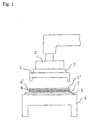
- 1 is a mold
- 2 is a heater
- 3 is an upper level block
- 4 is a lower level block
- 5 is a pad
- 6 and 6' are sheets or films to be sealed
- 7 and 7' are heat-resistant resin sheets
- 8 is a side opening of the file case
- 9 and 9' are top and bottom sealed sides
- 10 is another sealed side opposite to the opening.
- polyolefin resin films or sheets are sealed by sealing.
- the polyolefin resin includes polyethylene resins, polypropylene resins, and polyolefin resin compositions comprising them.
- the polyethylene resins include high-density polyethylene, low-density polyethylene, and linear ethylene- ⁇ -olefin copolymers. Of those, especially preferred are linear ethylene- ⁇ -olefin copolymers. As the copolymers, preferred are those having long-chain branches, such as ethylene-1-hexene copolymers and ethylene-1-octene copolymers. More preferably, the long-chain branches are randomly bonded to the main chain to give the chemical structure of the copolymers.
- the linear ethylene- ⁇ -olefin copolymers are prepared by copolymerizing ethylene with 1-hexene or the like, for example, in the presence of a so-called metallocene catalyst or geometrically-restrainable metallocene catalyst comprising, as the principal component, a complex with a transition metal such as titanium, zirconium or the like, and have a narrow molecular weight distribution.
- the polypropylene resins preferred are homopolypropylene, and also copolymers of propylene and ethylene, as well as copolymers of propylene, ethylene and 1-butene.
- the propylene-based copolymers have a comonomer, such as ethylene, content of from 0.1 to 10% by weight relative to propylene. More preferably, the comonomers are randomly bonded to the main chain of the copolymers.
- the polyolefin resin compositions comprise different types of polyethylene resins such as those mentioned above, different types of polypropylene resins such as those mentioned above, or a combination of such polyethylene resins and polypropylene resins, and may contain any ordinary fillers and improvers that are generally used for improving the physical properties of the resins.
- the proportions of those components constituting the compositions may be suitably determined in consideration of the mechanical strength and the design of the end-products of sealed articles.
- films or sheets of those polyolefin resins or their compositions may be prepared in any ordinary molding method.
- they may be prepared by extrusion molding through a T-die.
- the suitable range of the thickness of the polyolefin resin films to be worked according to the sealing method of the invention varies, depending on the type of the resins as well as on the molecular weight, the molecular weight distribution and the chemical structure of the polymer chain of the resins, but may fall generally between 20 and 200 ⁇ m, preferably between 50 and 150 ⁇ m.
- the thickness of the sheets may fall between 200 and 800 ⁇ m, preferably between 200 and 500 ⁇ m.
- thinner films and sheets than those falling within the defined ranges there will be some risk of their dielectric breakdown increasing.
- the mechanical strength of the sealed site will lower and the sealed site could hardly keep the original transparency, thereby resulting in that the outward appearance of the sealed articles is not good. For those reasons, such thinner or thicker films and sheets are unfavorable.
- Fig. 1 is a graphic view partly showing the mold section of a high-frequency dielectric heating device.
- the numeral reference 1 indicates a mold, which acts also as an upper electrode.
- the mold 1 is fixed to the upper level block 3 via a heater 2.
- Fig. 1, 4 is a lower level block, which acts also as a lower electrode.
- a plurality of films or sheets to be sealed, 6, 6' are set with their surfaces to be sealed facing each other.
- the films or sheets 6, 6' may be sandwiched between heat-resistant resin sheets 7, 7'.
- the pad 5, the films or sheets to be sealed, 6, 6', and the heat-resistant resin sheets 7, 7' are set in layers between the mold 1 and the lower level block 4, then a high-frequency field is applied between the mold 1 having been heated at a predetermined temperature and the lower level block 4, and the site to be sealed of the films or sheets 6, 6' is pressed against the pressing edges around the periphery of the mold 1, whereby it is sealed. Then, the high-frequency field is cut off. After having been cooled for a while, the mold 1 is opened, and the sealed article is taken out of it. Thus, the sealing process comprising the steps as above is finished.
- the error in the gap between the surface of the each pressing edge of the mold 1 and the surface of the lower level block 4 is controlled to fall within a range of ⁇ 100 ⁇ m.
- the degree of mutual inclination between the upper level block 3 and the lower level block 4 is controlled whereby the gap therebetween is unified, and, in addition, the gap error between the mold 1 and the upper level block 3 is controlled to fall within the range of ⁇ 100 ⁇ m, for example, by grinding and polishing the facing surfaces of the mold 1 and the upper level block 3.
- the thickness distribution in the site of the films or sheets to be sealed will increase, thereby often resulting in local increase in the voltage applied to the site over the dielectric breakdown voltage of the films or sheets being sealed. If so, the risk of sparking will increase.
- the mold 1 is heated by the heater 2 to be at a temperature ranging between 30°C and a temperature lower by 10°C than the melting point or the thermosoftening point of the films or sheets 6, 6'. If the heating temperature is lower than 30°C, the sealed site of the films or sheets 6, 6' could not have high mechanical strength and good transparency. If, on the other hand, the heating temperature is above the temperature that is lower by 10°C than the melting point of the thermosoftening point of the films or sheets 6, 6' being sealed, the sealed site will be deformed so that the outward appearance of the end-product, sealed article will be poor.
- the temperature of the pressing edges is so controlled that its error falls everywhere within a range of a predetermined temperature ⁇ 3°C.
- the temperature error in the pressing edges shall be so kept as not to overstep the range of a predetermined temperature ⁇ 3°C all the time during the sealing process, without being influenced by the ambient temperature change.
- the temperature distribution in the pressing edges shall be controlled to fall within the range of ⁇ 3°C all the time throughout the sealing process of heating the films or sheets for sealing them followed by cooling the sealed films or sheets, by controlling the contact between the mold 1 and the heater 2 so that all the pressing edges could uniformly receive and radiate heat.
- the temperature distribution in the pressing edges of the mold 1 oversteps the range of ⁇ 3°C somewhere in the edges, the reduction in the films or sheets having been sealed under heat and pressure at the edges will fluctuate, thereby causing a flow of overvoltage passing through the sealed site. In that case, the voltage will be over the dielectric breakdown voltage of the films or sheets to cause sparking. In addition, if the temperature of the pressing edges greatly fluctuates during the sealing process, the temperature fluctuation will bring about a flow of overvoltage passing through the site of the films or sheets being sealed, thereby also causing sparking at the site.
- the pad 5 to be used herein may be of a film, sheet or plate of a material having a dielectric loss coefficient of at least 0.01 at 23°C at 1 MHz.
- the thickness of the pad 5 falls between 0.05 and 5.0 mm, more preferably between 0.1 and 2.0 mm.
- the material for the pad 5 includes, for example, organic materials, inorganic materials, and composite materials containing inorganic materials.
- the organic materials include phenolic resins, epoxy resins, polyvinyl formal resins, polychloroprene resins, urea resins, melamine-formaldehyde resins, polycarbonate resins, polymethyl methacrylate resins, aramide resins, polyamide resins, polyamidimide resins, polyvinylidene chloride resins, melamine resins, polysulfone resins, chlorosulfonated polyethylene resins, chlorinated polyethylene resins, etc.
- the inorganic materials include, for example, spinel (MgO.Al 2 O 3 ), mullite, (3Al 2 O 3 .SiO 2 ), titania (TiO 2 ) and other ceramics.
- Preferred examples of the composite materials are moldings of inorganic filler-containing phenolic resins, laminates of epoxy resin-infiltrated glass fibers, moldings of carbon fiber-reinforced resins, varnish clothes, etc.
- the heat-resistant resin sheets 7, 7' which are optionally used for sandwiching the films or sheets 6, 6' between them, are preferably sheets of polyethylene terephthalate resins, polycarbonate resins, polyethersulfone resins, polyimide resins or the like, and their thickness may fall between 10 and 100 microns.
- the heat-resistant resin sheets 7, 7' may be placed on either one surface or both surfaces of the films or sheets 6, 6', whereby their smooth surfaces are transferred onto the surfaces of the films or sheets 6, 6' being sealed. As a result, the surface gloss of the sealed site of the films or sheets 6, 6' is increased and the sealed article could have good appearance.
- a high-frequency field is applied to the films or sheets 6, 6' being pressed.
- the high-frequency field may range between 1 and 300 MHz.
- an ordinary high-frequency dielectric heating device that may generate high-frequency waves of 27.12 MHz or 40.46 MHz.
- the high-frequency field is applied to the films or sheets 6, 6' being sealed, in such a manner that no-load current is first applied to the films or sheets 6, 6' at the start of applying the high-frequency field to them, and thereafter the voltage for the current to them is increased up to a level lower than 95 % of the dielectric breakdown voltage of the films or sheets 6, 6' thereby to attain the intended high-frequency dielectric heating of the films or sheets 6, 6'.
- the high-frequency dielectric heating device to be used for this may be such that the capacitance of the variable capacitor in the matching circuit as connected with the high-frequency power source for it is previously computed as a function to the current to be applied to the device (for example, an automatic tuning device).
- no-load current is first applied to the films or sheets 6, 6' at the start of applying the high-frequency field to them. This is in order to evade the dielectric breakdown of the films or sheets 6, 6' that may be caused by sparking.
- the films or sheets 6, 6' absorb the power and generate heat, and the high-frequency loss coefficient of the films or sheets 6, 6' has a positive temperature characteristic to increase with their temperature rising. Therefore, if large power is applied to the films or sheets 6, 6' in the initial stage while their temperature is still low, the voltage between the two electrodes between which the films and sheets 6, 6' are put will be too great to evade the risk of sparking.
- the current to them is controlled at a level lower than 95 % of the dielectric breakdown voltage of the films or sheets 6, 6' thereby to evade the dielectric breakdown of the films or sheets 6, 6'.
- the optimum value of the current to be applied to the films or sheets 6, 6' under that condition shall be determined, depending on the type and the thickness of the films or sheets 6, 6' and on their area to be sealed. In general, the current may fall between 0.2 and 5 A, preferably between 0.2 and 2 A. If it is lower than the defined range, the risk of sparking between the electrodes will increase; but if higher, the appearance of the sealed site will be not good.
- the time for the high-frequency field application shall also be determined, depending on the type and the thickness of the films or sheets 6, 6' and on their area to be sealed. In general, the time may fall between 0.5 and 10 seconds, preferably between 1 and 6 seconds, more preferably between 1 and 4 seconds.
- the time for power application for the high-frequency dielectric heating may fall between 0.5 and 10 times, preferably between 1 and 5 seconds, more preferably between 1 and 3 seconds.
- the cooling time may fall between 0.5 and 10 seconds, preferably between 1 and 5 seconds, more preferably between 1 and 3 seconds.
- pressure is applied between the mold 1 and the lower level block 4.
- the pressure shall be determined, depending on the type and the thickness of the films or sheets 6, 6' and on their area to be sealed. Suitably, in general, it may fall between 0.5 and 5 kg/cm 2 . If the pressure is lower than the defined range, the electrodes will spark; but if higher, the risk of poor appearance of the sealed articles will increase.
- the sealed site has an extremely high sealing strength over a level of 25 N/15 mm width, which could not be realized by any other sealed articles as produced in conventional high-frequency dielectric heating methods.
- the white light transmittance of the sealed site of the sealed articles of the invention is at least over 50 %.
- the appearance of the sealed articles of the invention is much superior to that of conventional ones in that, in the former, the transparency of the sealed site could not be differentiated at a glance from that of the non-sealed site.
- the sealing strength mentioned above indicates the peeling strength of the sealed site, which is measured as follows: The sealed site of a sealed article to be measured is cut into a test piece having a width of 15 mm, and peeled at 90 degrees at a stress rate of 300 mm/min, using a tensile tester, and the force needed for peeling it is measured.
- the light transmittance referred to herein is measured, using a haze tester, in accordance with JIS-K-7105. For this, white light is irradiated to a sealed article to be measured, in the direction vertical to the sealed surface of the article, and the amount of light transmittance through the sealed site is measured.
- the sealed articles of the invention have many applications in various fields. For example, they can be used as stationery such as card cases, book cases, files, name holders, etc.; packaging containers for toys, eyedroppers, etc.; daily necessities such as rain things, bags, etc.; as well as other various wrapping or packaging materials.
- stationery such as card cases, book cases, files, name holders, etc.
- daily necessities such as rain things, bags, etc.
- other various wrapping or packaging materials are described in more detail with reference to the following Examples, which, however, are not intended to restrict the scope of the invention.
- a polyolefin resin composition as prepared by melting and kneading a mixture of 20 % by weight of homopolypropylene and 80 % by weight of ethylene-1-octene copolymer with a linear molecular structure (1-octene content: 9.5 % by weight) was extruded into a sheet [A], which was used herein for sealing.
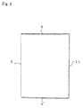
- the sheet [A] had a thickness of 200 ⁇ m, a length of 330 mm and a width of 240 mm. Two sheets [A] were placed one upon another, and three of the four edges of the piled sheets were sealed to give a file case of Fig. 2.
- the high-frequency dielectric heating device of Fig. 1 was used for sealing the sheets [A], in which the mold 1 was fixed to the upper level block 3 via the heater 2, and the lower level block 4 was set below the mold 1.
- the error in the gas between the upper level block 3 and the lower level block 4 was controlled to be ⁇ 30 ⁇ m everywhere between them.
- the surface of the mold 1 at which it is fixed to the upper level block 3 was polished so that the error in the gap between the surface and the pressing edge of the mold 1 was controlled to be ⁇ 30 ⁇ m.
- a varnish cloth (Empire Cloth (trade name) 0.21 mm thick) having a dielectric loss coefficient of 0.079 at 23°C at 1 MHz was put on the lower level block 4, and two sheets [A], 6, 6' were put on the pad 5, while being sandwiched between heat-resistant polyethylene terephthalate resin films 7, 7' (thickness: 25 ⁇ m each) thereon.
- the mold 1 had pressing edges (width: 3 mm each) on its pressing surface, facing the periphery of the sheets 6, 6' in two lengthwise directions and in one widthwise direction.
- the mold 1 was heated with the heater 2 fixed to the upper level block 3 in the high-frequency dielectric heating device.
- the temperature of the tip of each pressing edge was controlled to be 98°C. Two hours and 4 hours after the start of heating the mold 1, the temperature distribution in the tip of each pressing edge was measured, and it fell within the range of 98°C ⁇ 2°C everywhere in the places measured.
- the pressure of the mold 1 to the sheets 6, 6' was controlled to be 4.1 kg/cm 2 G, and kept as it was for 0.5 seconds, and thereafter a high-frequency field of 40.46 MHz was applied to the sheets.
- the current for the high-frequency dielectric heating was first controlled to be 0.3 A (no-load current) at the start of the heating, and thereafter increased up to 0.55 A over a period of 3 seconds. Then, the current of 0.55 A was kept as such for further 2 seconds. The total time of current application was 5 seconds. After the high-frequency dielectric heating step, the sheets were kept cooled for 2 seconds, and then the mold 1 was opened to remove the pressure therein, and thereafter the sealed article was taken out of the mold 1.
- the file case of Fig. 2 was produced.
- the numeral reference 8 indicates a side opening for papers and others to be therein
- 9 and 9' indicate top and bottom sealed sides
- 10 indicates another sealed side opposite to the opening.
- the width of those sealed sides was 3 mm each.
- shown are the boundaries between the sealed site and the non-sealed site, which, however, are only for the drawing convenience. In fact, in the outward appearance of the file case produced herein, there was found no substantial difference in the transparency between the sealed site and the non-sealed site.
- the file case was cut into a test piece of 15 mm width including the sealed site.
- the sealed site of the test piece was peeled at a stress rate of 300 mm/min at an angle of 90 degrees, and the force needed for peeling it (sealing strength) was measured.
- Another test piece including the sealed site was cut out.
- White light was irradiated to it, and the percentage of the light having passed through the sealed site (light transmittance) was measured, using a haze tester, in accordance with JIS-K-7105. The data obtained are shown in Table 1.
- Sheets [A] having the same composition as in Example 1 were used as the sheets to be sealed herein.
- the temperature of the tip of each pressing edges of the mold 1 was controlled to be 110°C.
- Two hours and 5 hours after the start of heating the mold 1 the temperature distribution in the tip of each pressing edge was measured, and it fell within the range of 110°C ⁇ 2°C everywhere in the places measured.
- the sheets were sealed in the same manner as in Example 1 to produce a file case, except that the pressure of the mold 1 to the sheets was controlled to be 3.4 kg/cm 2 and the time for current application was 7.5 seconds.
- the sealing strength and the light transmittance of the file case were measured.
- the data obtained are in Table 1.
- the temperature of the tip of each pressing edges of the mold 1 was controlled to be 110°C. Two hours and 5 hours after the start of heating the mold 1, the temperature distribution in the tip of each pressing edge was measured, and it fell within the range of 110°C ⁇ 2°C everywhere in the places measured.
- the sheets were sealed in the same manner as in Example 1 to produce a file case, except that the pressure of the mold 1 to the sheets was controlled to be 3.4 kg/cm 2 , the current applied was 0.5 A and the time for current application was 5.5 seconds. The sealing strength and the light transmittance of the file case were measured. The data obtained are in Table 1.
- Sheets [B] having the same composition as in Example 3 were used as the sheets to be sealed herein.
- the temperature of the tip of each pressing edges of the mold 1 was controlled to be 120°C. Two hours and 5 hours after the start of heating the mold 1, the temperature distribution in the tip of each pressing edge was measured, and it fell within the range of 120°C ⁇ 2°C everywhere in the places measured.
- the sheets were sealed in the same manner as in Example 3 to produce a file case, except that the pressure of the mold 1 to the sheets was controlled to be 4.1 kg/cm 2 and the time for current application was 4 seconds. The sealing strength and the light transmittance of the file case were measured. The data obtained are in Table 1.
- the temperature of the tip of each pressing edges of the mold 1 was controlled to be 100°C. Two hours and 5 hours after the start of heating the mold 1, the temperature distribution in the tip of each pressing edge was measured, and it fell within the range of 100°C ⁇ 2°C everywhere in the places measured.
- the sheets were sealed in the same manner as in Example 1 to produce a file case, except that the pressure of the mold 1 to the sheets was controlled to be 4.1 kg/cm 2 and the current applied was 0.5 A. The sealing strength and the light transmittance of the file case were measured. The data obtained are in Table 1.
- Sheets [C] having the same composition as in Example 5 were used as the sheets to be sealed herein.
- the temperature of the tip of each pressing edges of the mold 1 was controlled to be 110°C.
- Two hours and 5 hours after the start of heating the mold 1 the temperature distribution in the tip of each pressing edge was measured, and it fell within the range of 110°C ⁇ 2°C everywhere in the places measured.
- the sheets were sealed in the same manner as in Example 5 to produce a file case, except that the pressure of the mold 1 to the sheets was controlled to be 3.4 kg/cm 2 and the time for current application was 7.5 seconds.
- the sealing strength and the light transmittance of the file case were measured.
- the data obtained are in Table 1.
- the thickness of the interlayer was 80 microns, and that of the outer layers was 60 microns each.
- the temperature of the tip of each pressing edges of the mold 1 was controlled to be 110°C. Two hours and 5 hours after the start of heating the mold 1, the temperature distribution in the tip of each pressing edge was measured, and it fell within the range of 110°C ⁇ 2°C everywhere in the places measured.
- the sheets were sealed in the same manner as in Example 1 to produce a file case, except that the pressure of the mold 1 to the sheets was controlled to be 3.4 kg/cm 2 , the current applied was 0.5 A and the time for current application was 7.5 seconds. The sealing strength and the light transmittance of the file case were measured. The data obtained are in Table 1.
- Layered sheets [D] having the same composition as in Example 7 were used as the sheets to be sealed herein.
- the temperature of the tip of each pressing edges of the mold 1 was controlled to be 120°C. Two hours and 5 hours after the start of heating the mold 1, the temperature distribution in the tip of each pressing edge was measured, and it fell within the range of 120°C ⁇ 2°C everywhere in the places measured.
- the sheets were sealed in the same manner as in Example 7 to produce a file case, except that the pressure of the mold 1 to the sheets was controlled to be 4.1 kg/cm 2 and the time for current application was 4 seconds. The sealing strength and the light transmittance of the file case were measured. The data obtained are in Table 1.
- the thickness of the interlayer was 180 microns, and that of the outer layers was 60 microns each.
- the temperature of the tip of each pressing edges of the mold 1 was controlled to be 110°C. Two hours and 5 hours after the start of heating the mold 1, the temperature distribution in the tip of each pressing edge was measured, and it fell within the range of 110°C ⁇ 2°C everywhere in the places measured.
- the sheets were sealed in the same manner as in Example 1 to produce a file case, except that the pressure of the mold 1 to the sheets was controlled to be 3.4 kg/cm 2 , the current applied was 0.35 A and the time for current application was 5.5 seconds. The sealing strength and the light transmittance of the file case were measured. The data obtained are in Table 1.
- Layered sheets [E] having the same composition as in Example 9 were used as the sheets to be sealed herein.
- the temperature of the tip of each pressing edges of the mold 1 was controlled to be 120°C. Two hours and 5 hours after the start of heating the mold 1, the temperature distribution in the tip of each pressing edge was measured, and it fell within the range of 120°C ⁇ 2°C everywhere in the places measured.
- the sheets were sealed in the same manner as in Example 9 to produce a file case, except that the pressure of the mold 1 to the sheets was controlled to be 4.1 kg/cm 2 and the time for current application was 4 seconds. The sealing strength and the light transmittance of the file case were measured. The data obtained are in Table 1.
- the thickness of the interlayer was 260 microns, and that of the outer layers was 20 microns each.
- the pad 5 the same Bakelite plate as in Example 9 was used.
- the temperature of the tip of each pressing edges of the mold 1 was controlled to be 120°C. Two hours and 5 hours after the start of heating the mold 1, the temperature distribution in the tip of each pressing edge was measured, and it fell within the range of 120°C ⁇ 2°C everywhere in the places measured.
- the sheets were sealed in the same manner as in Example 1 to produce a file case, except that the pressure of the mold 1 to the sheets was controlled to be 3.4 kg/cm 2 , the current applied was 0.35 A and the time for current application was 5.5 seconds. The sealing strength and the light transmittance of the file case were measured. The data obtained are in Table 1.
- Layered sheets [E'] having the same composition as in Example 11 were used as the sheets to be sealed herein.
- the temperature of the tip of each pressing edges of the mold 1 was controlled to be 120°C. Two hours and 5 hours after the start of heating the mold 1, the temperature distribution in the tip of each pressing edge was measured, and it fell within the range of 120°C ⁇ 2°C everywhere in the places measured.
- the sheets were sealed in the same manner as in Example 11 to produce a file case, except that the pressure of the mold 1 to the sheets was controlled to be 4.1 kg/cm 2 and the time for current application was 4 seconds. The sealing strength and the light transmittance of the file case were measured. The data obtained are in Table 1.
- the thickness of the interlayer was 200 microns, and that of the outer layers was 50 microns each.
- the pad 5 the same Bakelite plate as in Example 9 was used.
- the temperature of the tip of each pressing edges of the mold 1 was controlled to be 110°C. Two hours and 5 hours after the start of heating the mold 1, the temperature distribution in the tip of each pressing edge was measured, and it fell within the range of 110°C ⁇ 2°C everywhere in the places measured.
- the sheets were sealed in the same manner as in Example 1 to produce a file case, except that the pressure of the mold 1 to the sheets was controlled to be 3.4 kg/cm 2 , the current applied was 0.35 A and the time for current application was 5.5 seconds. The sealing strength and the light transmittance of the file case were measured. The data obtained are in Table 1.
- Layered sheets [F] having the same composition as in Example 13 were used as the sheets to be sealed herein.
- the temperature of the tip of each pressing edges of the mold 1 was controlled to be 120°C. Two hours and 5 hours after the start of heating the mold 1, the temperature distribution in the tip of each pressing edge was measured, and it fell within the range of 120°C ⁇ 2°C everywhere in the places measured.
- the sheets were sealed in the same manner as in Example 13 to produce a file case, except that the pressure of the mold 1 to the sheets was controlled to be 4.1 kg/cm 2 and the time for current application was 4 seconds. The sealing strength and the light transmittance of the file case were measured. The data obtained are in Table 1.
- a composition comprising a mixture of 70 % by weight of polypropylene with low stereospecificity (its stereospecificity was 24.2 % relative to the pentad fraction and it has a boiling heptane-insoluble content of 90% by weight) and 30 % by weight of hydrogenated styrene-butadiene rubber was molded into a sheet [H], which was used herein for sealing.
- the thickness of the sheet [H] was 200 microns.
- the pad 5 the same Bakelite plate as in Example 9 was used.
- the temperature of the tip of each pressing edges of the mold 1 was controlled to be 110°C. Two hours and 5 hours after the start of heating the mold 1, the temperature distribution in the tip of each pressing edge was measured, and it fell within the range of 110°C ⁇ 2°C everywhere in the places measured.
- the sheets were sealed in the same manner as in Example 1 to produce a file case, except that the pressure of the mold 1 to the sheets was controlled to be 3.4 kg/cm 2 , the current applied was 0.35 A and the time for current application was 5.5 seconds. The sealing strength and the light transmittance of the file case were measured. The data obtained are in Table 1.
- Sheets [H] having the same composition as in Example 15 were used as the sheets to be sealed herein.
- the temperature of the tip of each pressing edges of the mold 1 was controlled to be 120°C.
- Two hours and 5 hours after the start of heating the mold 1 the temperature distribution in the tip of each pressing edge was measured, and it fell within the range of 120°C ⁇ 2°C everywhere in the places measured.
- the sheets were sealed in the same manner as in Example 13 to produce a file case, except that the pressure of the mold 1 to the sheets was controlled to be 4.1 kg/cm 2 and the time for current application was 4 seconds.
- the sealing strength and the light transmittance of the file case were measured.
- the data obtained are in Table 1.
- Example 1 Sealing Strength (N/15 mm width) Light Transmittance at Sealed Site (%) Example 1 30 70 Example 2 29 85 Example 3 32 85 Example 4 26 80 Example 5 28 85 Example 6 28 75 Example 7 29 65 Example 8 28 75 Example 9 30 70 Example 10 30 75 Example 11 32 80 Example 12 33 90 Example 13 30 70 Example 14 30 75 Example 15 32 80 Example 16 33 90
- sealed articles are stably produced with no sparking, and the sealed articles produced have extremely high mechanical strength and high transparency at the sealed site.
Applications Claiming Priority (2)
| Application Number | Priority Date | Filing Date | Title |
|---|---|---|---|
| JP7715698A JPH11268134A (ja) | 1998-03-25 | 1998-03-25 | ポリオレフィン系樹脂の融着加工法および融着加工製品 |
| JP7715698 | 1998-03-25 |
Publications (2)
| Publication Number | Publication Date |
|---|---|
| EP0945247A2 true EP0945247A2 (fr) | 1999-09-29 |
| EP0945247A3 EP0945247A3 (fr) | 2001-04-11 |
Family
ID=13625941
Family Applications (1)
| Application Number | Title | Priority Date | Filing Date |
|---|---|---|---|
| EP99105321A Withdrawn EP0945247A3 (fr) | 1998-03-25 | 1999-03-16 | Soudage de matières synthétiques à base de polyoléfines et article soudé |
Country Status (3)
| Country | Link |
|---|---|
| US (1) | US6162320A (fr) |
| EP (1) | EP0945247A3 (fr) |
| JP (1) | JPH11268134A (fr) |
Cited By (1)
| Publication number | Priority date | Publication date | Assignee | Title |
|---|---|---|---|---|
| EP2724840A1 (fr) * | 2012-10-25 | 2014-04-30 | ROPEX Industrie-Elektronik GmbH | Dispositif de soudage et procédé de soudage d'au moins deux couches de matériau d'une pièce usinée |
Families Citing this family (4)
| Publication number | Priority date | Publication date | Assignee | Title |
|---|---|---|---|---|
| WO2001054460A1 (fr) * | 2000-01-21 | 2001-07-26 | Idemitsu Petrochemical Co., Ltd. | Materiau inorganique pour application de chauffage par induction haute frequence, materiau composite, moule et procede de production d'articles traites par fusion haute frequence |
| CN103286945B (zh) * | 2013-05-17 | 2016-05-11 | 刘炜舜 | 一种焊接效果好的焊接装置 |
| CN106393708B (zh) * | 2016-11-30 | 2018-07-13 | 蓝思科技(长沙)有限公司 | 一种贴胶装夹治具以及贴胶工艺 |
| CN114030272A (zh) * | 2021-11-04 | 2022-02-11 | 中国电子科技集团公司第三十八研究所 | 提高浮空器囊体材料热合可靠性的方法 |
Citations (10)
| Publication number | Priority date | Publication date | Assignee | Title |
|---|---|---|---|---|
| BE485212A (fr) * | 1900-01-01 | |||
| US2667437A (en) * | 1949-10-11 | 1954-01-26 | Swift & Co | Method of sealing polyethylene films |
| US2747646A (en) * | 1955-10-26 | 1956-05-29 | Lippman Gerald | Process of and apparatus for producing applique ornamentations |
| GB781444A (en) * | 1952-10-13 | 1957-08-21 | Vickers Electrical Co Ltd | Improvements relating to high frequency electrical generators for dielectric heating |
| US2842649A (en) * | 1957-01-16 | 1958-07-08 | Jehier Andre | Machine for welding plastic sheet materials |
| FR1206649A (fr) * | 1958-01-28 | 1960-02-10 | Procédé et appareil pour la soudure de feuilles en une matière thermoplastique telle que le polyéthylène | |
| US4950347A (en) * | 1986-01-12 | 1990-08-21 | Nissho Corporation | Method for welding thermoplastic resin |
| GB2244236A (en) * | 1990-06-06 | 1991-11-27 | Casey Technology Limited | A method and apparatus for sealing |
| EP0546502A2 (fr) * | 1991-12-09 | 1993-06-16 | W.R. Grace & Co.-Conn. | Procédé et appareil à haute fréquence pour le sondage de films en matière thermoplastique |
| US5366580A (en) * | 1992-01-08 | 1994-11-22 | Cosmos Electronic Machine Corp. | High frequency welding machine |
Family Cites Families (6)
| Publication number | Priority date | Publication date | Assignee | Title |
|---|---|---|---|---|
| IT1125919B (it) * | 1978-12-14 | 1986-05-14 | Tachikawa Spring Co | Metodo e apparecchiatura per la rpoduzione di cuscini di sedile e prodotti con cio' ottenuti |
| JPS59199461A (ja) * | 1983-04-23 | 1984-11-12 | テルモ株式会社 | 包装容器およびその密封方法 |
| JPS63242627A (ja) * | 1987-03-31 | 1988-10-07 | Popii Sangyo Kk | 高周波ウエルダ |
| JPS63288738A (ja) * | 1987-05-20 | 1988-11-25 | Tonen Sekiyukagaku Kk | 高周波溶着方法 |
| JPH01198327A (ja) * | 1988-02-04 | 1989-08-09 | Toyota Motor Corp | 高周波溶接方法 |
| JP2782415B2 (ja) * | 1994-08-12 | 1998-07-30 | 株式会社ピアレス | 高周波誘電加熱によるプラスチックの接着法 |
-
1998
- 1998-03-25 JP JP7715698A patent/JPH11268134A/ja not_active Withdrawn
-
1999
- 1999-03-10 US US09/265,595 patent/US6162320A/en not_active Expired - Fee Related
- 1999-03-16 EP EP99105321A patent/EP0945247A3/fr not_active Withdrawn
Patent Citations (10)
| Publication number | Priority date | Publication date | Assignee | Title |
|---|---|---|---|---|
| BE485212A (fr) * | 1900-01-01 | |||
| US2667437A (en) * | 1949-10-11 | 1954-01-26 | Swift & Co | Method of sealing polyethylene films |
| GB781444A (en) * | 1952-10-13 | 1957-08-21 | Vickers Electrical Co Ltd | Improvements relating to high frequency electrical generators for dielectric heating |
| US2747646A (en) * | 1955-10-26 | 1956-05-29 | Lippman Gerald | Process of and apparatus for producing applique ornamentations |
| US2842649A (en) * | 1957-01-16 | 1958-07-08 | Jehier Andre | Machine for welding plastic sheet materials |
| FR1206649A (fr) * | 1958-01-28 | 1960-02-10 | Procédé et appareil pour la soudure de feuilles en une matière thermoplastique telle que le polyéthylène | |
| US4950347A (en) * | 1986-01-12 | 1990-08-21 | Nissho Corporation | Method for welding thermoplastic resin |
| GB2244236A (en) * | 1990-06-06 | 1991-11-27 | Casey Technology Limited | A method and apparatus for sealing |
| EP0546502A2 (fr) * | 1991-12-09 | 1993-06-16 | W.R. Grace & Co.-Conn. | Procédé et appareil à haute fréquence pour le sondage de films en matière thermoplastique |
| US5366580A (en) * | 1992-01-08 | 1994-11-22 | Cosmos Electronic Machine Corp. | High frequency welding machine |
Non-Patent Citations (4)
| Title |
|---|
| PATENT ABSTRACTS OF JAPAN vol. 013, no. 033 (M-789), 25 January 1989 (1989-01-25) & JP 63 242627 A (POPII SANGYO KK), 7 October 1988 (1988-10-07) * |
| PATENT ABSTRACTS OF JAPAN vol. 013, no. 100 (M-805), 9 March 1989 (1989-03-09) & JP 63 288738 A (TONEN SEKIYUKAGAKU KK), 25 November 1988 (1988-11-25) * |
| PATENT ABSTRACTS OF JAPAN vol. 013, no. 497 (M-889), 9 November 1989 (1989-11-09) & JP 01 198327 A (TOYOTA MOTOR CORP;OTHERS: 01), 9 August 1989 (1989-08-09) * |
| PATENT ABSTRACTS OF JAPAN vol. 1996, no. 06, 28 June 1996 (1996-06-28) & JP 08 052802 A (PIARESU:KK;OTHERS: 01), 27 February 1996 (1996-02-27) * |
Cited By (1)
| Publication number | Priority date | Publication date | Assignee | Title |
|---|---|---|---|---|
| EP2724840A1 (fr) * | 2012-10-25 | 2014-04-30 | ROPEX Industrie-Elektronik GmbH | Dispositif de soudage et procédé de soudage d'au moins deux couches de matériau d'une pièce usinée |
Also Published As
| Publication number | Publication date |
|---|---|
| US6162320A (en) | 2000-12-19 |
| JPH11268134A (ja) | 1999-10-05 |
| EP0945247A3 (fr) | 2001-04-11 |
Similar Documents
| Publication | Publication Date | Title |
|---|---|---|
| TWI643747B (zh) | 延伸聚丙烯積層膜 | |
| CN109070568B (zh) | 双轴拉伸层叠聚丙烯薄膜 | |
| KR910009524B1 (ko) | 열융착성 폴리에틸렌 가교연신필름과 그의 제조방법 | |
| TWI414554B (zh) | 薄膜及離型薄膜 | |
| KR102349685B1 (ko) | 폴리프로필렌 필름 및 이형용 필름 | |
| US6271155B1 (en) | Composite sheet comprising a non-woven fabric and a film | |
| CN1068015C (zh) | 改进的丙烯共聚物热密封树脂及其制品 | |
| EP1780009B1 (fr) | Matériau multicouche | |
| JP6090137B2 (ja) | 二軸延伸ポリプロピレンフィルム | |
| WO1982000020A1 (fr) | Lamines de polyethylene/metal et leurs procedes de fabrication | |
| KR20120059499A (ko) | 다중층 폴리프로필렌 필름과 이를 제조하고 사용하는 방법 | |
| KR102593205B1 (ko) | 폴리프로필렌계 적층 필름 | |
| CN112888729B (zh) | 聚丙烯膜及脱模膜 | |
| US5318824A (en) | Packaging structure | |
| US6162320A (en) | Sealing of polyolefin-based resin and sealed article of the resin | |
| EP2639062A1 (fr) | Film composite de polyoléfine | |
| EP0554450A1 (fr) | Film stratifie a trois couches | |
| JP2010024354A (ja) | 二軸延伸ポリプロピレンフィルム及びその用途 | |
| Yue et al. | The morphology, character and strength of the interface in glass fibre-polypropylene composites | |
| JP7070426B2 (ja) | 積層ポリプロピレンフィルム | |
| JP2005280125A (ja) | 離型用ポリプロピレンフィルム | |
| JPH04136037A (ja) | 超高分子量ポリエチレン層の相互接着方法 | |
| CN104520362B (zh) | 模内标签用聚丙烯薄膜 | |
| US4973375A (en) | Process for producing a composite sheet | |
| JPH0373452B2 (fr) |
Legal Events
| Date | Code | Title | Description |
|---|---|---|---|
| PUAI | Public reference made under article 153(3) epc to a published international application that has entered the european phase |
Free format text: ORIGINAL CODE: 0009012 |
|
| AK | Designated contracting states |
Kind code of ref document: A2 Designated state(s): DE FR GB |
|
| AX | Request for extension of the european patent |
Free format text: AL;LT;LV;MK;RO;SI |
|
| PUAL | Search report despatched |
Free format text: ORIGINAL CODE: 0009013 |
|
| AK | Designated contracting states |
Kind code of ref document: A3 Designated state(s): AT BE CH CY DE DK ES FI FR GB GR IE IT LI LU MC NL PT SE |
|
| AX | Request for extension of the european patent |
Free format text: AL;LT;LV;MK;RO;SI |
|
| 17P | Request for examination filed |
Effective date: 20010917 |
|
| AKX | Designation fees paid |
Free format text: DE FR GB |
|
| 17Q | First examination report despatched |
Effective date: 20020712 |
|
| STAA | Information on the status of an ep patent application or granted ep patent |
Free format text: STATUS: THE APPLICATION IS DEEMED TO BE WITHDRAWN |
|
| 18D | Application deemed to be withdrawn |
Effective date: 20021123 |