EP0944937B1 - Hydraulisches pressgerät - Google Patents
Hydraulisches pressgerät Download PDFInfo
- Publication number
- EP0944937B1 EP0944937B1 EP98951524A EP98951524A EP0944937B1 EP 0944937 B1 EP0944937 B1 EP 0944937B1 EP 98951524 A EP98951524 A EP 98951524A EP 98951524 A EP98951524 A EP 98951524A EP 0944937 B1 EP0944937 B1 EP 0944937B1
- Authority
- EP
- European Patent Office
- Prior art keywords
- valve
- pressing device
- piston
- valve piston
- return
- Prior art date
- Legal status (The legal status is an assumption and is not a legal conclusion. Google has not performed a legal analysis and makes no representation as to the accuracy of the status listed.)
- Expired - Lifetime
Links
- 238000003825 pressing Methods 0.000 title claims abstract description 50
- 230000006835 compression Effects 0.000 claims description 3
- 238000007906 compression Methods 0.000 claims description 3
- 230000000149 penetrating effect Effects 0.000 claims description 2
- 238000000034 method Methods 0.000 abstract description 7
- 238000007789 sealing Methods 0.000 description 7
- 230000008569 process Effects 0.000 description 6
- 230000008901 benefit Effects 0.000 description 5
- 230000000694 effects Effects 0.000 description 5
- 239000004020 conductor Substances 0.000 description 3
- 238000013016 damping Methods 0.000 description 3
- 238000006073 displacement reaction Methods 0.000 description 3
- 230000005540 biological transmission Effects 0.000 description 2
- 238000005516 engineering process Methods 0.000 description 2
- 230000009467 reduction Effects 0.000 description 2
- 230000004044 response Effects 0.000 description 2
- 238000003860 storage Methods 0.000 description 2
- 230000001960 triggered effect Effects 0.000 description 2
- 230000009471 action Effects 0.000 description 1
- 230000015572 biosynthetic process Effects 0.000 description 1
- 230000007423 decrease Effects 0.000 description 1
- 230000003247 decreasing effect Effects 0.000 description 1
- 230000002349 favourable effect Effects 0.000 description 1
- 238000005304 joining Methods 0.000 description 1
- 238000004519 manufacturing process Methods 0.000 description 1
- 230000003287 optical effect Effects 0.000 description 1
- 230000036316 preload Effects 0.000 description 1
- 238000010992 reflux Methods 0.000 description 1
- 230000008439 repair process Effects 0.000 description 1
- 238000000926 separation method Methods 0.000 description 1
Images


Classifications
-
- B—PERFORMING OPERATIONS; TRANSPORTING
- B25—HAND TOOLS; PORTABLE POWER-DRIVEN TOOLS; MANIPULATORS
- B25B—TOOLS OR BENCH DEVICES NOT OTHERWISE PROVIDED FOR, FOR FASTENING, CONNECTING, DISENGAGING OR HOLDING
- B25B27/00—Hand tools, specially adapted for fitting together or separating parts or objects whether or not involving some deformation, not otherwise provided for
- B25B27/02—Hand tools, specially adapted for fitting together or separating parts or objects whether or not involving some deformation, not otherwise provided for for connecting objects by press fit or detaching same
- B25B27/10—Hand tools, specially adapted for fitting together or separating parts or objects whether or not involving some deformation, not otherwise provided for for connecting objects by press fit or detaching same inserting fittings into hoses
-
- B—PERFORMING OPERATIONS; TRANSPORTING
- B21—MECHANICAL METAL-WORKING WITHOUT ESSENTIALLY REMOVING MATERIAL; PUNCHING METAL
- B21D—WORKING OR PROCESSING OF SHEET METAL OR METAL TUBES, RODS OR PROFILES WITHOUT ESSENTIALLY REMOVING MATERIAL; PUNCHING METAL
- B21D39/00—Application of procedures in order to connect objects or parts, e.g. coating with sheet metal otherwise than by plating; Tube expanders
- B21D39/04—Application of procedures in order to connect objects or parts, e.g. coating with sheet metal otherwise than by plating; Tube expanders of tubes with tubes; of tubes with rods
-
- B—PERFORMING OPERATIONS; TRANSPORTING
- B21—MECHANICAL METAL-WORKING WITHOUT ESSENTIALLY REMOVING MATERIAL; PUNCHING METAL
- B21J—FORGING; HAMMERING; PRESSING METAL; RIVETING; FORGE FURNACES
- B21J15/00—Riveting
- B21J15/10—Riveting machines
- B21J15/16—Drives for riveting machines; Transmission means therefor
- B21J15/20—Drives for riveting machines; Transmission means therefor operated by hydraulic or liquid pressure
-
- B—PERFORMING OPERATIONS; TRANSPORTING
- B21—MECHANICAL METAL-WORKING WITHOUT ESSENTIALLY REMOVING MATERIAL; PUNCHING METAL
- B21J—FORGING; HAMMERING; PRESSING METAL; RIVETING; FORGE FURNACES
- B21J15/00—Riveting
- B21J15/10—Riveting machines
- B21J15/16—Drives for riveting machines; Transmission means therefor
- B21J15/26—Drives for riveting machines; Transmission means therefor operated by rotary drive, e.g. by electric motor
-
- B—PERFORMING OPERATIONS; TRANSPORTING
- B25—HAND TOOLS; PORTABLE POWER-DRIVEN TOOLS; MANIPULATORS
- B25F—COMBINATION OR MULTI-PURPOSE TOOLS NOT OTHERWISE PROVIDED FOR; DETAILS OR COMPONENTS OF PORTABLE POWER-DRIVEN TOOLS NOT PARTICULARLY RELATED TO THE OPERATIONS PERFORMED AND NOT OTHERWISE PROVIDED FOR
- B25F5/00—Details or components of portable power-driven tools not particularly related to the operations performed and not otherwise provided for
- B25F5/005—Hydraulic driving means
-
- H—ELECTRICITY
- H01—ELECTRIC ELEMENTS
- H01R—ELECTRICALLY-CONDUCTIVE CONNECTIONS; STRUCTURAL ASSOCIATIONS OF A PLURALITY OF MUTUALLY-INSULATED ELECTRICAL CONNECTING ELEMENTS; COUPLING DEVICES; CURRENT COLLECTORS
- H01R43/00—Apparatus or processes specially adapted for manufacturing, assembling, maintaining, or repairing of line connectors or current collectors or for joining electric conductors
- H01R43/04—Apparatus or processes specially adapted for manufacturing, assembling, maintaining, or repairing of line connectors or current collectors or for joining electric conductors for forming connections by deformation, e.g. crimping tool
- H01R43/042—Hand tools for crimping
- H01R43/0427—Hand tools for crimping fluid actuated hand crimping tools
-
- Y—GENERAL TAGGING OF NEW TECHNOLOGICAL DEVELOPMENTS; GENERAL TAGGING OF CROSS-SECTIONAL TECHNOLOGIES SPANNING OVER SEVERAL SECTIONS OF THE IPC; TECHNICAL SUBJECTS COVERED BY FORMER USPC CROSS-REFERENCE ART COLLECTIONS [XRACs] AND DIGESTS
- Y10—TECHNICAL SUBJECTS COVERED BY FORMER USPC
- Y10T—TECHNICAL SUBJECTS COVERED BY FORMER US CLASSIFICATION
- Y10T29/00—Metal working
- Y10T29/53—Means to assemble or disassemble
- Y10T29/5313—Means to assemble electrical device
- Y10T29/532—Conductor
- Y10T29/53209—Terminal or connector
- Y10T29/53213—Assembled to wire-type conductor
- Y10T29/53222—Means comprising hand-manipulatable implement
- Y10T29/53226—Fastening by deformation
Definitions
- the invention relates to a hydraulic press device according to the features of The preamble of claim 1.
- a hydraulic pressing device is from the first-mentioned publication known with a return valve and a separate overload valve.
- the Return valve must be activated by manual operation. Only at the overload valve automatically responds to an overpressure, but the pressure does degrades only to such an extent that the response limit is again undershot.
- the pressure relief valve is not used to retract the moving part.
- the known from the US-PS 5 195 354 hydraulic pressing device works in same way. In the event of overpressure, the pressure relief valve opens only to the extent that a partial amount flows back into the storage tank. To the return of the To reach the moving part, the user must use the return lever be operated.
- the return valve speaks automatically when one is exceeded predetermined oil pressure.
- the one in the course of the resetting of the hydraulic piston decreasing pressure of the returning Oil is sufficient over the entire return path high to the return valve in the open position to keep.
- the return valve as a valve piston is formed, an effective in the locked state Partial piston area with regard to the desired Maximum pressure is designed.
- the return valve is there preferably from a valve piston with, for example. a needle tip, which is connected to the pressure chamber Hole closes.
- the through the bore diameter effective smaller piston area is in the course pressing by means of the hydraulic pressing device acted upon by the oil.
- a return valve is included large hysteresis formed, with the valve piston over the entire return stroke of the hydraulic piston as a result of the oil pressure acting on the valve piston in the The open position remains, even though the oil pressure in the In the course of the return movement decreases steadily.
- the valve piston only falls back to the initial closure position, if the oil pressure falls below a predetermined minimum level.
- This very low oil pressure is synonymous with the position of the Hydraulic piston.
- can trigger i.e. an opening of the return valve at 600 bar and an independent return process the same in the initial closed position at 1.5 bar respectively.
- valve also works independently back in without the need for manual unlocking its original state.
- the valve piston is operated manually is movable in an open position, Such a manual operation is desired, for example Interruption of the pressing process.
- the Valve piston moved into an open position, whereby the drain opening to the oil reservoir is released becomes.
- This has a drop in oil pressure and thus a displacement of the hydraulic piston.
- a train part is advantageous, which with the Valve piston, connected with the cylinder is.
- This pull part is in a preferred embodiment Can be moved by hand using an operating rocker.
- This rocker switch forms one for the user favorable lever arm, over which the valve piston against the force of the pressure spring acting on it can be lifted from the valve seat.
- valve piston back to his Action surface is pot-shaped.
- the traction part has a driving head has that with a driving lug of the valve piston is engaged.
- the pressure spring that defines the trigger pressure can directly on the pot-like valve piston act.
- the pressure spring by means of the tension member acts on the valve piston.
- the Driver nose in the cup wall of the valve piston is preferably a radial collar formed on the inside wall, which also centers the pulling part in the valve piston.
- the seat disc and the one arranged over the snap ring on the pulling part Valve piston can be replaced in the simplest way. It is also conceivable to act on the valve piston Pressure spring against a screw elsewhere support over which the desired preload of the Pressure spring can be adjusted. This is an adjustment of the limit pressure enables.
- the driving head by a circumferential flange formed on the cylindrical tension member is.
- the pulling part over one, in the middle of the driving head arranged, reduced-diameter pin acts on the valve piston.
- This is the simplest Way a torque-free power transmission from train part placed on valve piston.
- the driving head in Open state of the return valve an effective piston area formed.
- the driving head in the open state of the return valve one in the effective Valve piston surface of the valve piston integrated partial piston surface formed.
- the driving head or its effective piston surface integral part of the total piston area, whereby. it is further preferred that the now ring-shaped Valve piston surface at least in the active state the driving head piston surface is aligned.
- the valve piston hollow cylindrical with a circular cross-section is, the ring-shaped formed thereby End face forms the valve piston surface.
- the driving head in the locked state is a designed with regard to the desired maximum pressure Partial piston surface forms.
- the Carrying head with a closure body for example one Provide needle tip, which one with the pressure chamber connected hole closes.
- the diameter of the drain opening is smaller than the height a closed circumference of the valve piston.
- Prefers is the diameter of the drain opening smaller than the height of one of the valve piston surfaces facing closed circumference of the valve piston, whereby the drain opening only after a first lifting of the valve piston is initially opened like a gap becomes.
- the rear Valve piston surface one open to the outer shell of the pot Ring groove is provided.
- the latter is preferred in Closed state of the valve at least partially in Connection to the drain opening.
- the arrangement is chosen so that when lifting the valve piston opening the drain opening to drain the oil at the same time the separation of the open ring groove to the drain opening he follows. This is achieved in that the distance between the valve piston surface and the annular groove is larger than the diameter of the drain opening. About that it is also provided that the valve piston surface an axially directed passage opening goes out for Connection of the valve piston surface with the ring groove. This passage opening serves on the one hand to closed operation the inevitable residual oil to let it run without causing an increase in pressure in the remaining gap results.
- the passage opening is so small held that a shift when opening the valve of the piston because this is the escaping oil due to the amount also to a closure of the Lead opening leads.
- Oil groove in the oil groove absorbing residual quantities Disassembled quickly during the closing process of the valve becomes, which consequently leads to a faster closing of the Valve leads.
- the diameter of the flow opening is smaller than the diameter of an oil inlet bore of the valve.
- the annular groove in the outer wall of the pot is trained at essentially planner Formation of the cylinder bore. Alternatively, will suggested that the annular groove in the cylinder bore is formed and the valve piston is assigned Has radial bore.
- the latter stands above the axially directed Flow opening with the valve piston surface in Connection.
- the annular groove is preferably at the level of the drain opening intended.
- both the cylinder bore and the outer wall of the pot each with an annular groove to accommodate residual oil to provide.
- the return spring must be designed so that their strength in a certain position within the Working stroke of the hydraulic piston is no longer sufficient, keep the reset valve open.
- Fig. 1 shows a return valve 1, for example for a hydraulic Press device 2.
- This return valve 1 can be used can be found in manual or motor-operated hydraulic tools.
- the return valve 1 consists essentially of a Valve piston 3 with a centrally arranged end face tapered needle tip 4, to form a compared to the entire piston surface 5 much smaller and by the diameter of one with a pressure chamber 6 connected bore 7 defined piston area (Poppet valve effective area). The latter is in one, as in Fig. 1 illustrated output closure position by the Needle tip 4 closed.
- the valve piston 3 is at the rear by a pressure spring 8 acted upon, whereby the needle tip 4 with a a maximum trigger pressure with a determining force is pressed against the bore 7. This is in essentially a pressure relief valve in seat design given.
- the pressing device 2 For actuating the pressing device 2, for example for pressing on from cable lugs or connectors to electrical conductors or also for rivet connection or pipe pressing Hand or motor operated oil pumped into the pressure chamber 6.
- the increasing oil pressure shifts one in the pressure chamber 6 arranged hydraulic pistons 9 counter the force of a return spring 10 in the direction the workpiece to be pressed (see arrow a in Fig. 1).
- valve piston 3 If the oil pressure now exceeds the predefined maximum value of, for example, 600 bar, the valve piston 3 is switched off his seat to bore 7 sealing against the force the pressure spring 8 moves, after which a sudden much larger piston area, namely the total piston area 5 of the valve piston 3 comes into effect.
- the valve piston 3 By the return movement of the valve piston 3 becomes one in arranged the valve piston 3 receiving cylinder 11 Drain opening 12 at least partially exposed, for the backflow of the oil into the oil reservoir 13 (see Arrow x in Fig. 2).
- the valve piston 3 can do this be fitted with little play, so that relatively little oil past this through a relief opening 14 can flow into the oil reservoir 13.
- a desired automatic return of the hydraulic piston 9 is by means of the return spring 10 enables the latter to be dimensioned such that it by pressure on the hydraulic piston 9 in the pressure chamber 6 causes an oil pressure which is above the limit pressure of the return valve 1 in the longitudinal slide position 2 lies. This will make the return valve 1 kept open and the hydraulic piston 9 moved back (see arrow b in Fig. 2).
- the return spring 10 is designed so that the hydraulic piston 9 completely up to the stop withdrawal begins. In this end position, the oil return flow ends, what a lowering of the valve piston 3 in its Output lock position causes. The pressing device 2 is thereafter for the next work cycle without further mechanical preparatory work, such as lifting an mechanical lock ready.
- the return valve releases 1 off and the limiting pressure drops conditionally by the area ratio of the piston areas to each other from 1: 400 to about 1.5 bar.
- the return spring 10 is designed so that the pressure in the pressure chamber 6 when retracting the hydraulic piston 10 always at least Is 2.5 bar. The pressure difference of at least 1 bar becomes predominantly when the small ones flow through Bore 7 consumed as throttle loss and determined the oil flow and thus the retraction speed of the hydraulic piston 9.
- valve 1 The advantage of such a return valve 1 is in that compared to the pressure relief valve to be provided anyway no additional parts, e.g. mechanical Locking elements are needed. Moreover valve 1 turns itself on without any required manual release back to its original state after falling below that which keeps the valve piston 3 open Limiting pressure according to FIG. 1 back.
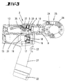
- Fig. 3 is an electromotive hand-held pressing device 2, with one as previously described Return valve.
- a pressing device 2 is for example from the unpublished German patent application with the file number 197 31 054 (DE 197 43 747 A1) known.
- An electric motor 15 is arranged in this pressing device 2, which has a reduction gear 16.
- the latter acts on an eccentric via a shaft 17 18, which in turn has a roller bearing 19 on one High-pressure delivery piston 20 acts.
- the electric motor 15 is driven by a Battery or one, integrated in a handle 21 Accumulator 22.
- the hydraulic piston 9 is moved back via the return spring 10 as soon as - as described above - the return valve 1 due to exceeding the predetermined maximum pressure opens.
- valve piston is 3 of the return valve 1 on the back, i.e. from his Piston surface 5 facing away, pot-shaped.
- the inside of the pot protrudes axially aligned with the valve piston 3 Pull part 27 a, with a driving head 28, which by a circumferential flange on the cylindrical Train part 27 is formed.
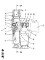
- the sealing seat can also be used in the simplest way Exchange way if necessary.
- Valve piston 3 and seat disk 29 are in a transverse bore 30 of the pump cylinder 31 arranged and through this centered.
- a snap ring 33 rear of the driving head 28 arranged to the valve piston 3 positively on the Holding the tension member 27 is inside the pot wall 32 .
- the pressure spring 8 acts via the tension member 27 in the area of a centrally on the driving head 28 arranged, diameter-reduced pin 40 the valve piston 3 in the direction of the seat disk 29 on.
- the pressure spring 8 is supported on a floor 34 of a likewise pot-like, screwed into the bore 30 Screw body 35 from.
- the latter is penetrated in the axial direction by the Traction part 27, at its free, from the pump cylinder 31st protruding end of a lever arm 36 of an operating rocker 37 is articulated.
- the latter is based approximately in the middle in the longitudinal direction over a cross section circular segment-shaped cams 38 on the From the outer surface of the pump cylinder 31 and forms on it free end of an actuation button that is led outwards 39 out.
- valve piston 3 sits in this initial locking position axial distance to the screw body 35 in order to be exceeded of the maximum pressure an axial displacement of the To ensure valve piston 3.
- adjusting gap is also to the oil reservoir 13 open relief bore 14 positioned.
- valve piston 3 After falling below the piston surface 5 and defined by the force of the pressure spring 8 limiting pressure the valve piston 3 falls in automatically its initial lock position back.
- the screw body 35 also serves to adjust the desired bias of the pressure spring and thus to Adjustment of the limit pressure.
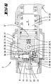
- FIG. 7 is an alternative embodiment of the Return valve 1 shown. Contrary to the previously described The exemplary embodiment is the valve piston 3 of the return valve 1 not pot-like, but hollow cylindrical with essentially constant strength the pot wall 32 is formed.
- the valve piston thus formed 3 is penetrated by the axially aligned to this Switzerlandteil 27, its plate-like driving head 28 is caught by one, a driving nose forming radial collar 40 of the valve piston 3.
- the latter protrudes from the pot wall 32 into the interior of the valve piston 3, the radial extension of this collar 40 is dimensioned such that this is also a centering of the tension member 27 causes.
- the pressure spring 8 comprising the tension part 27 supports one end on the floor 34 of the screw body 35 and otherwise rearward of the radial collar 40 of the valve piston 3, to act on the valve piston 3 and also over the radial collar 40 of the tension member 27 in the valve closure position.
- the distance b between the annular groove 42 and the piston surface 5 is 5 dimensioned larger than the diameter c of the drain opening 12. It follows that in the locked state of the return valve 1 a closed scope of the valve piston 3, the drain opening 12 relative to the formed between piston surface 5 and seat disc 29 Gap closes.
- the annular groove 42 stands over an axially directed passage opening 44 in connection with the valve piston surface 5.
- the diameter of this passage opening 44 is kept low. In the embodiment shown corresponds to the flow opening diameter about half the diameter of the oil inlet bore 7.
- the passage opening 44 mentioned serves in the stationary, closed operation, inevitable residual oil quantities in the annular groove 42 to drain what residual amounts over the gap 42 formed through the drain opening 12 can run without this an increase in pressure in the remaining gap between Piston surface 5 and seat disc 29 results.
- the flow opening 44 is however kept so small that at one Opening the return valve 1 of the valve piston 3 without any problems is shifted to the open position because the here in the space between piston surface 5 and Seat disc 29 entering oil due to the amount also leads to a closure of the passage opening 44.
- the passage opening 44 therefore has no effect disadvantageous on the opening properties of the valve out.
- valve piston 3 After falling below the piston surface 5 and the partial piston surface 41 of the driving head 28 and through the force of the pressure spring 8 defined limiting pressure the valve piston 3 falls automatically into its Exit closure position back, with residual quantities between Piston surface 5 and seat disc 29 through the passage opening 44 are passed into the annular groove 42, resulting in a faster pressure reduction and thus a faster Closing the valve leads.
- the in the annular groove 42nd The residual oil quantity collected can be closed in accordance with Fig. 7 through the gap 43 through the drain opening 12 in drain the oil reservoir 13.
- annular groove 42 in the cylinder bore 30 of the pump cylinder 31 provided at the level of the drain opening 12, wherein the ring groove height corresponds to the drain opening diameter.
- the passage opening 44 opens in this embodiment in a radial bore 45 of the valve piston 3. This is spaced from the piston surface 5 by a dimension b, which dimension b is chosen larger than the diameter c of the drain opening 12.
- the radial bore 45 is therefore largely covered radially through the bore wall of the pump cylinder 31 under Leaving a gap 43 to the annular groove 42, over which Gap 43 residual oil can run off.
- This radial bore 45 is also preferably opposite arranged to the drain opening 12.
- Fig. 8 1 The operation of the return valve shown in Fig. 8 1 corresponds to that described with reference to FIG. 7 Embodiment, being in both embodiments also a manual displacement of the valve piston 3 take place via the tension member 37 in the open position can.
- one with an arm 36 is on the end the tension member 27 acting via a pump cylinder side mounted pivot 46 or the like pivotable Actuator rocker 37 provided.
- used return valve 1 can also in hand or foot operated press tools use Find.
Landscapes
- Engineering & Computer Science (AREA)
- Mechanical Engineering (AREA)
- Manufacturing & Machinery (AREA)
- Safety Valves (AREA)
- Press Drives And Press Lines (AREA)
- Electrical Discharge Machining, Electrochemical Machining, And Combined Machining (AREA)
- Fluid-Pressure Circuits (AREA)
- Actuator (AREA)
- Braking Arrangements (AREA)
- Hand Tools For Fitting Together And Separating, Or Other Hand Tools (AREA)
- Encapsulation Of And Coatings For Semiconductor Or Solid State Devices (AREA)
- Manufacturing Of Electrical Connectors (AREA)
- Braking Systems And Boosters (AREA)
Priority Applications (2)
| Application Number | Priority Date | Filing Date | Title |
|---|---|---|---|
| EP02000014A EP1244187A1 (de) | 1997-10-15 | 1998-10-15 | Hydraulisches Pressgerät und Verfahren zum Betreiben desselben |
| DE29824642U DE29824642U1 (de) | 1997-10-15 | 1998-10-15 | Hydraulisches Preßgerät |
Applications Claiming Priority (5)
| Application Number | Priority Date | Filing Date | Title |
|---|---|---|---|
| DE19745483 | 1997-10-15 | ||
| DE19745483 | 1997-10-15 | ||
| DE19825160A DE19825160A1 (de) | 1997-10-15 | 1998-06-05 | Hydraulisches Preßgerät und Verfahren zum Betreiben desselben |
| DE19825160 | 1998-06-05 | ||
| PCT/EP1998/006532 WO1999019947A1 (de) | 1997-10-15 | 1998-10-15 | Hydraulisches pressgerät und verfahren zum betreiben desselben |
Related Child Applications (1)
| Application Number | Title | Priority Date | Filing Date |
|---|---|---|---|
| EP02000014A Division EP1244187A1 (de) | 1997-10-15 | 1998-10-15 | Hydraulisches Pressgerät und Verfahren zum Betreiben desselben |
Publications (2)
| Publication Number | Publication Date |
|---|---|
| EP0944937A1 EP0944937A1 (de) | 1999-09-29 |
| EP0944937B1 true EP0944937B1 (de) | 2002-03-27 |
Family
ID=26040833
Family Applications (1)
| Application Number | Title | Priority Date | Filing Date |
|---|---|---|---|
| EP98951524A Expired - Lifetime EP0944937B1 (de) | 1997-10-15 | 1998-10-15 | Hydraulisches pressgerät |
Country Status (9)
| Country | Link |
|---|---|
| US (2) | US6276186B1 (da) |
| EP (1) | EP0944937B1 (da) |
| JP (1) | JP2002510380A (da) |
| AT (1) | ATE215273T1 (da) |
| AU (1) | AU9750498A (da) |
| DK (1) | DK0944937T3 (da) |
| ES (1) | ES2172224T3 (da) |
| PT (1) | PT944937E (da) |
| WO (1) | WO1999019947A1 (da) |
Cited By (11)
| Publication number | Priority date | Publication date | Assignee | Title |
|---|---|---|---|---|
| DE202006001889U1 (de) * | 2006-02-03 | 2007-03-08 | Novopress Gmbh Pressen Und Presswerkzeuge & Co. Kg | Antriebseinheit für ein Preßgerät |
| DE202007017421U1 (de) | 2007-07-13 | 2008-11-20 | Gustav Klauke Gmbh | Hand-Signiergerät zum Signieren von Werkstücken |
| EP2070660A2 (de) | 2007-12-14 | 2009-06-17 | Gustav Klauke GmbH | Hydraulisches Pressgerät |
| DE102008023719A1 (de) | 2007-12-14 | 2009-06-18 | Gustav Klauke Gmbh | Hydraulisches Pressgerät |
| DE102009026273A1 (de) | 2009-07-02 | 2011-01-05 | Gustav Klauke Gmbh | Hydraulisches Pressgerät |
| DE102007005837B4 (de) * | 2006-02-03 | 2016-04-07 | Novopress Gmbh Pressen Und Presswerkzeuge & Co. Kg | Antriebseinheit für ein Preßgerät |
| DE102015102806A1 (de) | 2015-02-27 | 2016-09-01 | Gustav Klauke Gmbh | Verfahren zum Betreiben eines hydraulisch betriebenen Handgerätes sowie hydraulisch betriebenes Handgerät |
| WO2018001691A1 (de) | 2016-06-29 | 2018-01-04 | Gustav Klauke Gmbh | Verfahren zum betreiben eines hydraulisch betriebenen handgerätes sowie hydraulisch betriebenes handgerät |
| DE102017112481A1 (de) | 2016-10-07 | 2018-04-12 | Gustav Klauke Gmbh | Verfahren zum Betreiben eines motorisch betätigten Hand-Verpressgerätes |
| WO2022029320A2 (de) | 2020-08-06 | 2022-02-10 | Gustav Klauke Gmbh | Pressbacken sowie verfahren zur herstellung eines presslings und verfahren zum verpressen mit pressbacken |
| EP4338892A1 (en) * | 2022-06-17 | 2024-03-20 | Milwaukee Electric Tool Corporation | Power tool hydraulic system |
Families Citing this family (80)
| Publication number | Priority date | Publication date | Assignee | Title |
|---|---|---|---|---|
| GB9923266D0 (en) * | 1999-10-02 | 1999-12-08 | Textron Fastening Syst Ltd | Riveting apparatus |
| USD468604S1 (en) | 2001-02-12 | 2003-01-14 | Rothenberger Werkzeuge Aktiengesellschaft | Hand tool for compressing pipes or pipe connectors |
| US6446482B1 (en) * | 2001-09-17 | 2002-09-10 | Fci Americas Technology, Inc. | Battery operated hydraulic compression tool with rapid ram advance |
| DE20120204U1 (de) * | 2001-12-13 | 2003-04-17 | Gustav Klauke GmbH, 42855 Remscheid | Hydraulisches Verpressgerät |
| US6745611B2 (en) * | 2002-02-19 | 2004-06-08 | Fci Americas Technology, Inc. | Battery powered hydraulic tool |
| US6668613B2 (en) * | 2002-04-09 | 2003-12-30 | Fci Americas Technology, Inc. | Hydraulic compression tool and hydraulic compression tool motor |
| US6666064B2 (en) * | 2002-04-19 | 2003-12-23 | Fci Americas Technology, Inc. | Portable hydraulic crimping tool |
| US6792789B1 (en) | 2003-04-03 | 2004-09-21 | Fci Americas Technology, Inc. | Hydraulic tool having removable cutting dies and crimping dies |
| DE10329007A1 (de) * | 2003-06-27 | 2005-01-13 | Gustav Klauke Gmbh | Verriegelungsbolzen zur Befestigung eines Werkzeuges an einem hydraulischen Verpressgerät |
| WO2005053909A1 (de) * | 2003-12-04 | 2005-06-16 | Von Arx Ag | Elektrisch betriebenes presswerkzeuggerät |
| US20080016939A1 (en) * | 2004-07-02 | 2008-01-24 | Egbert Frenken | Pair of pressing jaws for hydraulic or electric pressing tools |
| US7216523B2 (en) | 2004-07-02 | 2007-05-15 | Gustav Klauke Gmbh | Pair of pressing jaws for hydraulic or electric pressing tools, and insulating covering for a pressing jaw |
| DE202006013693U1 (de) * | 2006-09-07 | 2008-01-17 | Gustav Klauke Gmbh | Pressbackenpaar für hydraulische oder elektrische Verpressgeräte |
| EP1724043A1 (en) * | 2005-05-18 | 2006-11-22 | Gerd Friedrich Guenter Dr. Koennecker | Hydraulic shears or similar tools with a piston driven by a linear electric motor |
| US7340936B2 (en) * | 2005-06-13 | 2008-03-11 | Shear Tech, Inc. | Handheld crimping tool and method of using same |
| DE102006003044B4 (de) | 2006-01-23 | 2015-10-08 | Gustav Klauke Gmbh | Hydraulisch angetriebenes Verpressgerät sowie Verfahren zum Verpressen eines Fittings |
| US7533556B2 (en) * | 2006-03-15 | 2009-05-19 | Fci Americas Technology, Inc. | Hydraulic tool release system |
| US8276430B2 (en) * | 2006-09-11 | 2012-10-02 | Cembre S.P.A. | Hydraulic pressing and/or cutting tool and mechanism for converting a rotary motion into a translational oscillating motion for this tool |
| US7841223B2 (en) * | 2006-10-12 | 2010-11-30 | Burndy Technology Llc | Rocker switch |
| EP3243604B1 (de) | 2007-05-16 | 2019-11-27 | Gustav Klauke GmbH | Motorisch betriebenes hand-verpressgerät und verfahren zum betreiben eines motorisch betätigten hand-verpressgerätes |
| US7979980B2 (en) * | 2007-07-11 | 2011-07-19 | Emerson Electric Co. | Tool for powered pressing of cable connectors |
| US8595928B2 (en) | 2007-09-10 | 2013-12-03 | John Mezzalingua Associates, LLC | Method for installing a coaxial cable connector onto a cable |
| US10819077B2 (en) | 2007-09-10 | 2020-10-27 | John Mezzalingua Associates, LLC | Compression tool with biasing member |
| US8661656B2 (en) * | 2007-09-10 | 2014-03-04 | John Mezzallingua Associates, LLC | Hydraulic compression tool for installing a coaxial cable connector and method of operating thereof |
| US8516696B2 (en) * | 2007-09-10 | 2013-08-27 | John Mezzalingua Associates, LLC | Hydraulic compression tool for installing a coaxial cable connector and method of operating thereof |
| US7908741B2 (en) * | 2007-09-10 | 2011-03-22 | John Mezzalingua Associates, Inc. | Hydraulic compression tool for installing a coaxial cable connector |
| US7921549B2 (en) * | 2007-09-10 | 2011-04-12 | John Mezzalingua Associates, Inc. | Tool and method for connecting a connector to a coaxial cable |
| KR20090129835A (ko) * | 2008-06-13 | 2009-12-17 | (주)래디안트 | 단말기의 위치를 추정하는 장치 및 시스템 |
| DE202008015574U1 (de) * | 2008-11-24 | 2009-12-31 | Novopress Gmbh Pressen Und Presswerkzeuge & Co. Kg | Antriebseinrichtung für ein Pressgerät sowie Pressgerät mit einer solchen Antriebseinrichtung |
| US9209585B2 (en) * | 2010-02-18 | 2015-12-08 | Tyco Electronics Corporation | Crimping tool head |
| DE102010000545A1 (de) * | 2010-02-25 | 2011-08-25 | Joiner's Bench GmbH, 42859 | Hydraulische Pressvorrichtung |
| DE102010049946B4 (de) * | 2010-10-28 | 2013-04-18 | Novopress Gmbh Pressen Und Presswerkzeuge & Co. Kg | Hydraulik-Presswerkzeug sowie Verfahren zum Steuern eines Hydraulik-Presswerkzeugs |
| WO2012142188A2 (en) | 2011-04-11 | 2012-10-18 | Milwaukee Electric Tool Corporation | Hydraulic hand-held knockout punch driver |
| DE102011052350A1 (de) | 2011-08-02 | 2013-02-07 | Gustav Klauke Gmbh | Backenpaar zum Ausstanzen von Löchern |
| DE202011109251U1 (de) * | 2011-12-17 | 2013-03-18 | Novopress Gmbh Pressen Und Presswerkzeuge & Co. Kg | Elektrohydraulisches Pressgerät |
| DE102012104538A1 (de) | 2012-05-25 | 2013-11-28 | Gustav Klauke Gmbh | Werkzeug |
| CN204573232U (zh) | 2012-07-31 | 2015-08-19 | 米沃奇电动工具公司 | 多功能阀 |
| DE102012109255A1 (de) | 2012-09-28 | 2014-04-03 | Gustav Klauke Gmbh | Handarbeitsgerät, Hand-Aufweitgerät, hydraulische Kolben-/Zylinderanordnung und Verfahren zum Betreiben eines Handarbeitsgerätes |
| WO2014063183A1 (en) * | 2012-10-26 | 2014-05-01 | Legend Corporate Services Pty Ltd | Hydraulically actuated tool |
| DE102013100183A1 (de) | 2013-01-09 | 2014-07-10 | Gustav Klauke Gmbh | Hydraulisch betätigbare Pressvorrichtung, Verfahren zur Durchführung einer Verpressung, Verfahren zur Herstellung einer elektrisch leitfähigen Pressverbindung, elektrisch leitfähig verpresste Presshülse, Verfahren zum Klemmen eines Werkstücks und hydraulische Vorrichtung |
| DE102013101978A1 (de) | 2013-02-28 | 2014-08-28 | Gustav Klauke Gmbh | Hydraulisches Presswerkzeug |
| US9388885B2 (en) | 2013-03-15 | 2016-07-12 | Ideal Industries, Inc. | Multi-tool transmission and attachments for rotary tool |
| DE102013107294A1 (de) | 2013-07-10 | 2015-01-15 | Gustav Klauke Gmbh | Handarbeitsgerät und Hand-Aufweitgerät |
| EP2835540B1 (de) | 2013-08-08 | 2016-04-27 | HAWE Hydraulik SE | Hydraulikantrieb |
| US10226826B2 (en) | 2013-10-22 | 2019-03-12 | Milwaukee Electric Tool Corporation | Hydraulic power tool |
| US20150305318A1 (en) | 2014-04-23 | 2015-10-29 | William R. Moriarty | Furniture Protector against Crawling Arthropods |
| DE102014116562A1 (de) | 2014-11-12 | 2016-05-12 | Gustav Klauke Gmbh | Motorbetriebenes Handwerkzeug, Verfahren zur Benutzung eines Handwerkzeuges, Kombination aus einem motorbetriebenen Handwerkzeug und Handschuh |
| CN205977914U (zh) | 2015-05-06 | 2017-02-22 | 米沃奇电动工具公司 | 液压动力工具 |
| US10312653B2 (en) | 2015-05-06 | 2019-06-04 | Milwaukee Electric Tool Corporation | Hydraulic tool |
| CA3113452C (en) | 2015-08-07 | 2022-10-11 | Hubbell Incorporated | Portable hand tool and kit |
| US10471618B2 (en) | 2015-12-08 | 2019-11-12 | Milwaukee Electric Tool Corporation | Control of a cutting tool |
| US10507590B2 (en) | 2016-03-14 | 2019-12-17 | Milwaukee Electric Tool Corporation | Control of a cutting tool |
| ITUA20161807A1 (it) * | 2016-03-18 | 2017-09-18 | Cembre Spa | Utensile oleodinamico di compressione o taglio |
| US10093012B2 (en) | 2016-09-23 | 2018-10-09 | Milwaukee Electric Tool Corporation | Hydraulic power tool |
| DE102016219220B4 (de) * | 2016-10-04 | 2020-10-01 | Hawe Hydraulik Se | Hydraulikantrieb |
| US10981264B2 (en) | 2016-10-07 | 2021-04-20 | Milwaukee Electric Tool Corporation | Hydraulic power tool |
| CN106944959B (zh) * | 2017-03-10 | 2024-02-02 | 台州瑞祺工具股份有限公司 | 一种自动回油式液压压管钳 |
| DE102017219258B3 (de) * | 2017-10-26 | 2019-03-28 | Hawe Hydraulik Se | Hydraulikkomponente, Werkzeugkolben mit einer Hydraulikkomponente und Presswerkzeug mit einem Werkzeugkolben |
| DE102018122021A1 (de) | 2018-09-10 | 2020-03-12 | Gustav Klauke Gmbh & Co | Handwerkzeug und Hüllteil für ein Handwerkzeug |
| DE102018121971A1 (de) | 2018-09-10 | 2020-03-12 | Gustav Klauke Gmbh | Presswerkzeug |
| EP3650175A1 (de) * | 2018-11-06 | 2020-05-13 | Von Arx AG | Hydraulische pumpen-ventilvorrichtung für eine pressmaschine |
| EP3650176B1 (de) * | 2018-11-07 | 2025-12-24 | Emerson Professional Tools AG | Pressmaschine |
| DE102019217816B4 (de) | 2018-11-29 | 2025-11-13 | Ridge Tool Company | Werkzeugköpfe für scherarbeiten |
| US11999042B2 (en) | 2019-08-29 | 2024-06-04 | Milwaukee Electric Tool Corporation | Hydraulic tool having ram piston with integrated overload assembly |
| US12202117B2 (en) | 2019-09-03 | 2025-01-21 | Milwaukee Electric Tool Corporation | Tool with hydraulic system for regenerative extension and two-speed operation |
| TWI717112B (zh) * | 2019-11-19 | 2021-01-21 | 科頡工業股份有限公司 | 活塞泵及具有該活塞泵的夾持裝置 |
| US12040581B2 (en) | 2020-06-26 | 2024-07-16 | Ilsco, Llc | Crimping assembly, tool and die design |
| TWI755892B (zh) | 2020-10-15 | 2022-02-21 | 科頡工業股份有限公司 | 電纜端子之壓接裝置 |
| CN214443619U (zh) | 2020-11-27 | 2021-10-22 | 米沃奇电动工具公司 | 电动螺纹杆切割机 |
| DE102021107120A1 (de) | 2020-12-03 | 2022-06-09 | Gustav Klauke Gmbh | Hydraulikzylinder, hydraulisches Arbeitswerkzeug mit einem Arbeitskopf und einem Hydraulikzylinder und Verfahren zur Stoßdämpfung eines in einem Hydraulikzylinder bewegbaren Arbeitskolbens |
| EP4255680A1 (de) | 2020-12-03 | 2023-10-11 | Gustav Klauke GmbH | Hydraulisches arbeitswerkzeug mit einrichtung zur stossdämpfung |
| USD1042068S1 (en) * | 2021-05-19 | 2024-09-17 | Gustav Klauke Gmbh | Hydraulic press tool |
| US12224545B2 (en) | 2021-06-21 | 2025-02-11 | Milwaukee Electric Tool Corporation | Systems and methods for evaluating crimp applications |
| CN113649483B (zh) * | 2021-07-26 | 2024-04-26 | 浙江飞越机电有限公司 | 多功能电动液压管件加工工具 |
| USD1012142S1 (en) | 2022-01-28 | 2024-01-23 | Milwaukee Electric Tool Corporation | Strut shearing die |
| USD1016111S1 (en) | 2022-01-28 | 2024-02-27 | Milwaukee Electric Tool Corporation | Strut shearing die |
| TWI820886B (zh) * | 2022-08-31 | 2023-11-01 | 科頡工業股份有限公司 | 活塞泵自動回油結構 |
| TWI864925B (zh) * | 2023-08-01 | 2024-12-01 | 科頡工業股份有限公司 | 自動回油結構 |
| NO348628B1 (en) * | 2023-08-22 | 2025-04-07 | Gmv As | Roll grooving tool |
| TWI873054B (zh) * | 2024-06-27 | 2025-02-11 | 科頡工業股份有限公司 | 液壓手工具 |
Family Cites Families (32)
| Publication number | Priority date | Publication date | Assignee | Title |
|---|---|---|---|---|
| US2254613A (en) * | 1938-08-13 | 1941-09-02 | Matthysse Irving Frederick | Hydraulic press |
| US2869407A (en) * | 1954-10-15 | 1959-01-20 | Greenlee Bros & Co | Portable metal working tool |
| BE545539A (da) | 1955-02-24 | |||
| BE547959A (da) | 1955-05-20 | |||
| US3087530A (en) | 1961-01-10 | 1963-04-30 | Burndy Corp | Single pole hot stick |
| JPS457687Y1 (da) * | 1966-05-13 | 1970-04-14 | ||
| DE7413845U (de) | 1974-04-20 | 1977-02-24 | Adolf Diener Apparate- U. Maschinenbau, 7921 Hermaringen | Pneumatisch-hydraulisches blindnietgeraet |
| JPS518604A (ja) * | 1974-07-11 | 1976-01-23 | Daikin Ind Ltd | Kanketsukyuyuhonpusochi |
| JPS5439713Y2 (da) * | 1974-07-11 | 1979-11-24 | ||
| DE7428678U (de) | 1974-08-24 | 1975-02-13 | Kraenzle J | Druckschaltventil |
| US4132107A (en) * | 1977-06-24 | 1979-01-02 | Izumi Products Company | Hydraulic compression tool |
| JPS628144Y2 (da) * | 1977-08-22 | 1987-02-25 | ||
| DE3033723A1 (de) | 1980-09-08 | 1981-03-26 | Nowikontakt AB, Tragsund | Hydraulisch betriebenes klemmwerkzeug |
| IT1149409B (it) | 1982-01-07 | 1986-12-03 | Cembre Srl | Martinetto idraulica manuale per la compressione di connettori elettrici su cavi elettrici e conduttori in genere |
| JPS5924056U (ja) * | 1982-08-06 | 1984-02-15 | ヤマト消火器株式会社 | 消火設備用選択弁 |
| JPS5968869U (ja) * | 1982-11-01 | 1984-05-10 | 富士精工株式会社 | 環状メタルシ−ル部を有するバルブ |
| JPS6080877U (ja) * | 1983-11-09 | 1985-06-05 | 産機興業株式会社 | 自動復帰形手動油圧式工具 |
| US4796461A (en) | 1986-06-02 | 1989-01-10 | Greenlee Textron Inc. | Hydraulic crimping tool |
| JPH0524459Y2 (da) * | 1987-02-13 | 1993-06-22 | ||
| DE3719442A1 (de) | 1987-06-11 | 1988-12-22 | Pfisterer Elektrotech Karl | Tragbare presse zur herstellung von pressverbindungen |
| DE3835696C2 (de) | 1988-10-20 | 1993-12-23 | Pfisterer Elektrotech Karl | Tragbare Presse zur Herstellung von Preßverbindungen |
| CH676568A5 (da) | 1988-11-18 | 1991-02-15 | Nussbaum & Co Ag R | |
| US5195354A (en) | 1989-03-31 | 1993-03-23 | Japan Storage Battery Co., Ltd. | Cam crank mechanism and motor driven hydraulic tool |
| EP0389716B1 (en) * | 1989-03-31 | 1994-05-18 | Japan Storage Battery Company Limited | Cam crank mechanism and motor driven hydraulic tool |
| US4942757A (en) * | 1989-03-31 | 1990-07-24 | Burndy Corporation | Hydraulic press with infinite head rotation |
| DE4206439A1 (de) | 1992-02-29 | 1993-09-02 | Tectonic Gmbh | Presswerkzeug zum aufpressen eines zylindrischen pressteils oder eines einen zylindrischen abschnitt aufweisenden pressteils auf ein rundprofil, insbesondere eine rohrleitung |
| FR2708674B1 (fr) * | 1993-07-30 | 1996-05-15 | Dubuis | Pompe volumétrique à piston animé d'un mouvement linéaire alternatif. |
| DE29509976U1 (de) | 1995-05-27 | 1995-08-24 | Kretzschmar, Michael, Dr., 22453 Hamburg | Druckmittelzange |
| DE19535691C1 (de) | 1995-09-26 | 1997-01-23 | Rothenberger Werkzeuge Masch | Hydraulisch angetriebenes Handwerkzeug |
| JPH09242886A (ja) * | 1996-03-06 | 1997-09-16 | Kameya:Kk | 止水弁漏洩防止装置 |
| US5979215A (en) * | 1998-10-14 | 1999-11-09 | Framatome Connectors Usa Inc. | Hydraulic tool with rapid ram advance |
| EP1182292A1 (en) * | 2000-08-16 | 2002-02-27 | The Procter & Gamble Company | Apparatus for cleaning and refreshing fabrics with an improved ultrasonic nebulizer, and improved ultrasonic nebulizer |
-
1998
- 1998-10-15 JP JP52104599A patent/JP2002510380A/ja active Pending
- 1998-10-15 AU AU97504/98A patent/AU9750498A/en not_active Abandoned
- 1998-10-15 AT AT98951524T patent/ATE215273T1/de not_active IP Right Cessation
- 1998-10-15 WO PCT/EP1998/006532 patent/WO1999019947A1/de not_active Ceased
- 1998-10-15 US US09/319,908 patent/US6276186B1/en not_active Expired - Lifetime
- 1998-10-15 ES ES98951524T patent/ES2172224T3/es not_active Expired - Lifetime
- 1998-10-15 DK DK98951524T patent/DK0944937T3/da active
- 1998-10-15 PT PT98951524T patent/PT944937E/pt unknown
- 1998-10-15 EP EP98951524A patent/EP0944937B1/de not_active Expired - Lifetime
-
2001
- 2001-06-06 US US09/876,288 patent/US6401515B2/en not_active Expired - Lifetime
Cited By (14)
| Publication number | Priority date | Publication date | Assignee | Title |
|---|---|---|---|---|
| DE202006001889U1 (de) * | 2006-02-03 | 2007-03-08 | Novopress Gmbh Pressen Und Presswerkzeuge & Co. Kg | Antriebseinheit für ein Preßgerät |
| DE102007005837B4 (de) * | 2006-02-03 | 2016-04-07 | Novopress Gmbh Pressen Und Presswerkzeuge & Co. Kg | Antriebseinheit für ein Preßgerät |
| DE202007017421U1 (de) | 2007-07-13 | 2008-11-20 | Gustav Klauke Gmbh | Hand-Signiergerät zum Signieren von Werkstücken |
| EP2070660A2 (de) | 2007-12-14 | 2009-06-17 | Gustav Klauke GmbH | Hydraulisches Pressgerät |
| DE102008023719A1 (de) | 2007-12-14 | 2009-06-18 | Gustav Klauke Gmbh | Hydraulisches Pressgerät |
| DE102009026273A1 (de) | 2009-07-02 | 2011-01-05 | Gustav Klauke Gmbh | Hydraulisches Pressgerät |
| DE102015102806A1 (de) | 2015-02-27 | 2016-09-01 | Gustav Klauke Gmbh | Verfahren zum Betreiben eines hydraulisch betriebenen Handgerätes sowie hydraulisch betriebenes Handgerät |
| US10688646B2 (en) | 2015-02-27 | 2020-06-23 | Gustav Klauke Gmbh | Method for operating a hydraulically operated hand-held device and hydraulically operated hand-held device |
| DE102015102806B4 (de) * | 2015-02-27 | 2025-08-07 | Gustav Klauke Gmbh | Hydraulisch betriebenes Handgerät |
| WO2018001691A1 (de) | 2016-06-29 | 2018-01-04 | Gustav Klauke Gmbh | Verfahren zum betreiben eines hydraulisch betriebenen handgerätes sowie hydraulisch betriebenes handgerät |
| DE102016111874A1 (de) | 2016-06-29 | 2018-01-04 | Gustav Klauke Gmbh | Verfahren zum Betreiben eines hydraulisch betriebenen Handgerätes sowie hydraulisch betriebenes Handgerät |
| DE102017112481A1 (de) | 2016-10-07 | 2018-04-12 | Gustav Klauke Gmbh | Verfahren zum Betreiben eines motorisch betätigten Hand-Verpressgerätes |
| WO2022029320A2 (de) | 2020-08-06 | 2022-02-10 | Gustav Klauke Gmbh | Pressbacken sowie verfahren zur herstellung eines presslings und verfahren zum verpressen mit pressbacken |
| EP4338892A1 (en) * | 2022-06-17 | 2024-03-20 | Milwaukee Electric Tool Corporation | Power tool hydraulic system |
Also Published As
| Publication number | Publication date |
|---|---|
| US20010027676A1 (en) | 2001-10-11 |
| US6276186B1 (en) | 2001-08-21 |
| US6401515B2 (en) | 2002-06-11 |
| WO1999019947A1 (de) | 1999-04-22 |
| EP0944937A1 (de) | 1999-09-29 |
| PT944937E (pt) | 2002-07-31 |
| ATE215273T1 (de) | 2002-04-15 |
| DK0944937T3 (da) | 2002-07-22 |
| JP2002510380A (ja) | 2002-04-02 |
| ES2172224T3 (es) | 2002-09-16 |
| AU9750498A (en) | 1999-05-03 |
Similar Documents
| Publication | Publication Date | Title |
|---|---|---|
| EP0944937B1 (de) | Hydraulisches pressgerät | |
| EP1244187A1 (de) | Hydraulisches Pressgerät und Verfahren zum Betreiben desselben | |
| EP2024112B1 (de) | Verfahren zum betreiben eines hydraulischen verpressgerätes sowie hydraulisches verpressgerät | |
| DE3504650C2 (de) | Bohrhammer mit Verstärkung der Betätigungskraft für die Kupplung des Schlagantriebes | |
| DE4215972C2 (de) | Hydraulische Betätigungseinrichtung | |
| DE69622001T2 (de) | Vorrichtung zum Setzen und Eindrehen von Schrauben | |
| DE2902290C2 (de) | Rückschlagventileinrichtung in einer druckmittelbetätigten Reibscheibenkupplung | |
| EP0386330B1 (de) | Kupplungsbetätigungsvorrichtung | |
| DE3006468C2 (da) | ||
| DE4116842A1 (de) | Einrichtung zur hubbegrenzung eines hydraulikzylinders | |
| DE4112570C2 (de) | Auslöseventilmechanismus in einer flüssigkeitsbetriebenen LINEAR-Antriebsvorrichtung für eine tragbare Schneidvorrichtung oder dgl. | |
| EP2771134B1 (de) | Hochdruckreinigungsgerät | |
| DE19956703B4 (de) | Hydraulisches Lochstanzwerkzeug | |
| DE2502944B2 (de) | Vorrichtung zum Aus- und Einschalten des Spiels bei einer Anhängerkupplung | |
| DE69800825T2 (de) | Rohrschmiedegerät mit hydraulischem Antrieb | |
| DE3237324C2 (da) | ||
| DE2751607C2 (de) | Schnellösevorrichtung für Federspeicherbremszylinder, insbesondere für Kraftfahrzeugbremsen | |
| DE952575C (de) | Verriegelungsvorrichtung fuer zwei durch ein Druckmittel relativ zueinander bewegbare Glieder | |
| DE2419190C3 (de) | Pneumatisch-hydraulisches Blindnietgerät | |
| DE2919068C2 (de) | Rasenmäher mit Antrieb durch einen Brennkraftmotor | |
| AT3500U1 (de) | Holzspaltmaschine | |
| DE19815889A1 (de) | Inchbremseinrichtung | |
| DE60100002T2 (de) | Automatisches Rohrverpressgerät mit hydraulischem Antrieb | |
| DE102010012158A1 (de) | Vorrichtung zum Verriegeln eines axial verschiebbaren Bauteils einer hydraulischen Anlage | |
| DE1808221C3 (de) | Hydraulische Vorrichtung zum Treiben eines hydraulischen Werkzeuges zwecks Ausführung eines Klemmverfahrens |
Legal Events
| Date | Code | Title | Description |
|---|---|---|---|
| PUAI | Public reference made under article 153(3) epc to a published international application that has entered the european phase |
Free format text: ORIGINAL CODE: 0009012 |
|
| 17P | Request for examination filed |
Effective date: 19990604 |
|
| AK | Designated contracting states |
Kind code of ref document: A1 Designated state(s): AT BE CH CY DE DK ES FI FR GB GR IE IT LI LU MC NL PT SE |
|
| GRAG | Despatch of communication of intention to grant |
Free format text: ORIGINAL CODE: EPIDOS AGRA |
|
| REG | Reference to a national code |
Ref country code: GB Ref legal event code: IF02 |
|
| GRAG | Despatch of communication of intention to grant |
Free format text: ORIGINAL CODE: EPIDOS AGRA |
|
| GRAH | Despatch of communication of intention to grant a patent |
Free format text: ORIGINAL CODE: EPIDOS IGRA |
|
| RTI1 | Title (correction) |
Free format text: HYDRAULIC PRESSING DEVICE |
|
| 17Q | First examination report despatched |
Effective date: 20011217 |
|
| GRAH | Despatch of communication of intention to grant a patent |
Free format text: ORIGINAL CODE: EPIDOS IGRA |
|
| GRAA | (expected) grant |
Free format text: ORIGINAL CODE: 0009210 |
|
| AK | Designated contracting states |
Kind code of ref document: B1 Designated state(s): AT BE CH CY DE DK ES FI FR GB GR IE IT LI LU MC NL PT SE |
|
| REF | Corresponds to: |
Ref document number: 215273 Country of ref document: AT Date of ref document: 20020415 Kind code of ref document: T |
|
| REG | Reference to a national code |
Ref country code: CH Ref legal event code: EP |
|
| REF | Corresponds to: |
Ref document number: 59803508 Country of ref document: DE Date of ref document: 20020502 |
|
| REG | Reference to a national code |
Ref country code: IE Ref legal event code: FG4D Free format text: GERMAN |
|
| REG | Reference to a national code |
Ref country code: CH Ref legal event code: NV Representative=s name: R. A. EGLI & CO. PATENTANWAELTE |
|
| REG | Reference to a national code |
Ref country code: DK Ref legal event code: T3 |
|
| GBT | Gb: translation of ep patent filed (gb section 77(6)(a)/1977) |
Effective date: 20020628 |
|
| ET | Fr: translation filed | ||
| REG | Reference to a national code |
Ref country code: PT Ref legal event code: SC4A Free format text: AVAILABILITY OF NATIONAL TRANSLATION Effective date: 20020509 |
|
| PLBQ | Unpublished change to opponent data |
Free format text: ORIGINAL CODE: EPIDOS OPPO |
|
| PLBI | Opposition filed |
Free format text: ORIGINAL CODE: 0009260 |
|
| PGFP | Annual fee paid to national office [announced via postgrant information from national office to epo] |
Ref country code: FI Payment date: 20020906 Year of fee payment: 5 Ref country code: MC Payment date: 20020906 Year of fee payment: 5 Ref country code: LU Payment date: 20020906 Year of fee payment: 5 |
|
| REG | Reference to a national code |
Ref country code: GR Ref legal event code: EP Ref document number: 20020401849 Country of ref document: GR |
|
| PGFP | Annual fee paid to national office [announced via postgrant information from national office to epo] |
Ref country code: AT Payment date: 20020910 Year of fee payment: 5 |
|
| REG | Reference to a national code |
Ref country code: ES Ref legal event code: FG2A Ref document number: 2172224 Country of ref document: ES Kind code of ref document: T3 |
|
| PGFP | Annual fee paid to national office [announced via postgrant information from national office to epo] |
Ref country code: PT Payment date: 20021003 Year of fee payment: 5 |
|
| 26 | Opposition filed |
Opponent name: ROTHENBERGER WERKZEUGE AG Effective date: 20020822 |
|
| PGFP | Annual fee paid to national office [announced via postgrant information from national office to epo] |
Ref country code: GR Payment date: 20021024 Year of fee payment: 5 |
|
| PGFP | Annual fee paid to national office [announced via postgrant information from national office to epo] |
Ref country code: CY Payment date: 20021031 Year of fee payment: 5 |
|
| NLR1 | Nl: opposition has been filed with the epo |
Opponent name: ROTHENBERGER WERKZEUGE AG |
|
| PLBQ | Unpublished change to opponent data |
Free format text: ORIGINAL CODE: EPIDOS OPPO |
|
| PLBI | Opposition filed |
Free format text: ORIGINAL CODE: 0009260 |
|
| PLBF | Reply of patent proprietor to notice(s) of opposition |
Free format text: ORIGINAL CODE: EPIDOS OBSO |
|
| 26 | Opposition filed |
Opponent name: DUBUIS, SOCIETE ANONYME Effective date: 20021223 Opponent name: ROTHENBERGER WERKZEUGE AG Effective date: 20020822 |
|
| NLR1 | Nl: opposition has been filed with the epo |
Opponent name: DUBUIS, SOCIETE ANONYME Opponent name: ROTHENBERGER WERKZEUGE AG |
|
| PLBF | Reply of patent proprietor to notice(s) of opposition |
Free format text: ORIGINAL CODE: EPIDOS OBSO |
|
| PLBP | Opposition withdrawn |
Free format text: ORIGINAL CODE: 0009264 |
|
| PLBB | Reply of patent proprietor to notice(s) of opposition received |
Free format text: ORIGINAL CODE: EPIDOSNOBS3 |
|
| PG25 | Lapsed in a contracting state [announced via postgrant information from national office to epo] |
Ref country code: LU Free format text: LAPSE BECAUSE OF NON-PAYMENT OF DUE FEES Effective date: 20031015 Ref country code: FI Free format text: LAPSE BECAUSE OF NON-PAYMENT OF DUE FEES Effective date: 20031015 Ref country code: AT Free format text: LAPSE BECAUSE OF NON-PAYMENT OF DUE FEES Effective date: 20031015 |
|
| PG25 | Lapsed in a contracting state [announced via postgrant information from national office to epo] |
Ref country code: MC Free format text: LAPSE BECAUSE OF NON-PAYMENT OF DUE FEES Effective date: 20031031 Ref country code: CY Free format text: LAPSE BECAUSE OF NON-PAYMENT OF DUE FEES Effective date: 20031031 |
|
| PG25 | Lapsed in a contracting state [announced via postgrant information from national office to epo] |
Ref country code: PT Free format text: LAPSE BECAUSE OF NON-PAYMENT OF DUE FEES Effective date: 20040430 |
|
| PG25 | Lapsed in a contracting state [announced via postgrant information from national office to epo] |
Ref country code: GR Free format text: LAPSE BECAUSE OF NON-PAYMENT OF DUE FEES Effective date: 20040504 |
|
| REG | Reference to a national code |
Ref country code: PT Ref legal event code: MM4A Free format text: LAPSE DUE TO NON-PAYMENT OF FEES Effective date: 20040430 |
|
| APBP | Date of receipt of notice of appeal recorded |
Free format text: ORIGINAL CODE: EPIDOSNNOA2O |
|
| APAH | Appeal reference modified |
Free format text: ORIGINAL CODE: EPIDOSCREFNO |
|
| APBQ | Date of receipt of statement of grounds of appeal recorded |
Free format text: ORIGINAL CODE: EPIDOSNNOA3O |
|
| APAH | Appeal reference modified |
Free format text: ORIGINAL CODE: EPIDOSCREFNO |
|
| APBU | Appeal procedure closed |
Free format text: ORIGINAL CODE: EPIDOSNNOA9O |
|
| PLAG | Information modified related to despatch of communication that opposition is rejected |
Free format text: ORIGINAL CODE: EPIDOSCREJ1 |
|
| PLCK | Communication despatched that opposition was rejected |
Free format text: ORIGINAL CODE: EPIDOSNREJ1 |
|
| PLBN | Opposition rejected |
Free format text: ORIGINAL CODE: 0009273 |
|
| STAA | Information on the status of an ep patent application or granted ep patent |
Free format text: STATUS: OPPOSITION REJECTED |
|
| 27O | Opposition rejected |
Effective date: 20070619 |
|
| NLR2 | Nl: decision of opposition |
Effective date: 20070619 |
|
| REG | Reference to a national code |
Ref country code: DE Ref legal event code: R008 Ref document number: 59803508 Country of ref document: DE |
|
| REG | Reference to a national code |
Ref country code: DE Ref legal event code: R039 Ref document number: 59803508 Country of ref document: DE Effective date: 20130207 |
|
| REG | Reference to a national code |
Ref country code: FR Ref legal event code: PLFP Year of fee payment: 18 |
|
| REG | Reference to a national code |
Ref country code: CH Ref legal event code: AEN Free format text: TEILNICHTIGKEIT H2 |
|
| REG | Reference to a national code |
Ref country code: FR Ref legal event code: PLFP Year of fee payment: 19 |
|
| REG | Reference to a national code |
Ref country code: DE Ref legal event code: R043 Ref document number: 59803508 Country of ref document: DE |
|
| REG | Reference to a national code |
Ref country code: FR Ref legal event code: PLFP Year of fee payment: 20 |
|
| PGFP | Annual fee paid to national office [announced via postgrant information from national office to epo] |
Ref country code: IE Payment date: 20170914 Year of fee payment: 20 |
|
| PGFP | Annual fee paid to national office [announced via postgrant information from national office to epo] |
Ref country code: DK Payment date: 20171017 Year of fee payment: 20 Ref country code: FR Payment date: 20171013 Year of fee payment: 20 Ref country code: DE Payment date: 20171016 Year of fee payment: 20 |
|
| PGFP | Annual fee paid to national office [announced via postgrant information from national office to epo] |
Ref country code: BE Payment date: 20171012 Year of fee payment: 20 Ref country code: CH Payment date: 20171018 Year of fee payment: 20 Ref country code: SE Payment date: 20171013 Year of fee payment: 20 Ref country code: IT Payment date: 20171025 Year of fee payment: 20 Ref country code: NL Payment date: 20171013 Year of fee payment: 20 Ref country code: ES Payment date: 20171123 Year of fee payment: 20 Ref country code: GB Payment date: 20171013 Year of fee payment: 20 |
|
| REG | Reference to a national code |
Ref country code: DE Ref legal event code: R206 Ref document number: 59803508 Country of ref document: DE |
|
| REG | Reference to a national code |
Ref country code: DE Ref legal event code: R071 Ref document number: 59803508 Country of ref document: DE |
|
| REG | Reference to a national code |
Ref country code: NL Ref legal event code: MK Effective date: 20181014 |
|
| REG | Reference to a national code |
Ref country code: DK Ref legal event code: EUP Effective date: 20181015 |
|
| REG | Reference to a national code |
Ref country code: CH Ref legal event code: PL |
|
| REG | Reference to a national code |
Ref country code: GB Ref legal event code: PE20 Expiry date: 20181014 |
|
| REG | Reference to a national code |
Ref country code: IE Ref legal event code: MK9A |
|
| REG | Reference to a national code |
Ref country code: SE Ref legal event code: EUG |
|
| REG | Reference to a national code |
Ref country code: BE Ref legal event code: MK Effective date: 20181015 |
|
| PG25 | Lapsed in a contracting state [announced via postgrant information from national office to epo] |
Ref country code: IE Free format text: LAPSE BECAUSE OF EXPIRATION OF PROTECTION Effective date: 20181015 |
|
| PG25 | Lapsed in a contracting state [announced via postgrant information from national office to epo] |
Ref country code: GB Free format text: LAPSE BECAUSE OF EXPIRATION OF PROTECTION Effective date: 20181014 |
|
| REG | Reference to a national code |
Ref country code: ES Ref legal event code: FD2A Effective date: 20200721 |
|
| PG25 | Lapsed in a contracting state [announced via postgrant information from national office to epo] |
Ref country code: ES Free format text: LAPSE BECAUSE OF EXPIRATION OF PROTECTION Effective date: 20181016 |