EP0942610A2 - Système et méthode de réglage de la convergence d'une caméra stéréoscopique - Google Patents
Système et méthode de réglage de la convergence d'une caméra stéréoscopique Download PDFInfo
- Publication number
- EP0942610A2 EP0942610A2 EP99104888A EP99104888A EP0942610A2 EP 0942610 A2 EP0942610 A2 EP 0942610A2 EP 99104888 A EP99104888 A EP 99104888A EP 99104888 A EP99104888 A EP 99104888A EP 0942610 A2 EP0942610 A2 EP 0942610A2
- Authority
- EP
- European Patent Office
- Prior art keywords
- image
- camera
- correction
- picked
- stereo
- Prior art date
- Legal status (The legal status is an assumption and is not a legal conclusion. Google has not performed a legal analysis and makes no representation as to the accuracy of the status listed.)
- Granted
Links
Images


Classifications
-
- H—ELECTRICITY
- H04—ELECTRIC COMMUNICATION TECHNIQUE
- H04N—PICTORIAL COMMUNICATION, e.g. TELEVISION
- H04N13/00—Stereoscopic video systems; Multi-view video systems; Details thereof
- H04N13/20—Image signal generators
- H04N13/204—Image signal generators using stereoscopic image cameras
- H04N13/239—Image signal generators using stereoscopic image cameras using two 2D image sensors having a relative position equal to or related to the interocular distance
-
- H—ELECTRICITY
- H04—ELECTRIC COMMUNICATION TECHNIQUE
- H04N—PICTORIAL COMMUNICATION, e.g. TELEVISION
- H04N13/00—Stereoscopic video systems; Multi-view video systems; Details thereof
- H04N13/10—Processing, recording or transmission of stereoscopic or multi-view image signals
- H04N13/106—Processing image signals
- H04N13/111—Transformation of image signals corresponding to virtual viewpoints, e.g. spatial image interpolation
-
- H—ELECTRICITY
- H04—ELECTRIC COMMUNICATION TECHNIQUE
- H04N—PICTORIAL COMMUNICATION, e.g. TELEVISION
- H04N13/00—Stereoscopic video systems; Multi-view video systems; Details thereof
- H04N13/20—Image signal generators
- H04N13/204—Image signal generators using stereoscopic image cameras
- H04N13/246—Calibration of cameras
-
- H—ELECTRICITY
- H04—ELECTRIC COMMUNICATION TECHNIQUE
- H04N—PICTORIAL COMMUNICATION, e.g. TELEVISION
- H04N13/00—Stereoscopic video systems; Multi-view video systems; Details thereof
- H04N13/20—Image signal generators
- H04N13/296—Synchronisation thereof; Control thereof
-
- H—ELECTRICITY
- H04—ELECTRIC COMMUNICATION TECHNIQUE
- H04N—PICTORIAL COMMUNICATION, e.g. TELEVISION
- H04N13/00—Stereoscopic video systems; Multi-view video systems; Details thereof
- H04N13/10—Processing, recording or transmission of stereoscopic or multi-view image signals
- H04N13/106—Processing image signals
- H04N13/167—Synchronising or controlling image signals
-
- H—ELECTRICITY
- H04—ELECTRIC COMMUNICATION TECHNIQUE
- H04N—PICTORIAL COMMUNICATION, e.g. TELEVISION
- H04N13/00—Stereoscopic video systems; Multi-view video systems; Details thereof
- H04N13/10—Processing, recording or transmission of stereoscopic or multi-view image signals
- H04N13/189—Recording image signals; Reproducing recorded image signals
-
- H—ELECTRICITY
- H04—ELECTRIC COMMUNICATION TECHNIQUE
- H04N—PICTORIAL COMMUNICATION, e.g. TELEVISION
- H04N13/00—Stereoscopic video systems; Multi-view video systems; Details thereof
- H04N13/20—Image signal generators
- H04N13/204—Image signal generators using stereoscopic image cameras
- H04N13/25—Image signal generators using stereoscopic image cameras using two or more image sensors with different characteristics other than in their location or field of view, e.g. having different resolutions or colour pickup characteristics; using image signals from one sensor to control the characteristics of another sensor
-
- H—ELECTRICITY
- H04—ELECTRIC COMMUNICATION TECHNIQUE
- H04N—PICTORIAL COMMUNICATION, e.g. TELEVISION
- H04N13/00—Stereoscopic video systems; Multi-view video systems; Details thereof
- H04N2013/0074—Stereoscopic image analysis
- H04N2013/0081—Depth or disparity estimation from stereoscopic image signals
-
- H—ELECTRICITY
- H04—ELECTRIC COMMUNICATION TECHNIQUE
- H04N—PICTORIAL COMMUNICATION, e.g. TELEVISION
- H04N13/00—Stereoscopic video systems; Multi-view video systems; Details thereof
- H04N2013/0074—Stereoscopic image analysis
- H04N2013/0092—Image segmentation from stereoscopic image signals
Definitions
- the present invention relates generally to a stereo camera system and method for adjusting the deviation of an optical axis of a stereo camera.
- Japanese Patent Laid-Open No. 5-157557 discloses that a holding member for connecting and holding a pair of video cameras has parallelism adjusting means for adjusting the arrangement of pixels of an image sensor of one of the video cameras so as to be parallel to the arrangement of pixels of an image sensor of the other video camera, and an optical axis adjusting member for adjusting the optical axis of one of the video cameras so as to be parallel to the optical axis of the other video camera, so that the correlation between the two cameras is mechanically adjusted and held.
- the stereo camera Even if the stereo camera is fixed once, the deviation of the stereo camera is easily caused with secular change. Conventionally, if such a deviation is caused, the stereo camera must be mechanically readjusted. Therefore, it is not only required to carry out the complicated operation, but it also takes a lot of time to readjust the stereo camera, so that there is a limit to the mechanical adjustment to ensure required accuracy.
- Japanese Patent Application No. 9-117268 which is assigned to the present Assignee and incorporated herein by reference, discloses a technique for electrically adjusting the optical position of a stereo camera without the need of any mechanical adjustments.
- This technique can accurately adjust the optical position of a stereo camera to a level, at which it is difficult to mechanically adjust the optical position of the stereo camera, and easily readjust the deviation due to secular change after the adjustment.
- a stereo camera adjusting system for adjusting an optical axis of a stereo camera having first and second cameras arranged at regular intervals, the system comprising: image adjusting means for geometrically transforming an image, which is picked up by the second camera, by a translation correction and a rotation correction, and for geometrically transforming an image, which is picked up by the first camera, by a rotation correction; and correction operating means for calculating a difference between corresponding positions of the images, which are picked up by the first and second cameras, on the basis of distance data obtained by stereo-processing the pair of images picked up by the first and second cameras, and for setting a transforming value for the image transformation so as to remove the difference.
- the correction operating means may calculate the difference on the basis of two distant regions substantially at the same distance and one near region.
- the correction operating means may define a range including regions corresponding to the regions, in the image picked up by the second camera, on the basis of distance data of the distant regions of the image picked up by the first camera, and search the defined range to derive the distant regions of the image picked up by the second camera.
- the image adjusting means may geometrically transform the image, which is picked up by the second camera, by a horizontal translation correction and a vertical translation correction, and the correction operating means may calculate a transforming value for the image transformation based on the horizontal translation correction for the image picked up by the second camera, on the basis of a deviation between the positions of the regions of the images picked up by the first and second cameras, and distances of the regions.
- the correction operating means may set the transforming value for the image transformation on the basis of a pair of images of a landscape picked up by the first and second cameras.
- a stereo camera adjusting method for adjusting an optical axis of a stereo camera having first and second cameras provided at regular intervals, the method comprising the steps of: calculating a difference between corresponding positions of images picked up by the first and second cameras, on the basis of distance data obtained by stereo-processing the pair of images picked up by the first and second cameras; setting a translation correction value and a rotation correction value for the second camera so as to remove the calculated difference; and geometrically transforming the image picked up by the second camera, by a translation correction and a rotation correction, on the basis of the set translation correction value and the set rotation correction value for the second camera.
- the stereo camera adjusting method may further comprise the steps of: setting a rotation correction value for the first camera so as to remove the calculated difference; and geometrically transforming the image picked up by the first camera, by a rotation correction on the basis of the set rotation correction value for the first camera.
- a difference between corresponding positions of images picked up by first and second cameras is calculated. Then, an image transforming value for a rotation correction in the image picked up by the first camera, and image transforming values for a translation correction and a rotation correction in horizontal and vertical directions in the image picked up by the second camera are set so as to remove the difference. Then, the images picked up by the first and second cameras are geometrically transformed to automatically correct the age-based deviation of the optical axis of the stereo camera.
- the age-based deviation of the optical axis of the stereo camera is automatically adjusted while maintaining the operating state thereof from an early stage, in which it is possible to disregard the influence on ranging accuracy, it is possible to always use the stereo camera in an accurately adjusted state, and it is not required to stop the operation of the stereo camera in a field unlike the technique for picking up an image of a special adjusting pattern to adjust the optical position of the stereo camera, so that there are excellent advantages in that it is possible to achieve maintenance free.
- the difference between the corresponding positions is preferably calculated on the basis of two distant regions, which are arranged substantially at the same distance, and one near region.
- two distant regions which are arranged substantially at the same distance, and one near region.
- the positions of the distant regions of the image picked up by the second camera may be obtained by adding distance data to the positions of the distant regions of the image picked up by the first camera, defining a range including corresponding regions, in the image picked up by the second camera, and searching the defined range.
- the horizontal translation correction for the image picked up by the second camera may be calculated on the basis of the deviations of the positions of the respective regions in the images picked up by the first and second cameras, and the distances of the respective regions.
- FIGS. 1 through 9 show the preferred embodiment of the present invention.
- FIGS. 3A and 3B are top and side views of a stereo camera, respectively.
- a stereo camera 1 comprises two cameras 2 and 3 synchronized with each other.
- Each of the cameras 2 and 3 is provided with an image sensor, such as a charge coupled device (CCD), therein and capable of changing the shutter speed thereof.
- One camera (first camera) 2 serves as a main camera for picking up a reference image for a stereo processing
- the other camera (second camera) 3 serves as a sub-camera for picking up a comparative image for the stereo processing.
- These cameras 2 and 3 are provided on a stay 4 at regular intervals.
- Two images picked up by the cameras 2 and 3 are inputted to a stereo processing unit 40 via an image input unit 10.
- the stereo processing unit 40 the conformity of the two images with each other is estimated by the stereo matching to calculate a three-dimensional position of an object, to recognize an image of the object, and so forth.
- the two cameras 2 and 3 are adjusted to be fixed on the stay 4 so that the optical axes thereof are parallel to each other at an initial manufacturing stage.
- the deviations of the optical axes are gradually caused in usual use, and the ranging accuracy is gradually lowered in the long run, so that errors can not disregarded finally.
- the image input unit 10 provided between the cameras 2, 3 and the stereo processing unit 40 has the function of adjusting the optical positions of the cameras 2 and 3 by an image correction, to automatically correct the deviations of images picked up by the cameras 2 and 3 to precisely and equivalently adjust the optical axes of the cameras 2 and 3 in a stage that the deviations of the optical axes of the cameras 2 and 3 are minor, i.e., in an early stage that mismatching is small during the stereo matching in the stereo processing unit 40.
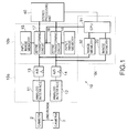
- FIG. 1 the detail of the image input unit 10 of FIG. 3 will be described below.
- the image input unit 10 comprises: an image input part 10 a for inputting a picked-up image; an image adjusting part 10b for carrying out a geometrical transformation, such as rotation and parallel displacement of the image; and a correction operating part 10c for calculating an transforming value for the image.
- the image input part 10a has analog interfaces 11 and 12 for adjusting analog images, which are outputted from the cameras 2 and 3, to downstream input ranges, and A/D converters 13 and 14 for transforming the analog images into digital images having predetermined brightness and gradation (e.g., a gray scale of 256 gradations).
- predetermined brightness and gradation e.g., a gray scale of 256 gradations.
- the image adjusting part 10b has input image memories 15 and 16 for temporarily storing the digitized images, and affine transforming circuits 17 and 18 for carrying out a geometrical transformation, such as rotation and parallel displacement, of the digital images stored in the input image memories 15 and 16 to output the geometrically transformed images to the stereo processing unit 40.
- affine transforming circuits 17 and 18 for carrying out a geometrical transformation, such as rotation and parallel displacement, of the digital images stored in the input image memories 15 and 16 to output the geometrically transformed images to the stereo processing unit 40.
- the affine transforming circuits 17 and 18 carry out corrections when the corresponding points of the images picked up by the cameras 2 and 3 move geometrically from the original positions due to the deviations of the optical axes.
- the internal construction of the affine transforming circuits 17 is shown in FIG. 2.
- the affine transforming circuit 17 comprises: an image memory data interface 20 for writing data into the input image memory 15 and for reading data out of the input image memory 15; an image memory address interface 21 for addressing the input image memory 15; an input image writing address generating circuit 22 for generating an address when the image data outputted from the A/D converter 13 are written in the input image memory 15; an inverse affine transformation reading address generating circuit 23 for generating an address, which is used for reading the image data out of the input image memory 15 to geometrically transform the image, by the inverse affine transformation; and an interpolation operating circuit 24 for carrying out the linear interpolation of data, which have been read by the inverse affine transformation, to output transformed image data.
- the original image before transformation and the transformed image are digital images wherein pixels are arranged in the form of a grid, and the concentration values of the pixels on the transformed image are given by the concentration values of the corresponding pixel positions derived by the inverse affine transformation of the original image.
- the corresponding pixel positions derived by the inverse affine transformation are not generally integer pixel positions, so that the pixels on the transformed image do not correspond to any pixels on the original image. Therefore, the interpolation operating circuit 24 carries out the linear interpolation using the concentration values of four surrounding pixels, to closely derive the concentration values of the pixels on the transformed image.
- image signals outputted from the cameras 2 and 3 e.g., image signals, such as NTSC picture signals, outputted from the cameras 2 and 3 in synchronism with a line synchronizing signal and a frame synchronizing signal, are sampled in a sampling period of a field signal, the affine transforming circuits 17 and 18 transform the sampled image in the next field interval.
- image signals outputted from the cameras 2 and 3 e.g., image signals, such as NTSC picture signals, outputted from the cameras 2 and 3 in synchronism with a line synchronizing signal and a frame synchronizing signal
- the gain offset and so forth of image signals outputted from the cameras 2 and 3 are adjusted to the input ranges of the A/D converters 13 and 14 by means of the analog interfaces 11 and 12.
- the digital image data converted by the A/D converters 13 and 14 are stored in the input image memories 15 and 16 in accordance with addresses generated by the input image writing address generating circuits 22 and 22 of the affine transforming circuits 17 and 18.
- the concentration data at addresses generated by the inverse affine transformation reading address generating circuits 23 and 23 of the affine transforming circuits 17 and 18 are read out of the input image memories 15 and 16.
- the interpolation operations of the concentration data are carried out by means of the interpolation operating circuits 24 and 24 of the affine transforming circuits 17 and 18 to output the transformed images to the stereo processing unit 40.
- the correction values for the variations of optical axes of the cameras 2 and 3, i.e., the image transforming values in the affine transforming circuit 17 and 18, can be obtained from coordinate data of a coincident point measured from a picked-up image, which is obtained by picking up a special adjusting pattern arranged at a known distance (a distance by which a parallax can be inversely calculated).
- a special adjusting pattern arranged at a known distance (a distance by which a parallax can be inversely calculated).
- the correction values are operated by the correction operating part 10c to be fed to the affine transforming circuits 17 and 18 as the image transforming values to automatically make an adjustment.
- the correction operating part 10c comprises a computer having a CPU 31, image memories 32 and 33 and so forth.
- the correction operating part 10c is connected to the A/D converters 13 and 14 of the image input unit 10 via the image memories 32 and 33, and to the stereo processing unit 40. It is noted that the correction operating part 10c may be a part of the stereo processing unit 40 and carry out the correction processing as a background job of the stereo image processing.
- FIG. 5 is an image correcting routine executed by the CPU 31 of the correction operating part 10c every a predetermined period.
- this routine at step S100, the results of a group filter, which are obtained when images of a landscape picked up by the cameras 2 and 3 are processed to extract three-dimensional object data from a distance image, are read out of the stereo processing unit 40, and some small regions for operating correction values are set in the image picked up by the main camera 2, i.e., in a reference image.
- each of the small regions is a region of 16 ⁇ 16 pixels, the half or more of which include corresponding distance image data.
- the small regions three regions including two distant regions at a long distance of about 50 to 60 m and one near region at a short distance of up to about 5 m are selected.
- the two distant regions are spaced from each other so as to have substantially the same distance data.
- the group filter is a software filter for detecting a group having an image deviation similar to those of surrounding pixels to efficiently remove noises included in the distance image.
- Such a group filter is disclosed in Japanese Patent Application No. 9-86877, which is assigned to the present Assignee and incorporated herein by reference.
- step S110 distance data (deviation) are added to the positions of the respective regions of the reference image set at step S100, to define a range for searching the corresponding regions in the image picked up by the sub-camera 3, i.e., in the comparative image.
- this range is searched to derive the positions of the regions at a resolution of one pixel or less (e.g., a resolution of 1/10 pixels) by the sub-pixel processing.
- the position coordinates (Xc1, Yc1) and (Xc2, Yc2) of two distant regions # 1C and # 2C and the position coordinate (Xc3, Yc3) of one near region #3C of the comparative image are derived for the position coordinates (Xr1, Yr1) and (Xr2, Yr2) of two distant regions #1R and #2R and the position coordinate (Xr3, Yr3) of one near region #3R of the reference image.
- a difference between the Y components of the position coordinates of one of the two distant regions on the reference image side and the corresponding distant region on the comparative image side e.g., a difference (Yr1-Yc1) between the Y components of the position coordinate (Xr1, Yr1) of the left distant region # 1R on the reference image side and the position coordinate (Xc1, Yc1) of the corresponding left distant region # 1C on the comparative image side in FIG.
- a Y direction translation correction value i.e., as an image translating transformation value in Y directions, to parallel-displace the image (the comparative image) of the sub-camera 3 in Y directions.
- an X direction translation correction value for the comparative image is derived to be added to the set value of the affine transforming circuit 18 on the comparative image side to parallel-displace the image of the sub-camera 3 in X directions.
- This X direction translation correction value can be given by a deviation Z0 between the reference and comparative images at infinity.
- the deviation Z0 at infinity can be represented by the following formula (1) using a distance d1 to the distant region, a distance d3 to the near region, a deviation Z1 between the reference and comparative images in the distant region, and a deviation Z3 between the reference and comparative images in the near region.
- -Z0 is a translation amount of the comparative image in lateral directions (X directions).
- Z0 (d3 • Z3-d1 • Z1)/(d1-d3)
- the comparative image is rotated so that the position of the Y coordinate of the other region of the comparative image is coincident with that of the reference image. That is, as shown in FIG. 7, the comparative image is rotated about the position coordinate (Xr1, Yr1) of the left distant region # 1R of the reference image so that the Y coordinate value Yc2 of the right distant region # 2C of the comparative image is coincident with the Y coordinate value Yr2 of the right distant region # 2R of the reference image.
- a coordinate (Xc2', Yc2') after rotation can be represented by the following formula (2).
- the angle of rotation ⁇ can be derived by the following formula (6).
- This angle of rotation ⁇ is added to the set value of the affine transforming circuit 18 on the comparative image side as an image rotating transformation value about the coordinate (Xr1, Yr1) to rotate the image (the comparative image) of the sub-camera 3.
- ⁇ sin -1 (A • B-C • (B 2 +C 2 -A 2 ) 1/2 )/(B 2 +C 2 )
- the near region # 3C of the comparative image is also rotated.
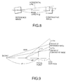
- the base lines of the cameras 2 and 3 are not parallel to the horizontal line of the main camera 2 so that the horizontal line of the main camera 2 is inclined by an angle ⁇ with respect to the base lines as shown in FIG. 8, there is a difference ⁇ Ym - ⁇ Ys between the Y coordinate value Yr3 of the near region # 3R of the reference image and the Y coordinate value Yc3 of the near region #3C of the comparative image after rotation as shown in FIG. 9.
- the rotation by the angle of rotation ⁇ about the coordinate (Xr1, Yr1) on the reference image side is added to the set value in order to remove the difference ⁇ Ym - ⁇ Ys.
- the angle of rotation ⁇ can be derived from the base length B of the cameras 2 and 3 and a deviation ⁇ Y between the centers of the reference and comparative images on a focal plane.
- the deviation ⁇ Y can be derived using the focal point f, the distance d1 to the distant region, the distance d3 to the near region and the difference ⁇ Ym - ⁇ Ys on the basis of the geometrical relationship when the camera system is viewed from side as shown in FIG. 9.
- the deviation ⁇ Y can be derived by the following formula (7) using the difference ⁇ Ym - ⁇ Ys between the deviation ⁇ Ym of the near region from the center of the reference image formed on the CCD surface (image picked-up surface) and the deviation ⁇ Ys of the near region fi-om the center of the comparative image formed on the CCD surface. From the deviation ⁇ Y and the base length B, the angle of rotation ⁇ can be finally derived by the following formula (8).
- ⁇ Y ( ⁇ Ym- ⁇ Ys) • d1 • d3/(f ⁇ (d1-d3))
- the routine goes from the above step S160 to step S170 wherein it is examined whether the angles of rotation ⁇ and ⁇ are sufficiently small to be within a range of allowable values.
- the routine returns to the step S120 wherein the position of the corresponding region of the comparative image is determined by the sub-pixel processing again. Then, the same processing is repeated, and when the angles of rotation ⁇ and ⁇ are sufficiently small below the allowable value, the routine ends.
- the deviations of the optical axes of the cameras 2 and 3 gradually caused in usual use can be automatically corrected while maintaining the operation state in the field.
Applications Claiming Priority (2)
| Application Number | Priority Date | Filing Date | Title |
|---|---|---|---|
| JP06157798A JP4172554B2 (ja) | 1998-03-12 | 1998-03-12 | ステレオカメラの調整装置 |
| JP6157798 | 1998-03-12 |
Publications (3)
| Publication Number | Publication Date |
|---|---|
| EP0942610A2 true EP0942610A2 (fr) | 1999-09-15 |
| EP0942610A3 EP0942610A3 (fr) | 2001-03-07 |
| EP0942610B1 EP0942610B1 (fr) | 2004-06-30 |
Family
ID=13175130
Family Applications (1)
| Application Number | Title | Priority Date | Filing Date |
|---|---|---|---|
| EP99104888A Expired - Lifetime EP0942610B1 (fr) | 1998-03-12 | 1999-03-11 | Système et méthode de réglage de la convergence d'une caméra stéréoscopique |
Country Status (4)
| Country | Link |
|---|---|
| US (1) | US6385334B1 (fr) |
| EP (1) | EP0942610B1 (fr) |
| JP (1) | JP4172554B2 (fr) |
| DE (1) | DE69918347T2 (fr) |
Cited By (11)
| Publication number | Priority date | Publication date | Assignee | Title |
|---|---|---|---|---|
| EP1087205A2 (fr) * | 1999-09-22 | 2001-03-28 | Fuji Jukogyo Kabushiki Kaisha | Télémètre stéréo |
| WO2003035433A1 (fr) * | 2001-10-18 | 2003-05-01 | Siemens Aktiengesellschaft | Systeme et procede pour saisir le nombre d'occupants d'un vehicule |
| EP1085463A3 (fr) * | 1999-09-16 | 2003-10-29 | Fuji Jukogyo Kabushiki Kaisha | Appareil d'ajustement de la déviation positionelle d'images stereo |
| EP1408703A2 (fr) * | 2002-10-10 | 2004-04-14 | Fuji Photo Optical Co., Ltd. | Système électronique de prise d'images stéréoscopiques |
| EP1533653A1 (fr) * | 1999-09-22 | 2005-05-25 | Fuji Jukogyo Kabushiki Kaisha | Système de prise de vue stéreoscopique |
| US7022922B2 (en) | 2001-11-14 | 2006-04-04 | Siemens Aktiengesellschaft | Power switch with a mobile contact element and extinction gas flow that move in an axial direction when activated |
| GB2473247A (en) * | 2009-09-04 | 2011-03-09 | Sony Corp | Aligning camera images using transforms based on image characteristics in overlapping fields of view |
| GB2477333A (en) * | 2010-01-29 | 2011-08-03 | Sony Corp | Stereoscopic camera system with image processor to transform one of stereoscopic pair to give effect of increased stereo base |
| GB2478164A (en) * | 2010-02-26 | 2011-08-31 | Sony Corp | Calculating misalignment between a stereoscopic image pair based on feature positions |
| JP2014072592A (ja) * | 2012-09-28 | 2014-04-21 | Hitachi Automotive Systems Ltd | 撮像装置 |
| CN107867405A (zh) * | 2016-09-27 | 2018-04-03 | 波音公司 | 补偿至少两个飞行器安装相机的相对运动的装置和方法 |
Families Citing this family (51)
| Publication number | Priority date | Publication date | Assignee | Title |
|---|---|---|---|---|
| JP2000276469A (ja) * | 1999-03-23 | 2000-10-06 | Canon Inc | 情報検索装置及びその方法、記憶媒体 |
| JP4428761B2 (ja) * | 1999-07-07 | 2010-03-10 | Hoya株式会社 | ステレオカメラ |
| JP3565749B2 (ja) * | 1999-09-22 | 2004-09-15 | 富士重工業株式会社 | 車載カメラの撮像方向の検査方法およびその検査装置 |
| JP4573977B2 (ja) * | 1999-09-22 | 2010-11-04 | 富士重工業株式会社 | 監視システムの距離補正装置、および監視システムの消失点補正装置 |
| US8369607B2 (en) | 2002-03-27 | 2013-02-05 | Sanyo Electric Co., Ltd. | Method and apparatus for processing three-dimensional images |
| JP3797949B2 (ja) * | 2002-03-28 | 2006-07-19 | 株式会社東芝 | 画像処理装置及びその方法 |
| JP4488804B2 (ja) * | 2004-06-23 | 2010-06-23 | 株式会社トプコン | ステレオ画像の関連付け方法及び3次元データ作成装置 |
| JP4406381B2 (ja) * | 2004-07-13 | 2010-01-27 | 株式会社東芝 | 障害物検出装置及び方法 |
| JP4224449B2 (ja) | 2004-11-30 | 2009-02-12 | 本田技研工業株式会社 | 画像抽出装置 |
| US7590263B2 (en) | 2004-11-30 | 2009-09-15 | Honda Motor Co., Ltd. | Vehicle vicinity monitoring apparatus |
| JP4032052B2 (ja) | 2004-11-30 | 2008-01-16 | 本田技研工業株式会社 | 位置検出装置及びその補正方法 |
| US7599521B2 (en) | 2004-11-30 | 2009-10-06 | Honda Motor Co., Ltd. | Vehicle vicinity monitoring apparatus |
| JP4461091B2 (ja) | 2004-11-30 | 2010-05-12 | 本田技研工業株式会社 | 位置検出装置及びその補正方法 |
| JP4828274B2 (ja) * | 2006-03-27 | 2011-11-30 | 株式会社エヌ・ティ・ティ・データ | 構造物異常判別システム及び構造物異常判別方法ならびにプログラム |
| US20070248260A1 (en) * | 2006-04-20 | 2007-10-25 | Nokia Corporation | Supporting a 3D presentation |
| JP2008040115A (ja) * | 2006-08-04 | 2008-02-21 | Fuji Heavy Ind Ltd | ステレオカメラ |
| US8736672B2 (en) * | 2006-08-24 | 2014-05-27 | Reald Inc. | Algorithmic interaxial reduction |
| JP5234894B2 (ja) * | 2007-06-28 | 2013-07-10 | 富士重工業株式会社 | ステレオ画像処理装置 |
| JP4867837B2 (ja) * | 2007-07-30 | 2012-02-01 | 株式会社島津製作所 | モーショントラッカ装置 |
| JP5031494B2 (ja) * | 2007-09-07 | 2012-09-19 | 株式会社 ニコンビジョン | 望遠鏡システム |
| JP4937933B2 (ja) * | 2008-01-18 | 2012-05-23 | 富士重工業株式会社 | 車外監視装置 |
| WO2011014419A1 (fr) * | 2009-07-31 | 2011-02-03 | 3Dmedia Corporation | Procédés, systèmes et supports de mémorisation lisibles par ordinateur pour création d'images tridimensionnelles (3d) d'une scène |
| US20110025830A1 (en) * | 2009-07-31 | 2011-02-03 | 3Dmedia Corporation | Methods, systems, and computer-readable storage media for generating stereoscopic content via depth map creation |
| US9380292B2 (en) | 2009-07-31 | 2016-06-28 | 3Dmedia Corporation | Methods, systems, and computer-readable storage media for generating three-dimensional (3D) images of a scene |
| JP5444065B2 (ja) * | 2010-03-19 | 2014-03-19 | 富士フイルム株式会社 | 複眼撮像装置およびその制御方法 |
| JP2011250177A (ja) * | 2010-05-27 | 2011-12-08 | Toshiba Corp | カメラモジュール及び画像記録方法 |
| KR101129326B1 (ko) * | 2010-06-16 | 2012-03-27 | 허성용 | 영상 촬영용 광축 정렬 장치 및 광축 정렬 방법 |
| JP5690539B2 (ja) | 2010-09-28 | 2015-03-25 | 株式会社トプコン | 自動離着陸システム |
| WO2012061549A2 (fr) | 2010-11-03 | 2012-05-10 | 3Dmedia Corporation | Procédés, systèmes et produits logiciels informatiques pour créer des séquences vidéo tridimensionnelles |
| JP5682265B2 (ja) * | 2010-12-01 | 2015-03-11 | 株式会社リコー | 測距装置および撮像装置 |
| US8274552B2 (en) | 2010-12-27 | 2012-09-25 | 3Dmedia Corporation | Primary and auxiliary image capture devices for image processing and related methods |
| US10200671B2 (en) | 2010-12-27 | 2019-02-05 | 3Dmedia Corporation | Primary and auxiliary image capture devices for image processing and related methods |
| WO2012092246A2 (fr) | 2010-12-27 | 2012-07-05 | 3Dmedia Corporation | Procédés, systèmes et supports de stockage lisibles par ordinateur permettant d'identifier une carte de profondeur approximative dans une scène et de déterminer une distance de base stéréo pour une création de contenu tridimensionnelle (3d) |
| JP5618840B2 (ja) | 2011-01-04 | 2014-11-05 | 株式会社トプコン | 飛行体の飛行制御システム |
| FR2972061B1 (fr) * | 2011-02-24 | 2013-11-15 | Mobiclip | Procede de calibrage d'un dispositif de prise de vue stereoscopique |
| JP5672112B2 (ja) * | 2011-03-30 | 2015-02-18 | 富士通株式会社 | ステレオ画像較正方法、ステレオ画像較正装置及びステレオ画像較正用コンピュータプログラム |
| US8797387B2 (en) * | 2011-04-27 | 2014-08-05 | Aptina Imaging Corporation | Self calibrating stereo camera |
| JP5775354B2 (ja) | 2011-04-28 | 2015-09-09 | 株式会社トプコン | 離着陸ターゲット装置及び自動離着陸システム |
| JP5718149B2 (ja) * | 2011-05-19 | 2015-05-13 | シャープ株式会社 | 画像補正方法、および立体画像撮影装置 |
| JP5787695B2 (ja) | 2011-09-28 | 2015-09-30 | 株式会社トプコン | 画像取得装置 |
| JP2012022716A (ja) * | 2011-10-21 | 2012-02-02 | Fujifilm Corp | 立体画像処理装置、方法及びプログラム並びに立体撮像装置 |
| EP2757524B1 (fr) * | 2013-01-16 | 2018-12-19 | Honda Research Institute Europe GmbH | Système et procédé de détection de profondeur pour véhicules autonomes |
| US10085001B2 (en) * | 2014-03-21 | 2018-09-25 | Omron Corporation | Method and apparatus for detecting and mitigating mechanical misalignments in an optical system |
| WO2016018411A1 (fr) | 2014-07-31 | 2016-02-04 | Hewlett-Packard Development Company, L.P. | Mesure et correction de désalignement optique |
| US10007998B2 (en) | 2015-03-20 | 2018-06-26 | Ricoh Company, Ltd. | Image processor, apparatus, and control system for correction of stereo images |
| JP6521796B2 (ja) * | 2015-08-26 | 2019-05-29 | 株式会社Subaru | ステレオ画像処理装置 |
| CN107292810B (zh) * | 2016-03-30 | 2020-01-24 | 上海弼智仿生高科技有限公司 | 一种视觉系统的图像处理方法及系统 |
| JP6785092B2 (ja) * | 2016-08-19 | 2020-11-18 | 株式会社Screenホールディングス | 変位検出装置、変位検出方法および基板処理装置 |
| US10796425B1 (en) * | 2016-09-06 | 2020-10-06 | Amazon Technologies, Inc. | Imagery-based member deformation gauge |
| KR101973655B1 (ko) * | 2018-03-05 | 2019-08-26 | 주식회사 디아이블 | 스포츠 코트 자동인식 및 그에 따른 인/아웃 판단 방법 및 장치 |
| JP7109386B2 (ja) * | 2019-01-22 | 2022-07-29 | 日立Astemo株式会社 | 画像処理装置 |
Citations (2)
| Publication number | Priority date | Publication date | Assignee | Title |
|---|---|---|---|---|
| US5726704A (en) * | 1993-08-26 | 1998-03-10 | Matsushita Electric Industrial Co., Ltd. | Stereoscopic image pickup and display apparatus |
| US6118475A (en) * | 1994-06-02 | 2000-09-12 | Canon Kabushiki Kaisha | Multi-eye image pickup apparatus, and method and apparatus for measuring or recognizing three-dimensional shape |
Family Cites Families (9)
| Publication number | Priority date | Publication date | Assignee | Title |
|---|---|---|---|---|
| US6028954A (en) * | 1988-11-18 | 2000-02-22 | Industrial Science & Technology, Kozo Iizuka, Director-General Of Agency | Method and apparatus for three-dimensional position measurement |
| JPH05157557A (ja) | 1991-12-09 | 1993-06-22 | Mitsubishi Electric Corp | 車載用距離検出装置 |
| JPH0814861A (ja) * | 1994-07-01 | 1996-01-19 | Canon Inc | 3次元形状の計測方法及び装置 |
| JPH0843055A (ja) * | 1994-07-29 | 1996-02-16 | Canon Inc | 3次元物体形状認識方法及び装置 |
| JP3103478B2 (ja) * | 1994-06-02 | 2000-10-30 | キヤノン株式会社 | 複眼撮像装置 |
| US5699444A (en) * | 1995-03-31 | 1997-12-16 | Synthonics Incorporated | Methods and apparatus for using image data to determine camera location and orientation |
| US5748199A (en) * | 1995-12-20 | 1998-05-05 | Synthonics Incorporated | Method and apparatus for converting a two dimensional motion picture into a three dimensional motion picture |
| JPH09187038A (ja) * | 1995-12-27 | 1997-07-15 | Canon Inc | 3次元形状抽出装置 |
| JP3792832B2 (ja) | 1997-05-07 | 2006-07-05 | 富士重工業株式会社 | ステレオカメラの調整装置 |
-
1998
- 1998-03-12 JP JP06157798A patent/JP4172554B2/ja not_active Expired - Lifetime
-
1999
- 1999-03-10 US US09/265,379 patent/US6385334B1/en not_active Expired - Lifetime
- 1999-03-11 EP EP99104888A patent/EP0942610B1/fr not_active Expired - Lifetime
- 1999-03-11 DE DE69918347T patent/DE69918347T2/de not_active Expired - Lifetime
Patent Citations (2)
| Publication number | Priority date | Publication date | Assignee | Title |
|---|---|---|---|---|
| US5726704A (en) * | 1993-08-26 | 1998-03-10 | Matsushita Electric Industrial Co., Ltd. | Stereoscopic image pickup and display apparatus |
| US6118475A (en) * | 1994-06-02 | 2000-09-12 | Canon Kabushiki Kaisha | Multi-eye image pickup apparatus, and method and apparatus for measuring or recognizing three-dimensional shape |
Non-Patent Citations (1)
| Title |
|---|
| ZHAO W ET AL: "Effects of camera alignment errors on stereoscopic depth estimates" PATTERN RECOGNITION,PERGAMON PRESS INC. ELMSFORD, N.Y,US, vol. 29, no. 12, 1 December 1996 (1996-12-01), pages 2115-2126, XP004015755 ISSN: 0031-3203 * |
Cited By (20)
| Publication number | Priority date | Publication date | Assignee | Title |
|---|---|---|---|---|
| EP1085463A3 (fr) * | 1999-09-16 | 2003-10-29 | Fuji Jukogyo Kabushiki Kaisha | Appareil d'ajustement de la déviation positionelle d'images stereo |
| EP1087205A3 (fr) * | 1999-09-22 | 2003-01-02 | Fuji Jukogyo Kabushiki Kaisha | Télémètre stéréo |
| EP1533653A1 (fr) * | 1999-09-22 | 2005-05-25 | Fuji Jukogyo Kabushiki Kaisha | Système de prise de vue stéreoscopique |
| US7106365B1 (en) | 1999-09-22 | 2006-09-12 | Fuji Jukogyo Kabushiki Kaisha | Stereo camera apparatus with a main camera and a sub-camera where the sub-camera has a point of view difference from the point of view of the main camera |
| EP1087205A2 (fr) * | 1999-09-22 | 2001-03-28 | Fuji Jukogyo Kabushiki Kaisha | Télémètre stéréo |
| WO2003035433A1 (fr) * | 2001-10-18 | 2003-05-01 | Siemens Aktiengesellschaft | Systeme et procede pour saisir le nombre d'occupants d'un vehicule |
| US7022922B2 (en) | 2001-11-14 | 2006-04-04 | Siemens Aktiengesellschaft | Power switch with a mobile contact element and extinction gas flow that move in an axial direction when activated |
| EP1408703A2 (fr) * | 2002-10-10 | 2004-04-14 | Fuji Photo Optical Co., Ltd. | Système électronique de prise d'images stéréoscopiques |
| EP1408703A3 (fr) * | 2002-10-10 | 2004-10-13 | Fuji Photo Optical Co., Ltd. | Système électronique de prise d'images stéréoscopiques |
| US8427504B2 (en) | 2009-09-04 | 2013-04-23 | Sony Corporation | Method and apparatus for image alignment |
| GB2473247A (en) * | 2009-09-04 | 2011-03-09 | Sony Corp | Aligning camera images using transforms based on image characteristics in overlapping fields of view |
| GB2473247B (en) * | 2009-09-04 | 2015-02-11 | Sony Corp | A method and apparatus for image alignment |
| GB2477333A (en) * | 2010-01-29 | 2011-08-03 | Sony Corp | Stereoscopic camera system with image processor to transform one of stereoscopic pair to give effect of increased stereo base |
| GB2477333B (en) * | 2010-01-29 | 2014-12-03 | Sony Corp | A method and apparatus for creating a stereoscopic image |
| US8494307B2 (en) | 2010-02-26 | 2013-07-23 | Sony Corporation | Method and apparatus for determining misalignment |
| US8538198B2 (en) | 2010-02-26 | 2013-09-17 | Sony Corporation | Method and apparatus for determining misalignment |
| GB2478164A (en) * | 2010-02-26 | 2011-08-31 | Sony Corp | Calculating misalignment between a stereoscopic image pair based on feature positions |
| JP2014072592A (ja) * | 2012-09-28 | 2014-04-21 | Hitachi Automotive Systems Ltd | 撮像装置 |
| CN107867405A (zh) * | 2016-09-27 | 2018-04-03 | 波音公司 | 补偿至少两个飞行器安装相机的相对运动的装置和方法 |
| CN107867405B (zh) * | 2016-09-27 | 2023-04-11 | 波音公司 | 补偿至少两个飞行器安装相机的相对运动的装置和方法 |
Also Published As
| Publication number | Publication date |
|---|---|
| JPH11259632A (ja) | 1999-09-24 |
| US6385334B1 (en) | 2002-05-07 |
| DE69918347D1 (de) | 2004-08-05 |
| EP0942610A3 (fr) | 2001-03-07 |
| DE69918347T2 (de) | 2005-06-30 |
| EP0942610B1 (fr) | 2004-06-30 |
| JP4172554B2 (ja) | 2008-10-29 |
Similar Documents
| Publication | Publication Date | Title |
|---|---|---|
| EP0942610B1 (fr) | Système et méthode de réglage de la convergence d'une caméra stéréoscopique | |
| JP3792832B2 (ja) | ステレオカメラの調整装置 | |
| JP3261115B2 (ja) | ステレオ画像処理装置 | |
| JP3263931B2 (ja) | ステレオマッチング装置 | |
| EP1343332B1 (fr) | Système d'examen des caractéristiques d'une image stéréoscopique | |
| Shah et al. | A simple calibration procedure for fish-eye (high distortion) lens camera | |
| US5706419A (en) | Image capturing and processing apparatus and image capturing and processing method | |
| CN110830781B (zh) | 一种基于双目视觉的投影图像自动校正方法及系统 | |
| JPH11325889A (ja) | ステレオカメラの画像補正装置 | |
| CN110580718B (zh) | 图像装置的校正方法及其相关图像装置和运算装置 | |
| JP2002071309A (ja) | 3次元画像検出装置 | |
| JP3958638B2 (ja) | ステレオ画像処理装置およびステレオ画像処理方法 | |
| JP2000283753A (ja) | ステレオ画像による測距装置 | |
| JP2022003769A (ja) | デジタル画像を整列させること | |
| JP2003304561A (ja) | ステレオ画像処理装置 | |
| JPH11325890A (ja) | ステレオカメラの画像補正装置 | |
| JP2007158695A (ja) | 車載画像処理装置 | |
| JP4172555B2 (ja) | ステレオカメラの調整装置 | |
| CN111179180A (zh) | 影像的修正方法及其装置 | |
| CN115719320A (zh) | 基于遥感影像的倾斜校正稠密匹配方法 | |
| JP4324271B2 (ja) | 画像処理装置およびその方法 | |
| US20220038646A1 (en) | Synchronized camera system having two different cameras | |
| AU2018213100B2 (en) | Apparatus and method for registering recorded images | |
| US11985293B2 (en) | System and methods for calibration of an array camera | |
| JPH10267616A (ja) | キャリブレーション方法およびキャリブレーション装置、並びに補正方法および補正装置 |
Legal Events
| Date | Code | Title | Description |
|---|---|---|---|
| PUAI | Public reference made under article 153(3) epc to a published international application that has entered the european phase |
Free format text: ORIGINAL CODE: 0009012 |
|
| AK | Designated contracting states |
Kind code of ref document: A2 Designated state(s): AT BE CH CY DE DK ES FI FR GB GR IE IT LI LU MC NL PT SE Kind code of ref document: A2 Designated state(s): DE GB |
|
| AX | Request for extension of the european patent |
Free format text: AL;LT;LV;MK;RO;SI |
|
| PUAL | Search report despatched |
Free format text: ORIGINAL CODE: 0009013 |
|
| RIC1 | Information provided on ipc code assigned before grant |
Free format text: 7H 04N 13/00 A |
|
| AK | Designated contracting states |
Kind code of ref document: A3 Designated state(s): AT BE CH CY DE DK ES FI FR GB GR IE IT LI LU MC NL PT SE |
|
| AX | Request for extension of the european patent |
Free format text: AL;LT;LV;MK;RO;SI |
|
| 17P | Request for examination filed |
Effective date: 20010730 |
|
| AKX | Designation fees paid |
Free format text: DE GB |
|
| GRAP | Despatch of communication of intention to grant a patent |
Free format text: ORIGINAL CODE: EPIDOSNIGR1 |
|
| GRAS | Grant fee paid |
Free format text: ORIGINAL CODE: EPIDOSNIGR3 |
|
| GRAA | (expected) grant |
Free format text: ORIGINAL CODE: 0009210 |
|
| AK | Designated contracting states |
Kind code of ref document: B1 Designated state(s): DE GB |
|
| REG | Reference to a national code |
Ref country code: GB Ref legal event code: FG4D |
|
| REF | Corresponds to: |
Ref document number: 69918347 Country of ref document: DE Date of ref document: 20040805 Kind code of ref document: P |
|
| PGFP | Annual fee paid to national office [announced via postgrant information from national office to epo] |
Ref country code: GB Payment date: 20050209 Year of fee payment: 7 |
|
| PLBE | No opposition filed within time limit |
Free format text: ORIGINAL CODE: 0009261 |
|
| STAA | Information on the status of an ep patent application or granted ep patent |
Free format text: STATUS: NO OPPOSITION FILED WITHIN TIME LIMIT |
|
| 26N | No opposition filed |
Effective date: 20050331 |
|
| PG25 | Lapsed in a contracting state [announced via postgrant information from national office to epo] |
Ref country code: GB Free format text: LAPSE BECAUSE OF NON-PAYMENT OF DUE FEES Effective date: 20060311 |
|
| GBPC | Gb: european patent ceased through non-payment of renewal fee |
Effective date: 20060311 |
|
| REG | Reference to a national code |
Ref country code: DE Ref legal event code: R082 Ref document number: 69918347 Country of ref document: DE Representative=s name: MEISSNER BOLTE PATENTANWAELTE RECHTSANWAELTE P, DE Ref country code: DE Ref legal event code: R081 Ref document number: 69918347 Country of ref document: DE Owner name: SUBARU CORPORATION, JP Free format text: FORMER OWNER: FUJI JUKOGYO K.K., TOKIO/TOKYO, JP |
|
| PGFP | Annual fee paid to national office [announced via postgrant information from national office to epo] |
Ref country code: DE Payment date: 20180227 Year of fee payment: 20 |
|
| REG | Reference to a national code |
Ref country code: DE Ref legal event code: R071 Ref document number: 69918347 Country of ref document: DE |