US8736672B2 - Algorithmic interaxial reduction - Google Patents
Algorithmic interaxial reduction Download PDFInfo
- Publication number
- US8736672B2 US8736672B2 US11/509,960 US50996006A US8736672B2 US 8736672 B2 US8736672 B2 US 8736672B2 US 50996006 A US50996006 A US 50996006A US 8736672 B2 US8736672 B2 US 8736672B2
- Authority
- US
- United States
- Prior art keywords
- image
- images
- interaxial
- image collecting
- separation distance
- Prior art date
- Legal status (The legal status is an assumption and is not a legal conclusion. Google has not performed a legal analysis and makes no representation as to the accuracy of the status listed.)
- Active
Links
Images


Classifications
-
- H—ELECTRICITY
- H04—ELECTRIC COMMUNICATION TECHNIQUE
- H04N—PICTORIAL COMMUNICATION, e.g. TELEVISION
- H04N13/00—Stereoscopic video systems; Multi-view video systems; Details thereof
- H04N13/10—Processing, recording or transmission of stereoscopic or multi-view image signals
- H04N13/106—Processing image signals
- H04N13/144—Processing image signals for flicker reduction
-
- H—ELECTRICITY
- H04—ELECTRIC COMMUNICATION TECHNIQUE
- H04N—PICTORIAL COMMUNICATION, e.g. TELEVISION
- H04N13/00—Stereoscopic video systems; Multi-view video systems; Details thereof
- H04N13/10—Processing, recording or transmission of stereoscopic or multi-view image signals
- H04N13/106—Processing image signals
- H04N13/111—Transformation of image signals corresponding to virtual viewpoints, e.g. spatial image interpolation
-
- H—ELECTRICITY
- H04—ELECTRIC COMMUNICATION TECHNIQUE
- H04N—PICTORIAL COMMUNICATION, e.g. TELEVISION
- H04N13/00—Stereoscopic video systems; Multi-view video systems; Details thereof
- H04N13/20—Image signal generators
- H04N13/204—Image signal generators using stereoscopic image cameras
- H04N13/239—Image signal generators using stereoscopic image cameras using two 2D image sensors having a relative position equal to or related to the interocular distance
-
- H—ELECTRICITY
- H04—ELECTRIC COMMUNICATION TECHNIQUE
- H04N—PICTORIAL COMMUNICATION, e.g. TELEVISION
- H04N2213/00—Details of stereoscopic systems
- H04N2213/002—Eyestrain reduction by processing stereoscopic signals or controlling stereoscopic devices
Definitions
- the present invention relates generally to the field of motion picture cinematography, and more specifically to algorithmically reducing the interaxial separation for stereo-pair motion picture or video cinematography to produce lower parallax values.
- a stereoscopic camera In stereoscopic cinematography, two planar cameras are employed to capture two perspective views, one for each eye.
- a stereoscopic camera has two camera heads—one for producing a left perspective, and the other for producing a right perspective.
- the strength or quality of the stereoscopic image is, to a large extent, determined by the separation of the two cameras, or the interaxial separation. The farther apart the camera heads, in other words, the greater their interaxial (distance between lens axes) separation, the stronger the stereoscopic effect. Conversely, the closer the camera heads, the weaker the stereoscopic effect.
- screen parallax is defined as a measure of the distance between left and right corresponding or homologous image points when such points are projected on a screen. It is usually important when shooting stereoscopic images to be sure that the maximum parallax values will, in a typical viewing configuration, not exceed a certain limiting value—namely the average or mean human interpupillary separation for background points. If the value of parallax is too great, discomfort is experienced because the user's eyes are forced to diverge, an experience that does not happen in the visual field when not observing a stereoscopic projected image. A principal way to control the value of parallax is through the adjustment of the camera's interaxial separation, t.
- Adjustability of the interaxial separation enables the cinematographer to control the strength of the stereoscopic image.
- the proper interaxial value must be used to produce a natural-looking image, and the distance of the object from the cameras bears on the interaxial value and hence the quality of the image.
- Selecting the interpupillary separation may be a good starting point, but there are so many exceptions that this rule of thumb is frequently violated, and good quality viewing may be experienced when the cameras are closer or further apart than the interpupillary separation.
- a method for determining an intermediate stereoscopic perspective representation comprises obtaining a first image using a first image collecting device obtaining a second image using a second image collecting device. Some distance physically separates the two recoding devices, and the second image may be combined with the first image to form a stereoscopic image.
- the design further determines the intermediate stereoscopic perspective representation based on aspects of the first image combined with aspects of the second image.
- an apparatus for creating an intermediate stereoscopic perspective representation of a plurality of stereoscopic images comprises a first image collecting device configured to record a first image and a second image collecting device separated by a distance from the first image collecting device and configured to record a second image.
- the second image is configured to be combined with the first image to form a stereoscopic image.
- the apparatus further comprises a processing device configured to compute the intermediate stereoscopic perspective representation based on the first image and the second image.
- FIG. 1 shows a previous stereoscopic camera rig in which the cameras face each other and shoot into an inverted-V mirror set
- FIG. 2 is a previous camera rig in which the left and right cameras are at right angles to each other;
- FIG. 3 is a simplified camera rig according to the teachings provided herein;
- FIG. 4 shows a simplified rig using a virtual interaxial reduction as created algorithmically
- FIG. 5 shows the process flow using the interpolated image to provide a stereo-pair of reduced interaxial separation
- FIG. 6A is a diagrammatic illustration of the eyes of an observer looking at a stereoscopic projected motion picture image in which the corresponding points have a parallax value equal to the interpupillary separation;
- FIG. 6B is a schematic representation of a stereoscopic motion picture projected image in which the parallax value of the corresponding points is greater than the interpupillary separation.
- the present discussion is not directed to describing stereoscopic display or viewing means, but rather is directed to discussion of a method to generally improve the results of image capture, or the ability for a computing or other electronic device to capture an image or images for viewing.
- Stereoscopic cinematography requires two planar cameras to capture two perspective views, one for each eye.
- the reason for two planar cameras is the human viewer. Human beings see with the depth sense binocular stereopsis because they have two eyes that are approximately 2.5 inches apart. The eyes and the brain, to produce binocular stereopsis, combine these two slightly different perspective views of the visual world.
- a stereoscopic camera has two camera heads—one for producing a left perspective, and the other for producing a right perspective.
- a camera with two camera heads is called a stereoscopic camera or rig, and it will be referred to herein in the singular.
- the strength of the stereoscopic image is, to a large extent, determined by the separation of the two cameras, or the interaxial separation. In the nomenclature of stereoscopy this quantity is usually represented as a lowercase and frequently italicized t. The farther apart the camera heads, in other words, the greater their interaxial separation, the stronger the stereoscopic effect. Conversely, the closer the camera heads, the weaker the stereoscopic effect.
- screen parallax is defined as a measure of the distance between left and right corresponding or homologous image points when such points are projected on a screen. If one laid a straight edge or ruler between the two points, the measured distance is defined as parallax.
- the screen surface is 601 , 604 and 605 are the left and right eyes, respectively, and the lens axes of the eyes are lines 602 and 603 .
- the interpupillary separation is given by line 606 .
- FIG. 6A illustrates the case for non-divergent positive parallax in which the left and right homologous points, point 608 and point 609 , respectively, are the parallax distance, which is equal to the interpupillary separation 606 . This replicates the case of viewing an object at a great distance in the real world, or at stereo-optical infinity, because the lens axes of the eyes are parallel.
- Fusion is the process of bringing the corresponding points to the fovea centralis of the left and right retinae, respectively.
- the rotation of the eyes is called vergence.
- the inward rotation is called convergence, and inward rotation ordinarily occurs when viewing the visual world.
- the only time in the visual field that vergence is not convergence (or inward rotation) is when looking at objects at a very great distance, in which case the lens axes of the eyes are parallel.
- Equation (1) is, as stated, a special case of the depth range equation. This is because it is assumed that the background points are at some great distance from the camera. An additional term for distance (not shown) disappears from the denominator in the simplified version shown as Equation (1).
- Comfortable viewing wherein background points are non-divergent, can be achieved by means of controlling the focal length and interaxial separation at the time of photography rather than at the time of projection or post-photography. It is assumed that the choice of distance to the zero parallax plane d z is limited to a certain range since the object of principal interest is preferably at or near the plane of the screen. The magnification of the image is determined at the time of projection and is essentially out of the control of the cinematographer or graphic artists.
- interaxial Since the appearance of the image(s) or look of the shot is, to a large extent, artistically controlled by the choice of focal length, which combined with changing the camera distance from the subject, controls the perspective of the objects, manipulation of the interaxial is the sole useful parameter for parallax control. But the interaxial is typically if not always the most difficult to control photographic parameter for live action photography because of design limitations of the camera rigs related to the width of the camera heads.
- the present design provides a means for reducing interaxial separation by algorithmic rather than by optical or mechanical means.
- a measure that relates screen parallax to retinal disparity is parallax expressed as an angle.
- Retinal disparity is the relationship of corresponding points received at the left and right retinae. Expressing parallax as an angle enables relating the amount of divergence trigonometrically, or by angular measure.
- people sitting close to the screen experience greater divergence than people sitting farther away from the screen.
- people sitting close to the screen may experience the most discomfort. This causes the stereoscopic cinematographer to remember the adage that he should be kind to the people in the front rows of the theater.
- a general-purpose stereoscopic camera is preferably able to vary the interaxial separation.
- a well-designed stereoscopic camera rig for general-purpose cinematography should have the ability to vary the interaxial separation from a small interaxial value to a large interaxial value.
- interaxial separation from about one inch to a foot will cover the vast majority of cases.
- the ability to adjust cameras to vary the interaxial separation is quite beneficial.
- the cameras are positioned on a precision rail or optical positioning device typically employed with camera rig setups, and left and right perspective views can be captured appropriately. Difficulties arise in reducing the interaxial separation because the cameras cannot be brought any closer together than the width of a camera body.
- Providing both reduced and expanded interaxial separations present various challenges. Once the cinematographer varies the distance between the cameras, mechanical and optical tolerance issues must be addressed. Moving cameras makes keeping the lens axes in the same horizontal plane difficult, and maintaining the alignment is a primary requirement. Even a small tilt upward or downward of one axis produces a vertical parallax that will create divergence and eyestrain for the observers.
- rigs For close-up photography, or photography for objects close to the camera, various kinds of rigs are available that can reduce interaxial separation by optical means. Such rigs are clumsy and awkward; they become large because of the optical systems involved, and because of the general bulkiness of having to arrange two cameras at awkward angles.
- the first design is presented in FIG. 1 and represents a previous type of camera rig.
- This device seeks to reduce the camera interaxial separation to at least approximate the human interpupillary distance.
- Two cameras make up the camera rig, cameras 101 and 107 .
- the cameras have a separation or width 110 of a.
- the left camera has a lens 102
- the right camera has lens 106 .
- Both cameras and lenses face into an inverted V-shaped mirror ensemble made up of plane mirrors 104 and 105 .
- Dotted lines 108 and 109 represent the left and right camera lens axes extended as reflected from the mirrors.
- t 1 is indicated as point 111 , where t 1 is the effective interaxial separation and is less than camera width a.
- the arrangement here is one in which the two cameras produce an interaxial separation less than a, by shooting or filming using this inverted V mirror ensemble.
- One difficulty with a rig such as that shown in FIG. 1 is that the reduction in interaxial separation may need to be less than the interpupillary separation for close-up photography. Without this capability, close-up photography (photography of objects close to the camera) results in background homologous points extended beyond the interpupillary distance, thereby creating the divergent condition.
- Depth range Equation (1) shows that for close objects that are set at the zero parallax plane, d z approaches zero, and the maximum parallax points can rapidly increase to unacceptable values.
- FIG. 2 shows a more complex rig using left camera 201 and right camera 204 .
- the left and right cameras are of width a at point 209 , and the left and right camera lenses are lenses 202 and 205 respectively.
- the cameras shoot into or through a beam splitter or pellicle 203 .
- the beam splitter or pellicle 203 is a semi-silvered mirror that allows the right camera 204 to see directly through it, and the left camera 201 to see a reflected image off of the surface of the pellicle 203 .
- the effective interaxial separation is made up of lens axis 206 (shown as 207 after reflection off the surface of the pellicle), as reflected by 203 , in combination with axis 208 for lens 205 which sees directly through pellicle 203 , and is given by t 2 at 210 .
- the advantage of this rig over the previously described is that the interaxial separation may be varied as either camera is translated in a direction orthogonal to the lens axis. By this means t 2 210 may be reduced to 0, or if desired, increased to some larger value.
- FIGS. 1 and 2 In the case of both rigs ( FIGS. 1 and 2 ), careful mechanical/optical alignment is required. In the first case, FIG. 1 , there are limitations with regard to interaxial separation. In the second case of FIG. 2 , the result is a large rig generally unsuitable for many kinds of photography, particularly in situations where a smaller camera is required, such as handheld camera photography.
- the present design changes the interaxial separation without moving either of the two cameras employed in the rig.
- the design allows for an interaxial separation reduction that is less than the width of the camera, to facilitate close-ups (the face, or an object held in the hands, for example) or extreme close-ups.
- the design enables changing interaxial separation without moving cameras based on an algorithm or algorithms using a kind of image processing to extract or interpolate an intermediate perspective view. This process can take place either at the time of photography or during post-production.
- the design presented may also be applied in scientific and medical imaging. It may be difficult to build a stereoscopic laparoscope, for example, in which the interaxial separation can be reduce to produce easy to view images with the appropriate depth content. In such as case the methodology described herein may be applied.
- this disclosure is not limited to digital photography, it is most preferably employed in conjunction with digital cameras that produce electronic files, because such files can be immediately processed in the field without a conversion from film to digital files, and in post-production such files are more conveniently handled. If stereoscopic photography originates on conventional photographic film, the images so photographed need to be converted to digital files to be processed according to these teachings.
- the system receives two images from two cameras and interpolates an intermediate perspective view, as if a camera placed between the left and right cameras had captured the intermediate perspective view.
- This intermediate view can then provide, in conjunction with one of the original views, a stereo-pair having reduced interaxial separation.
- This reduced interaxial separation is employed to reduce the parallax values of corresponding distant points to prevent divergence when the images are viewed on a projection screen.
- the interpolated image provides an intermediate view of appropriate perspective without the requirement that the cameras be moved or translated.
- the intermediate view is derived algorithmically means. Scores of interpolation algorithms have been developed for many purposes over a number of years, and there is a substantial literature on the subject. No particular interpolation algorithm is favored over another in the present design, but it is to be understood that interpolation algorithms are employed to enable and calculate the intermediate view discussed herein.
- the following disclosures pertain to computational algorithms that may be employed to create the intermediate image discussed herein: M. Agrawal and L. Davis, “Window-Based Discontinuity Preserving Stereo,” IEEE Conference on Computer Vision and Pattern Recognition (CVPR), 2004; S. Birchfield and C. Tomasi, “Depth Discontinuities by Pixel-to-Pixel Stereo,” IEEE International Conference on Computer Vision (ICCV), 1998; S. Birchfield and C. Tomasi, “Multiway Cut for Stereo and Motion with Slanted Surfaces,” ICCV, 1999; M. Bleyer and M. Gelautz, “Graph-Based Surface Reconstruction from Stereo Pairs Using Image Segmentation,” Proceedings of the SPIE, vol. 5665, January 2005; M.
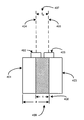
- FIG. 3 shows left camera 301 and right camera 304 , with left lens 302 and right lens 305 .
- the width of the cameras shown at point 307 is given by dimension a.
- the separation between the facing inside surfaces of the cameras at point 309 is given by b. When b is zero, the cameras are as close together as possible and the minimum interaxial separation has been achieved.
- Dashed lines 303 and 306 respectively, represent the lens axes for the left and right cameras.
- Interaxial separation t 3 is shown at point 308 .
- Dimension b at point 309 can vary, but the cameras cannot be separated by a value where b is less than zero. In the case where b is equal to zero, the cameras are at their minimum physical interaxial separation. Such an arrangement may be employed in a handheld camera ensemble for photography from normal shooting distances in a room or set environment, but the requirement might then be, in many instances, to have an interaxial separation in which t 3 is less than distance a. The value of a in this situation may be too large for photography in which objects are close to the camera. On the other hand, when b is a large distance, eight or nine inches or more, then the instrument is relatively flexible. It is then not necessary to physically translate the cameras since the effective interaxial distance can be derived algorithmically.
- the intermediate view can be derived algorithmically either in the field or in post-production to a desired value, such as less than t 3 .
- FIG. 4 the same cameras as in FIG. 3 are shown. However, the cameras are in a “virtual” mode, and are now labeled left camera 401 and right camera 403 . The width of the cameras remains at a.
- the left camera lens 402 and right camera lens 405 are shown, and the left and right lens axes 404 and 406 are also presented.
- Distance 407 represents the interaxial separation t 4 .
- the crosshatched area denoted distance c and called out as region 408 indicates a virtual representation of what would occur if the two cameras could occupy the same space. As shown by region 408 , the interaxial separation reduced by value c to be less than the width of the camera a, or to t 4 .
- the resultant stereo-pair view can be derived algorithmically, with a process flow as given below.
- a firmware version of the algorithmic derivation may be employed to derive the reduced stereo-pair at the time of photography—but because creative choices can be deferred and viewed more effectively, post-production processing may be preferred.
- post-production different persons (cinematographer, director, etc.) have the option of varying the interaxial separation, and the ability to study at leisure which separation produces the best effect.
- a number of different effective interaxial separations can be derived and evaluated based on judgment to determine what the final or “best” interaxial separation setting can be for a particular shot, scene, or image.
- the separation can be varied continuously to coordinate with variations in the zero parallax setting or to coordinate with zooming.
- FIG. 5 the work or the process flow is presented.
- Left and right images A and B form a camera stereo-pair.
- the images are derived at the time of original photography, using two cameras having an established physical separation. Interpolation between the two images A and B occurs so that view C is produced.
- View C represents a view, or camera position, at a specific but essentially any distance between the interaxial separation corresponding to views A and B. For example, C can be three-quarters of the way between A and B, halfway between A and B, or any value between the two views.
- This interpolation can be derived at the time of photography or it can be done in post-production, as previously mentioned.
- Interpolated image C can form a stereo-pair A+C to produce the new stereo-pair # 1 . Alternately, C+B produce new stereo-pair # 2 .
- C may be coupled with original image A or original B, as long as the desired reduced interaxial effect has been achieved by the interpolation.
- interpolation function At the core of the interaxial processing is the interpolation function.
- interpolation different algorithms or methods may be employed, but the simplest would be a straight linear intermediate image formation on a pixel by pixel basis.
- Pixel X comprising red, green, and blue subpixel elements.
- R, G, and B represent the intensities of those subpixels, respectively; these values are typically described on a scale of 0 (minimum intensity) to 255 (maximum intensity).
- Image A representing the left image
- Image B representing the right image
- R b subpixel values (R b , G b , B b )
- a simple linear interpolation algorithm may be employed to calculate intermediate values for those subpixels.
- Pixel X in Image A has RGB values (96, 128, 96)
- Pixel X in Image B has RGB values (224, 0, 32)
- Pixel X in the intermediate image would have RGB values that are 33% of the way from Image A values to Image B values:
- Non linear interpolation, processing for movement or blurring, or other applicable stereoscopic interpolation techniques may be employed, and other optical parameters, including but not limited to luminance and chrominance may be employed.
- digital linear pixel values may be employed and rounding or truncation may be employed. For example, if the left image has a red pixel Y that is on (1) and the right image has a red pixel Y that is off (0), and the pixel can only be on or off, an intermediate image desired to be 75 per cent toward the left image may result in the intermediate pixel Y being on (1).
- the design uses interpolation, or the foregoing algorithmic process or processes, to create images having different interaxial separations with a standard or fixed interaxial distance between the two source cameras.
- interaxial separation can be reduced either at the time of photography or in post-production so that an interpolated or intermediate view can be used to derive, in conjunction with either the original left or right image, a new stereo-pair.
- the new stereo-pair has, in effect, a reduced interaxial separation compared with the physically set rig interaxial.
- Such a reduced interaxial separation is effective for eliminating divergence of background homologous points upon projection, or can be used to vary the interaxial separation even continuously, if required, in order to obviate camera head translation and thereby eliminate calibration setup which is costly and time-consuming.
- Such an algorithmically derived reduction in interaxial may also be used to achieve an aesthetically desirable result that would not be otherwise possible given the limitations of the camera rig.
- the above algorithm phase has derived a mapping of image points, that mapping, along with pixel data from each of the source images, can be utilized to assemble an intermediate stereo view.
- some horizontal offset will indicate the parallax setting of that scene element. That horizontal offset might be a positive number (indicating what is known as positive parallax), zero (indicating zero parallax), or a negative number (negative parallax).
- the amount of parallax offset to applied to any given scene element may be determined based on the full parallax offset for that particular scene element in the two original stereo pairs as well as the view position of the desired intermediate view.
- the parallax offset amount for the scene element in the new view, relative to the left-eye view would simply be (n*P).
- the doorknob in the scene has a parallax offset, between the left-eye and the right-eye views, of 15 pixels, and an intermediate image is 33% of the way between the left-eye and the right-eye view is desired, the doorknob appears in the intermediate stereo image with a parallax offset of 15*0.33, or 5 pixels, relative to the appearance of that feature in the left-eye view.
- n is greater than 50%, making that intermediate view closer to the right-eye view, it may be better to calculate the intermediate parallax offset relative to the right-eye view, which would be (1 ⁇ n)*( ⁇ P).
Landscapes
- Engineering & Computer Science (AREA)
- Multimedia (AREA)
- Signal Processing (AREA)
- Testing, Inspecting, Measuring Of Stereoscopic Televisions And Televisions (AREA)
- Image Processing (AREA)
- Studio Devices (AREA)
Abstract
Description
P m =Mft/d z (1)
R n=(R a*(1−n))+(R b *n) (2)
G n=(G a*(1−n))+(G b *n) (3)
B n=(B a*(1−n))+(B b *n) (4)
R n=(96*(0.67))+(224*0.33)=138 (5)
G n=(128*(0.67))+(0*0.33)=86 (6)
B n=(96*(0.67))+(32*0.33)=75 (7)
Claims (21)
Priority Applications (2)
| Application Number | Priority Date | Filing Date | Title |
|---|---|---|---|
| US11/509,960 US8736672B2 (en) | 2006-08-24 | 2006-08-24 | Algorithmic interaxial reduction |
| PCT/US2007/018430 WO2008024316A2 (en) | 2006-08-24 | 2007-08-20 | Algorithmic interaxial reduction |
Applications Claiming Priority (1)
| Application Number | Priority Date | Filing Date | Title |
|---|---|---|---|
| US11/509,960 US8736672B2 (en) | 2006-08-24 | 2006-08-24 | Algorithmic interaxial reduction |
Publications (2)
| Publication Number | Publication Date |
|---|---|
| US20080049100A1 US20080049100A1 (en) | 2008-02-28 |
| US8736672B2 true US8736672B2 (en) | 2014-05-27 |
Family
ID=39107331
Family Applications (1)
| Application Number | Title | Priority Date | Filing Date |
|---|---|---|---|
| US11/509,960 Active US8736672B2 (en) | 2006-08-24 | 2006-08-24 | Algorithmic interaxial reduction |
Country Status (2)
| Country | Link |
|---|---|
| US (1) | US8736672B2 (en) |
| WO (1) | WO2008024316A2 (en) |
Cited By (2)
| Publication number | Priority date | Publication date | Assignee | Title |
|---|---|---|---|---|
| US20160381341A1 (en) * | 2015-06-24 | 2016-12-29 | Intel Corporation | View interpolation for visual storytelling |
| US20220406003A1 (en) * | 2021-06-17 | 2022-12-22 | Fyusion, Inc. | Viewpoint path stabilization |
Families Citing this family (84)
| Publication number | Priority date | Publication date | Assignee | Title |
|---|---|---|---|---|
| US7791640B2 (en) * | 2004-01-23 | 2010-09-07 | Olympus Corporation | Electronic camera and image generating apparatus generating stereo image |
| US9124877B1 (en) * | 2004-10-21 | 2015-09-01 | Try Tech Llc | Methods for acquiring stereoscopic images of a location |
| US7917100B2 (en) | 2005-09-21 | 2011-03-29 | Broadcom Corporation | Method and system for a double search user group selection scheme with range in TDD multiuser MIMO downlink transmission |
| GB0522968D0 (en) | 2005-11-11 | 2005-12-21 | Popovich Milan M | Holographic illumination device |
| GB0718706D0 (en) | 2007-09-25 | 2007-11-07 | Creative Physics Ltd | Method and apparatus for reducing laser speckle |
| JP4291862B2 (en) * | 2007-07-04 | 2009-07-08 | 稔 稲葉 | 3D television system and 3D television receiver |
| DE202007010389U1 (en) * | 2007-07-24 | 2007-09-27 | Maier, Florian | Device for automatic positioning of coupled cameras for plastic imaging |
| US8115825B2 (en) * | 2008-02-20 | 2012-02-14 | Apple Inc. | Electronic device with two image sensors |
| USD603445S1 (en) | 2009-03-13 | 2009-11-03 | X6D Limited | 3D glasses |
| USD624952S1 (en) | 2008-10-20 | 2010-10-05 | X6D Ltd. | 3D glasses |
| USRE45394E1 (en) | 2008-10-20 | 2015-03-03 | X6D Limited | 3D glasses |
| USD666663S1 (en) | 2008-10-20 | 2012-09-04 | X6D Limited | 3D glasses |
| US8542326B2 (en) | 2008-11-17 | 2013-09-24 | X6D Limited | 3D shutter glasses for use with LCD displays |
| CA2684513A1 (en) * | 2008-11-17 | 2010-05-17 | X6D Limited | Improved performance 3d glasses |
| DE102008061760A1 (en) * | 2008-12-12 | 2010-06-17 | Daimler Ag | Device for monitoring an environment of a vehicle |
| GB2480193B (en) | 2009-01-19 | 2015-01-21 | Minoru Inaba | Stereoscopic video imaging display system |
| USD646451S1 (en) | 2009-03-30 | 2011-10-04 | X6D Limited | Cart for 3D glasses |
| US9335604B2 (en) | 2013-12-11 | 2016-05-10 | Milan Momcilo Popovich | Holographic waveguide display |
| US11726332B2 (en) | 2009-04-27 | 2023-08-15 | Digilens Inc. | Diffractive projection apparatus |
| USD650956S1 (en) | 2009-05-13 | 2011-12-20 | X6D Limited | Cart for 3D glasses |
| USD672804S1 (en) | 2009-05-13 | 2012-12-18 | X6D Limited | 3D glasses |
| JP5182229B2 (en) * | 2009-06-02 | 2013-04-17 | ソニー株式会社 | Image processing apparatus, image processing method, and program |
| US9341846B2 (en) | 2012-04-25 | 2016-05-17 | Rockwell Collins Inc. | Holographic wide angle display |
| USD669522S1 (en) | 2010-08-27 | 2012-10-23 | X6D Limited | 3D glasses |
| USD671590S1 (en) | 2010-09-10 | 2012-11-27 | X6D Limited | 3D glasses |
| USD692941S1 (en) | 2009-11-16 | 2013-11-05 | X6D Limited | 3D glasses |
| JP5515729B2 (en) * | 2009-12-24 | 2014-06-11 | ソニー株式会社 | Camera adapter device and camera control method |
| JP5413184B2 (en) | 2009-12-24 | 2014-02-12 | ソニー株式会社 | Camera system and camera control method |
| USD662965S1 (en) | 2010-02-04 | 2012-07-03 | X6D Limited | 3D glasses |
| US9192286B2 (en) * | 2010-03-12 | 2015-11-24 | Viking Systems, Inc. | Stereoscopic visualization system |
| EP2393298A1 (en) * | 2010-06-03 | 2011-12-07 | Zoltan Korcsok | Method and apparatus for generating multiple image views for a multiview autostereoscopic display device |
| USD664183S1 (en) | 2010-08-27 | 2012-07-24 | X6D Limited | 3D glasses |
| GB201017413D0 (en) * | 2010-10-14 | 2010-12-01 | Lindsay Michael D | Stereo 3D |
| FR2967324B1 (en) * | 2010-11-05 | 2016-11-04 | Transvideo | METHOD AND DEVICE FOR CONTROLLING THE PHASING BETWEEN STEREOSCOPIC CAMERAS |
| KR101694292B1 (en) * | 2010-12-17 | 2017-01-09 | 한국전자통신연구원 | Apparatus for matching stereo image and method thereof |
| US9237331B2 (en) * | 2011-01-18 | 2016-01-12 | Disney Enterprises, Inc. | Computational stereoscopic camera system |
| WO2012136970A1 (en) | 2011-04-07 | 2012-10-11 | Milan Momcilo Popovich | Laser despeckler based on angular diversity |
| US9536312B2 (en) | 2011-05-16 | 2017-01-03 | Microsoft Corporation | Depth reconstruction using plural depth capture units |
| US10670876B2 (en) | 2011-08-24 | 2020-06-02 | Digilens Inc. | Waveguide laser illuminator incorporating a despeckler |
| US20140204455A1 (en) | 2011-08-24 | 2014-07-24 | Milan Momcilo Popovich | Wearable data display |
| WO2016020630A2 (en) | 2014-08-08 | 2016-02-11 | Milan Momcilo Popovich | Waveguide laser illuminator incorporating a despeckler |
| US8619148B1 (en) * | 2012-01-04 | 2013-12-31 | Audience, Inc. | Image correction after combining images from multiple cameras |
| WO2013102759A2 (en) | 2012-01-06 | 2013-07-11 | Milan Momcilo Popovich | Contact image sensor using switchable bragg gratings |
| WO2014055058A1 (en) * | 2012-02-15 | 2014-04-10 | Thomson Licensing | Video conference system and method for maintaining participant eye contact |
| WO2013167864A1 (en) | 2012-05-11 | 2013-11-14 | Milan Momcilo Popovich | Apparatus for eye tracking |
| JP5745183B2 (en) * | 2012-07-30 | 2015-07-08 | オリンパス株式会社 | Imaging apparatus and imaging method |
| USD711959S1 (en) | 2012-08-10 | 2014-08-26 | X6D Limited | Glasses for amblyopia treatment |
| US9933684B2 (en) * | 2012-11-16 | 2018-04-03 | Rockwell Collins, Inc. | Transparent waveguide display providing upper and lower fields of view having a specific light output aperture configuration |
| EP2765774A1 (en) * | 2013-02-06 | 2014-08-13 | Koninklijke Philips N.V. | System for generating an intermediate view image |
| WO2014188149A1 (en) | 2013-05-20 | 2014-11-27 | Milan Momcilo Popovich | Holographic waveguide eye tracker |
| CN104240217B (en) * | 2013-06-09 | 2017-08-11 | 上海兴芯微电子科技有限公司 | Binocular camera image depth information acquisition methods and device |
| US9727772B2 (en) | 2013-07-31 | 2017-08-08 | Digilens, Inc. | Method and apparatus for contact image sensing |
| US9565416B1 (en) | 2013-09-30 | 2017-02-07 | Google Inc. | Depth-assisted focus in multi-camera systems |
| US9544574B2 (en) | 2013-12-06 | 2017-01-10 | Google Inc. | Selecting camera pairs for stereoscopic imaging |
| US10359736B2 (en) | 2014-08-08 | 2019-07-23 | Digilens Inc. | Method for holographic mastering and replication |
| US10241330B2 (en) | 2014-09-19 | 2019-03-26 | Digilens, Inc. | Method and apparatus for generating input images for holographic waveguide displays |
| WO2016046514A1 (en) | 2014-09-26 | 2016-03-31 | LOKOVIC, Kimberly, Sun | Holographic waveguide opticaltracker |
| WO2016048402A2 (en) | 2014-09-26 | 2016-03-31 | Reald | Multiscopic image capture system |
| WO2016113533A2 (en) | 2015-01-12 | 2016-07-21 | Milan Momcilo Popovich | Holographic waveguide light field displays |
| CN107873086B (en) | 2015-01-12 | 2020-03-20 | 迪吉伦斯公司 | Environmentally isolated waveguide display |
| US10330777B2 (en) | 2015-01-20 | 2019-06-25 | Digilens Inc. | Holographic waveguide lidar |
| US9632226B2 (en) | 2015-02-12 | 2017-04-25 | Digilens Inc. | Waveguide grating device |
| US10459145B2 (en) | 2015-03-16 | 2019-10-29 | Digilens Inc. | Waveguide device incorporating a light pipe |
| US10591756B2 (en) | 2015-03-31 | 2020-03-17 | Digilens Inc. | Method and apparatus for contact image sensing |
| WO2017060665A1 (en) | 2015-10-05 | 2017-04-13 | Milan Momcilo Popovich | Waveguide display |
| CN109073889B (en) | 2016-02-04 | 2021-04-27 | 迪吉伦斯公司 | Holographic waveguide optical tracker |
| WO2017162999A1 (en) | 2016-03-24 | 2017-09-28 | Popovich Milan Momcilo | Method and apparatus for providing a polarization selective holographic waveguide device |
| JP6734933B2 (en) | 2016-04-11 | 2020-08-05 | ディジレンズ インコーポレイテッド | Holographic Waveguide Device for Structured Light Projection |
| WO2018102834A2 (en) | 2016-12-02 | 2018-06-07 | Digilens, Inc. | Waveguide device with uniform output illumination |
| WO2018129398A1 (en) | 2017-01-05 | 2018-07-12 | Digilens, Inc. | Wearable heads up displays |
| JP7018566B2 (en) * | 2017-04-28 | 2022-02-14 | パナソニックIpマネジメント株式会社 | Image pickup device, image processing method and program |
| JP7399084B2 (en) | 2017-10-16 | 2023-12-15 | ディジレンズ インコーポレイテッド | System and method for doubling the image resolution of pixelated displays |
| TWI766898B (en) * | 2017-11-08 | 2022-06-11 | 創新服務股份有限公司 | 3D Medical Microscope |
| WO2019136476A1 (en) | 2018-01-08 | 2019-07-11 | Digilens, Inc. | Waveguide architectures and related methods of manufacturing |
| US20190212588A1 (en) | 2018-01-08 | 2019-07-11 | Digilens, Inc. | Systems and Methods for Manufacturing Waveguide Cells |
| JP7404243B2 (en) | 2018-01-08 | 2023-12-25 | ディジレンズ インコーポレイテッド | Systems and methods for high-throughput recording of holographic gratings in waveguide cells |
| CA2993561C (en) * | 2018-01-31 | 2020-06-30 | Synaptive Medical (Barbados) Inc. | System for three-dimensional visualization |
| EP4372451A3 (en) | 2018-03-16 | 2024-08-14 | Digilens Inc. | Holographic waveguides incorporating birefringence control and methods for their fabrication |
| US11402801B2 (en) | 2018-07-25 | 2022-08-02 | Digilens Inc. | Systems and methods for fabricating a multilayer optical structure |
| EP3924759A4 (en) | 2019-02-15 | 2022-12-28 | Digilens Inc. | Methods and apparatuses for providing a holographic waveguide display using integrated gratings |
| JP2022525165A (en) | 2019-03-12 | 2022-05-11 | ディジレンズ インコーポレイテッド | Holographic Waveguide Backlights and Related Manufacturing Methods |
| US20200386947A1 (en) | 2019-06-07 | 2020-12-10 | Digilens Inc. | Waveguides Incorporating Transmissive and Reflective Gratings and Related Methods of Manufacturing |
| EP4004646A4 (en) | 2019-07-29 | 2023-09-06 | Digilens Inc. | Methods and apparatus for multiplying the image resolution and field-of-view of a pixelated display |
| KR20220054386A (en) | 2019-08-29 | 2022-05-02 | 디지렌즈 인코포레이티드. | Vacuum Bragg grating and manufacturing method thereof |
Citations (19)
| Publication number | Priority date | Publication date | Assignee | Title |
|---|---|---|---|---|
| US2990759A (en) * | 1959-04-27 | 1961-07-04 | Frank M Marcosky | Binocular adapter for cameras |
| US3574295A (en) * | 1968-06-29 | 1971-04-13 | Olympus Optical Co | Device for taking stereoscopic photograph in a stereoscopic microscope |
| US4557570A (en) * | 1983-09-26 | 1985-12-10 | Walt Disney Productions | Camera assembly for three-dimensional photography |
| US4650305A (en) * | 1985-12-19 | 1987-03-17 | Hineslab | Camera mounting apparatus |
| US5063441A (en) * | 1990-10-11 | 1991-11-05 | Stereographics Corporation | Stereoscopic video cameras with image sensors having variable effective position |
| US5416510A (en) * | 1991-08-28 | 1995-05-16 | Stereographics Corporation | Camera controller for stereoscopic video system |
| US5424773A (en) * | 1993-01-29 | 1995-06-13 | Kawai Musical Inst. Mfg. Co., Ltd. | Apparatus and method for generating a pseudo camera position image from a plurality of video images from different camera positions using a neural network |
| US5646679A (en) * | 1994-06-30 | 1997-07-08 | Canon Kabushiki Kaisha | Image combining method and apparatus |
| US5764871A (en) * | 1993-10-21 | 1998-06-09 | Eastman Kodak Company | Method and apparatus for constructing intermediate images for a depth image from stereo images using velocity vector fields |
| US5765871A (en) | 1995-02-09 | 1998-06-16 | Empire Industries, Inc. | Children's riding toys |
| EP1085769A2 (en) * | 1999-09-15 | 2001-03-21 | Sharp Kabushiki Kaisha | Stereoscopic image pickup apparatus |
| US6233004B1 (en) * | 1994-04-19 | 2001-05-15 | Canon Kabushiki Kaisha | Image processing method and apparatus |
| US6346965B1 (en) * | 1995-02-07 | 2002-02-12 | Agilent Technologies, Inc | High resolution imaging system for simultaneous acquisition of two high aspect ratio object fields |
| US6366281B1 (en) * | 1996-12-06 | 2002-04-02 | Stereographics Corporation | Synthetic panoramagram |
| US6385334B1 (en) * | 1998-03-12 | 2002-05-07 | Fuji Jukogyo Kabushiki Kaisha | System and method for adjusting stereo camera |
| US6384859B1 (en) * | 1995-03-29 | 2002-05-07 | Sanyo Electric Co., Ltd. | Methods for creating an image for a three-dimensional display, for calculating depth information and for image processing using the depth information |
| US6549650B1 (en) * | 1996-09-11 | 2003-04-15 | Canon Kabushiki Kaisha | Processing of image obtained by multi-eye camera |
| US20030185421A1 (en) * | 2002-03-28 | 2003-10-02 | Kabushiki Kaisha Toshiba | Image processing apparatus and method |
| US20040218809A1 (en) * | 2003-05-02 | 2004-11-04 | Microsoft Corporation | Cyclopean virtual imaging via generalized probabilistic smoothing |
-
2006
- 2006-08-24 US US11/509,960 patent/US8736672B2/en active Active
-
2007
- 2007-08-20 WO PCT/US2007/018430 patent/WO2008024316A2/en active Application Filing
Patent Citations (19)
| Publication number | Priority date | Publication date | Assignee | Title |
|---|---|---|---|---|
| US2990759A (en) * | 1959-04-27 | 1961-07-04 | Frank M Marcosky | Binocular adapter for cameras |
| US3574295A (en) * | 1968-06-29 | 1971-04-13 | Olympus Optical Co | Device for taking stereoscopic photograph in a stereoscopic microscope |
| US4557570A (en) * | 1983-09-26 | 1985-12-10 | Walt Disney Productions | Camera assembly for three-dimensional photography |
| US4650305A (en) * | 1985-12-19 | 1987-03-17 | Hineslab | Camera mounting apparatus |
| US5063441A (en) * | 1990-10-11 | 1991-11-05 | Stereographics Corporation | Stereoscopic video cameras with image sensors having variable effective position |
| US5416510A (en) * | 1991-08-28 | 1995-05-16 | Stereographics Corporation | Camera controller for stereoscopic video system |
| US5424773A (en) * | 1993-01-29 | 1995-06-13 | Kawai Musical Inst. Mfg. Co., Ltd. | Apparatus and method for generating a pseudo camera position image from a plurality of video images from different camera positions using a neural network |
| US5764871A (en) * | 1993-10-21 | 1998-06-09 | Eastman Kodak Company | Method and apparatus for constructing intermediate images for a depth image from stereo images using velocity vector fields |
| US6233004B1 (en) * | 1994-04-19 | 2001-05-15 | Canon Kabushiki Kaisha | Image processing method and apparatus |
| US5646679A (en) * | 1994-06-30 | 1997-07-08 | Canon Kabushiki Kaisha | Image combining method and apparatus |
| US6346965B1 (en) * | 1995-02-07 | 2002-02-12 | Agilent Technologies, Inc | High resolution imaging system for simultaneous acquisition of two high aspect ratio object fields |
| US5765871A (en) | 1995-02-09 | 1998-06-16 | Empire Industries, Inc. | Children's riding toys |
| US6384859B1 (en) * | 1995-03-29 | 2002-05-07 | Sanyo Electric Co., Ltd. | Methods for creating an image for a three-dimensional display, for calculating depth information and for image processing using the depth information |
| US6549650B1 (en) * | 1996-09-11 | 2003-04-15 | Canon Kabushiki Kaisha | Processing of image obtained by multi-eye camera |
| US6366281B1 (en) * | 1996-12-06 | 2002-04-02 | Stereographics Corporation | Synthetic panoramagram |
| US6385334B1 (en) * | 1998-03-12 | 2002-05-07 | Fuji Jukogyo Kabushiki Kaisha | System and method for adjusting stereo camera |
| EP1085769A2 (en) * | 1999-09-15 | 2001-03-21 | Sharp Kabushiki Kaisha | Stereoscopic image pickup apparatus |
| US20030185421A1 (en) * | 2002-03-28 | 2003-10-02 | Kabushiki Kaisha Toshiba | Image processing apparatus and method |
| US20040218809A1 (en) * | 2003-05-02 | 2004-11-04 | Microsoft Corporation | Cyclopean virtual imaging via generalized probabilistic smoothing |
Non-Patent Citations (42)
| Title |
|---|
| A. Colombari, A. Fusiello, & V. Murion, "Continuous Parallax Adjustment for 3D-TV", 2d IEEE Eur. Conf. on Visual Media Production (Dec. 2005). * |
| A. Criminisi, et al., "Efficient Dense-Stereo and Novel-View Synthesis for Gaze Manipulation in One-to-One Teleconferencing," Microsoft Research Technicial Report, Sep. 2003. |
| A. Criminisi, et al., "Efficient Dense-Stereo with Occlusions and New View Synthesis by Four State DP for Gaze Correction," (IJVC), Jan. 2007. |
| Automatic software control of display parameters for stereoscopic graphics images Robert A. Akka, Proc. SPIE 1669, 31 (Jun. 1992). * |
| C. L. Zitnick, et al., "High-Quality Video View Interpolation Using a Layered Representation," ACM SIGGRAPH and ACM Trans. on Graphics, pp. 600-608, vol. 23, Issue 3, Aug. 2004. |
| C. Sun, "Fast Stereo Matching Using Rectangular Subregioning and 3D Maximum-Surface Technigues," CVPR Stereo Workshop, 2001; IJCV, Apr. 2002. |
| D. Scharstein, et al., "A Taxonomy and Evaluation of Dense Two-Frame Stereo Correspondence Algorithms," IJCV, pp. 7-42, vol. 47, No. 1-3, Apr. 2002. |
| H. Hirschmuller, "Improvements in Real-Time Correlation-Based Stereo Vision," CVPR Stereo Workshop, 2001; IJVC, Dec. 2001. |
| H. Mayer, "Analysis of Means to Improve Cooperative Disparity Estimation," Int'l Society for Photogrammetry and Remote Sensing (ISPRS), Sep. 2003. |
| J. Konrad, "Enhancement of Viewer Comfort in Stereoscopic Viewing: Parallax Adjustment", 3639 Proc. SPIE 179-90 (May 1999). * |
| J. Shao, "Combination of Stereo, Motion and Rendering for 3D Footage Display," CVPR Stereo Workshop, 2001; IJCV, Dec. 2001. |
| J. Sun, et al., "Stereo Matching Using Belief Propagation," PAMI, pp. 787-800, vol. 25, Jul. 2003. |
| J. Sun, et al., "Symmetric Stereo Matching for Occlusion Handling," CVPR, Jun. 2005. |
| J.C. Kim, et al., "A Dense Stereo Matching Using Two-Pass Dynamic Programming with Generalized Ground Control Points," CVPR, Jun. 2005. |
| J.Y. Chang, et al., "Stereo Matching Using Iterated Graph Cuts and Mean Shift Filtering," Asian Conf. on Computer Vision (ACCV), Jun. 2006. |
| J.Y. Goulermas, et al., "A Collective-Based Adaptive Symbiotic Model for Surface Reconstruction in Area-Based Stereo," IEEE, vol. 7 (5), pp. 482-502, Oct. 2003. |
| K. Muhlmann, et al., "Calculating Dense Disparity Maps from Color Stereo Images, an Efficient Implementation," CVPR Stereo Workshop, 2001; IJCV, Apr. 2002. |
| K.J. Yoon et al., "Locally Adaptive Support-Weight Approach for Visual Correspondence Search," CVPR, Jun. 2005. |
| L. Hong, "Segment-Based Stereo Matching Using Graph Cuts," CVPR, Jun. 2004. |
| L. Lipton, "Foundations of the Stereoscopic Cinema: A Study in Depth" chs. 3, 6, appendices (1982). * |
| L. Zhang, D. Wang, & A. Vincent, "An Adaptive Object-Based Reconstruction of Intermediate Views from Stereoscopic Images", 3 Proc. of 2001 Int'l Conf. on Image Processing 923-26 (Oct. 2001). * |
| M. Agrawal, et al., "Window-Based Discontinuity Preserving Stereo," IEEE Conference on Computer Vision and Pattern Recognition (CVPR), Jun. 2004. |
| M. Bleyer, et al., "A Layered Stereo Algorithm Using Image Segmentation and Global Visibility Constraints," IEEE (ICIP), pp. 2997-3000, Oct. 2004. |
| M. Gong, et al., "Multi-Baseline Stereo Matching Using Genetic Algorithm," CVPR Stereo Workshop, Dec. 2001. |
| M. Gong, et al., "Near Real-Time Reliable Stereo Matching Using Programmable Graphics Hardware," CVPR, Jun. 2005. |
| M.H. Lin, et al., "Surfaces with Occlusions from Layered Stereo," Ph.D. Thesis, Stanford University, Jun. 2003. |
| Notification of Transmittal of International Preliminary Report on Patentability mailed Feb. 3, 2009 for PCT/US07/018430. |
| O, Veksler, "Stereo Matching by Compact Windows Via Minimum Ratio Cycle," ICCV, 2001, pp. 540-547, vol. 2, Jul. 2001. |
| O. Veksler, "Fast Variable Window for Stereo Correspondence Using Integral Images," CVPR, Jun. 2003. |
| O. Veksler, "Stereo Correspondence by Dynamic Programming on a Tree," CVPR, Jun. 2005. |
| S. Birchfield, et al., "Depth Discontinuities by Pixel-to-Pixel Stereo," IEEE International Conference on Computer Vision (ICCV), Dec. 1999. |
| S. Birchfield, et al., "Multiway Cut for Stereo and Motion with Slanted Surfaces," CCV, Sep. 1999. |
| S. Forstmann, et al., "Real-Time Stereo by Using Dynamic Programming," CVPR Workshop on Real-Time 3D Sensors and Their Use, Jun. 2004. |
| S. Roy, et al., "A Maximum-Flow Formulation of the N-Camera Stereo Correspondence Problem," ICCV, Jan. 1998. |
| S.H. Lee, et al., "Hierarchical Stochastic Diffusion for Disparity Estimation," CVPR Stereo Workshop, 2001; IJVC, Dec. 2002. |
| V. Kolmogorov, et al., "Computing Visual Correspondence with Occlusions Using Graph Cuts," ICCV, vol. 2, pp. 508-515, Jul. 2001. |
| V. Kolmogorov, et al., "Multi-Camera Scene Reconstruction Via Graph Cuts," Eurpoean Conference on Computer Vision (ECCV), May 2002. |
| Wattie, John. "Principles of stereoscopic photography using an ordinary camera". May 2, 2006. . * |
| Wattie, John. "Principles of stereoscopic photography using an ordinary camera". May 2, 2006. <http://nzphoto.tripod.com/starea/stereotake.htm>. * |
| Y. Boykov, et al., "Fast Approximate Energy Minimization Via Graph Cuts," IEEE (PAMI), vol. 23, No. 11, pp. 1222-1239, Nov. 2001. |
| Y. Deng, et al., "A Symmetric Patch-Based Correspondence Model for Occlusion Handling," ICCV, Oct. 2005. |
| Y. Wei, et al., "Region-Based Progressive Stereo Matching," CVPR, Jun. 2004. |
Cited By (3)
| Publication number | Priority date | Publication date | Assignee | Title |
|---|---|---|---|---|
| US20160381341A1 (en) * | 2015-06-24 | 2016-12-29 | Intel Corporation | View interpolation for visual storytelling |
| US10701282B2 (en) * | 2015-06-24 | 2020-06-30 | Intel Corporation | View interpolation for visual storytelling |
| US20220406003A1 (en) * | 2021-06-17 | 2022-12-22 | Fyusion, Inc. | Viewpoint path stabilization |
Also Published As
| Publication number | Publication date |
|---|---|
| US20080049100A1 (en) | 2008-02-28 |
| WO2008024316A3 (en) | 2008-10-16 |
| WO2008024316A2 (en) | 2008-02-28 |
Similar Documents
| Publication | Publication Date | Title |
|---|---|---|
| US8736672B2 (en) | Algorithmic interaxial reduction | |
| US11869205B1 (en) | Techniques for determining a three-dimensional representation of a surface of an object from a set of images | |
| US10430994B1 (en) | Techniques for determining a three-dimensional textured representation of a surface of an object from a set of images with varying formats | |
| US8063930B2 (en) | Automatic conversion from monoscopic video to stereoscopic video | |
| JP5432365B2 (en) | Stereo imaging device and stereo imaging method | |
| JP2018515825A (en) | LIDAR stereo fusion live-action 3D model virtual reality video | |
| US20140002612A1 (en) | Stereoscopic shooting device | |
| JP5444452B2 (en) | Stereo imaging device and stereo imaging method | |
| JPWO2013099169A1 (en) | Stereo camera | |
| WO2008029345A1 (en) | Method for determining a depth map from images, device for determining a depth map | |
| US20150379720A1 (en) | Methods for converting two-dimensional images into three-dimensional images | |
| JP5491617B2 (en) | Stereo imaging device and stereo imaging method | |
| EP3935602B1 (en) | Processing of depth maps for images | |
| WO2018032841A1 (en) | Method, device and system for drawing three-dimensional image | |
| CA2540538C (en) | Stereoscopic imaging | |
| Lin et al. | A low-cost portable polycamera for stereoscopic 360 imaging | |
| Gurrieri et al. | Stereoscopic cameras for the real-time acquisition of panoramic 3D images and videos | |
| JPH08116556A (en) | Image processing method and device | |
| Ince | Correspondence Estimation and Intermediate View Reconstruction | |
| Lagendijk et al. | Stereoscopic image processing | |
| KR100400209B1 (en) | Apparatus for generating three-dimensional moving pictures from tv signals | |
| Audu et al. | Generation of three-dimensional content from stereo-panoramic view | |
| CN115334296A (en) | Stereoscopic image display method and display device | |
| Baldacci et al. | Stereo-browsing from Calibrated Cameras. | |
| Soni et al. | Development of 3D endoscope for minimum invasive surgical system |
Legal Events
| Date | Code | Title | Description |
|---|---|---|---|
| AS | Assignment |
Owner name: REAL D, CALIFORNIA Free format text: ASSIGNMENT OF ASSIGNORS INTEREST;ASSIGNORS:LIPTON, LENNY;AKKA, ROBERT;REEL/FRAME:018242/0877;SIGNING DATES FROM 20060822 TO 20060823 Owner name: REAL D, CALIFORNIA Free format text: ASSIGNMENT OF ASSIGNORS INTEREST;ASSIGNORS:LIPTON, LENNY;AKKA, ROBERT;SIGNING DATES FROM 20060822 TO 20060823;REEL/FRAME:018242/0877 |
|
| AS | Assignment |
Owner name: REALD INC.,CALIFORNIA Free format text: MERGER;ASSIGNOR:REAL D;REEL/FRAME:024294/0658 Effective date: 20100408 Owner name: REALD INC., CALIFORNIA Free format text: MERGER;ASSIGNOR:REAL D;REEL/FRAME:024294/0658 Effective date: 20100408 |
|
| AS | Assignment |
Owner name: CITY NATIONAL BANK, AS ADMINISTRATIVE AGENT, CALIF Free format text: PATENT SECURITY AGREEMENT;ASSIGNOR:REALD, INC.;REEL/FRAME:028146/0006 Effective date: 20120419 |
|
| STCF | Information on status: patent grant |
Free format text: PATENTED CASE |
|
| AS | Assignment |
Owner name: REALD INC., CALIFORNIA Free format text: RELEASE FROM PATENT SECURITY AGREEMENTS AT REEL/FRAME NO. 28146/0006;ASSIGNOR:CITY NATIONAL BANK;REEL/FRAME:038216/0436 Effective date: 20160322 |
|
| AS | Assignment |
Owner name: HIGHBRIDGE PRINCIPAL STRATEGIES, LLC, NEW YORK Free format text: SECURITY INTEREST;ASSIGNORS:REALD INC.;STEREOGRAPHICS CORPORATION;COLORLINK INC.;AND OTHERS;REEL/FRAME:038243/0526 Effective date: 20160322 |
|
| MAFP | Maintenance fee payment |
Free format text: PAYMENT OF MAINTENANCE FEE, 4TH YR, SMALL ENTITY (ORIGINAL EVENT CODE: M2551) Year of fee payment: 4 |
|
| AS | Assignment |
Owner name: JEFFERIES FINANCE LLC, AS COLLATERAL AGENT, NEW YORK Free format text: SECURITY INTEREST;ASSIGNORS:REALD INC.;RHOMBUS INTERMEDIATE HOLDINGS, LP;REALD HOLDINGS, INC;AND OTHERS;REEL/FRAME:047723/0767 Effective date: 20181130 Owner name: JEFFERIES FINANCE LLC, AS COLLATERAL AGENT, NEW YO Free format text: SECURITY INTEREST;ASSIGNORS:REALD INC.;RHOMBUS INTERMEDIATE HOLDINGS, LP;REALD HOLDINGS, INC;AND OTHERS;REEL/FRAME:047723/0767 Effective date: 20181130 |
|
| AS | Assignment |
Owner name: JEFFERIES FINANCE LLC, AS COLLATERAL AGENT, NEW YORK Free format text: SECURITY INTEREST;ASSIGNORS:REALD INC.;RHOMBUS INTERMEDIATE HOLDINGS, LP;REALD HOLDINGS, INC;AND OTHERS;REEL/FRAME:047740/0085 Effective date: 20181130 Owner name: JEFFERIES FINANCE LLC, AS COLLATERAL AGENT, NEW YO Free format text: SECURITY INTEREST;ASSIGNORS:REALD INC.;RHOMBUS INTERMEDIATE HOLDINGS, LP;REALD HOLDINGS, INC;AND OTHERS;REEL/FRAME:047740/0085 Effective date: 20181130 Owner name: REALD DDMG ACQUISITION, LLC, CALIFORNIA Free format text: RELEASE BY SECURED PARTY;ASSIGNOR:HPS INVESTMENT PARTNERS, LLC, AS COLLATERAL AGENT;REEL/FRAME:047741/0621 Effective date: 20181130 Owner name: REALD INC., CALIFORNIA Free format text: RELEASE BY SECURED PARTY;ASSIGNOR:HPS INVESTMENT PARTNERS, LLC, AS COLLATERAL AGENT;REEL/FRAME:047741/0621 Effective date: 20181130 Owner name: STEREOGRAPHICS CORPORATION, CALIFORNIA Free format text: RELEASE BY SECURED PARTY;ASSIGNOR:HPS INVESTMENT PARTNERS, LLC, AS COLLATERAL AGENT;REEL/FRAME:047741/0621 Effective date: 20181130 Owner name: COLORLINK, INC., CALIFORNIA Free format text: RELEASE BY SECURED PARTY;ASSIGNOR:HPS INVESTMENT PARTNERS, LLC, AS COLLATERAL AGENT;REEL/FRAME:047741/0621 Effective date: 20181130 |
|
| AS | Assignment |
Owner name: HPS INVESTMENT PARTNERS, LLC, AS THE SUCCESSOR-IN-INTEREST, NEW YORK Free format text: SECURITY INTEREST;ASSIGNOR:JEFFERIES FINANCE LLC, AS COLLATERAL AGENT;REEL/FRAME:052622/0104 Effective date: 20200506 Owner name: CORTLAND CAPITAL MARKET SERVICES LLC, AS THE SUCCESSOR COLLATERAL AGENT, ILLINOIS Free format text: ASSIGNMENT OF SECURITY INTEREST IN COLLATERAL;ASSIGNOR:JEFFERIES FINANCE LLC, AS COLLATERAL AGENT;REEL/FRAME:052623/0086 Effective date: 20200506 |
|
| AS | Assignment |
Owner name: COLORLINK, INC., CALIFORNIA Free format text: RELEASE OF SECURITY INTEREST RECORDED AT REEL/FRAME 047740/0085;ASSIGNOR:CORTLAND CAPITAL MARKET SERVICES, LLC;REEL/FRAME:054593/0247 Effective date: 20201120 Owner name: REALD DDMG ACQUISITION, LLC, CALIFORNIA Free format text: RELEASE OF SECURITY INTEREST RECORDED AT REEL/FRAME 047740/0085;ASSIGNOR:CORTLAND CAPITAL MARKET SERVICES, LLC;REEL/FRAME:054593/0247 Effective date: 20201120 Owner name: RHOMBUS INTERMEDIATE HOLDINGS, LP, CALIFORNIA Free format text: RELEASE OF SECURITY INTEREST RECORDED AT REEL/FRAME 047740/0085;ASSIGNOR:CORTLAND CAPITAL MARKET SERVICES, LLC;REEL/FRAME:054593/0247 Effective date: 20201120 Owner name: REALD INC., CALIFORNIA Free format text: RELEASE OF SECURITY INTEREST RECORDED AT REEL/FRAME 047740/0085;ASSIGNOR:CORTLAND CAPITAL MARKET SERVICES, LLC;REEL/FRAME:054593/0247 Effective date: 20201120 Owner name: REALD SPARK, LLC, CALIFORNIA Free format text: RELEASE OF SECURITY INTEREST RECORDED AT REEL/FRAME 047740/0085;ASSIGNOR:CORTLAND CAPITAL MARKET SERVICES, LLC;REEL/FRAME:054593/0247 Effective date: 20201120 |
|
| MAFP | Maintenance fee payment |
Free format text: PAYMENT OF MAINTENANCE FEE, 8TH YR, SMALL ENTITY (ORIGINAL EVENT CODE: M2552); ENTITY STATUS OF PATENT OWNER: SMALL ENTITY Year of fee payment: 8 |