WO2008029345A1 - Method for determining a depth map from images, device for determining a depth map - Google Patents
Method for determining a depth map from images, device for determining a depth map Download PDFInfo
- Publication number
- WO2008029345A1 WO2008029345A1 PCT/IB2007/053550 IB2007053550W WO2008029345A1 WO 2008029345 A1 WO2008029345 A1 WO 2008029345A1 IB 2007053550 W IB2007053550 W IB 2007053550W WO 2008029345 A1 WO2008029345 A1 WO 2008029345A1
- Authority
- WO
- WIPO (PCT)
- Prior art keywords
- point
- matching
- depth map
- windows
- image
- Prior art date
Links
Classifications
-
- G—PHYSICS
- G06—COMPUTING; CALCULATING OR COUNTING
- G06T—IMAGE DATA PROCESSING OR GENERATION, IN GENERAL
- G06T17/00—Three dimensional [3D] modelling, e.g. data description of 3D objects
-
- G—PHYSICS
- G06—COMPUTING; CALCULATING OR COUNTING
- G06T—IMAGE DATA PROCESSING OR GENERATION, IN GENERAL
- G06T7/00—Image analysis
- G06T7/50—Depth or shape recovery
- G06T7/55—Depth or shape recovery from multiple images
-
- G—PHYSICS
- G06—COMPUTING; CALCULATING OR COUNTING
- G06T—IMAGE DATA PROCESSING OR GENERATION, IN GENERAL
- G06T7/00—Image analysis
- G06T7/60—Analysis of geometric attributes
Definitions
- the invention relates to a method for determining a depth map from images obtained from different orientations using window-based matching for a point of the image.
- the invention also relates to a device for determining a depth map from images obtained from different orientations using window-based matching for a point of the image.
- depth map For a number of applications it is desirable to determine a depth map from images. Examples of such applications include systems that make it possible to compute images of the scene viewed from interactively controllable orientations, image compression, inspection etc.
- the task of recovering depth maps from stereo imagery is often crucial for a wide range of applications such as 3D displays, quality control at manufacturing, autonomous navigation and object recognition.
- depth of a point in an image refers to the distance between the viewpoint and the plane through the point and perpendicular to the optical axis of camera.
- a depth of an image point can be determined from the amount of translation of the position of the image point. If the image is obtained by point projection, the translation is proportional to the amount of displacement of the camera and inversely proportional to the depth of the part of an image.
- a matching window is used wherein the position of the point of interest is scanned over all points of the window. If a matching window is set asymmetrically around a pixel of interest so that the matching window does not to cover the object boundary, boundary overreach does not appear. The pixel of interest is scanned over the total set of matching windows. Finding the minimum value of the resultant SSSD (Sum of SSD, where SSD is the Sum of Squared differences) gives the disparity estimate for the point.
- the known method provides for a solution for the boundary overreach problem.
- the solution comes, however, at the cost of the need for a large number of computations.
- another problem occurs: smooth disparity surfaces are destroyed and many stepwise squares are observed in such smooth disparity surfaces.
- the problems in smooth disparity surfaces are countered in the known method by implementing a boundary detection method and processing the boundary regions differently from the non-boundary regions.
- the known method requires a large amount of computing power and a rather complex algorithm.
- a number of candidate disparity values is calculated for each point to provide for a provisional depth map wherein to each point more than one candidate disparity value is attributed, where after a further depth map is calculated by minimizing for each point at least the z-component of a norm of a sum of unit vectors pointing from the candidate disparity values for neighboring points to said point.
- the known method is based on a 'winner-takes-all' strategy, i.e. for each point a single best disparity value is calculated. This requires a high accuracy, which requires large amounts of computing power. Even so, the accuracy is only as good as the particular choice of matching windows, i.e. if a particular problem is associated with the choice of matching windows, the problem will persist.
- the key feature of the method in accordance with the invention is a re-calculation of disparity estimates using the candidates as a regularizing space.
- a noisy provisional depth map is made where for each point several candidate disparity values are calculated. For such calculation only a limited calculating power is needed.
- a smoothing operation is thereafter performed to provide each point with a z- value.
- the further depth map is calculated by computing the unit vectors pointing from neighboring 3D points (within the neighborhood and coming from the different super-imposed multi-candidate datasets) to a point, and then finding the disparity that minimizes at said point at least the z-component of a norm of a sum of these unit vectors. This is done for each point of the part of the surface. "Each point” refers to the point of the part of the image for which a further depth map is to be made.
- the number of points within the calculation for the part of the image will usually be equivalent to the number of pixels, wherein to each pixel a point is attributed. "Each point" is not to be misconstrued as to mean 'each point' in a mathematical sense for which there are an infinite number. Neighboring means within the concept of the invention within a given range around the point of interest. In preferred embodiments a norm of the sum of the unit vectors is minimized. If the interest lies mainly in recovering fronto-parallel surfaces minimizing only the z- component of the norm of the sum of unit vectors could be an adequate procedure.
- the sum of the unit vectors is a weighted sum, wherein the weight for each unit vectors within the calculation is a function of distance to the point of interest. This will improve the accuracy.
- the disparity value of a point of interest is more likely to be similar to the disparity value of near-neighboring points than to points further away from the point of interest.
- the set of matching comprises one or more matching windows for which the point of interest is eccentrically located in respect of the matching window. While square blocks are the most commonly used shapes for matching windows, eccentrically positioned shapes for matching windows are more suitable for locking on particular image features such us horizontal and vertical edges. The fact that they are not centered at the point of interest in the image allows at least one of the windows to properly match near occluding boundaries.
- a check is performed to delete from the calculation unit vectors, which differ more than a threshold value from the average.
- Aberrant candidate disparity values i.e. candidate disparity values far outside the normal range due to some computational error, are then less likely to negatively influence the outcome.
- the threshold values may be a fixed value or be calculated on the basis of the other values or may be related to a spread calculation.
- the set of matching windows is a substantially orthogonal set of matching windows.
- Substantially orthogonal matching windows are matching windows wherein the overlap in pixels between the windows is less than 1 A of the number of pixels per window.
- the number of matching windows is four and the matching windows form a cross.
- a cross is a simple arrangement, which has shown to give good results.
- the number of matching windows is eight, wherein the windows are comprised of two foursomes, one foursome being the left hand or right hand version of the windows in the other foursome, each forming a cross.
- Using one foursome of matching windows may introduce a slight left to right or right to left bias. By using two foursomes this bias can be eliminated.
- the matching windows are substantially triangular.
- Fig. 1 shows the geometry of part of an image and two orientations
- Fig. 2 shows an image of a part of an image
- Fig. 3 A shows a flow-chart of a method for making a depth map.
- Fig. 3B illustrates a part of the method in accordance with the invention.
- Fig. 4 illustrates, in one dimension, along a line the resulting provisional depth map.
- Fig. 5 illustrates a further step within the method of the invention.
- Fig. 6 illustrates a set of matching windows as described in the prior art.
- Figs. 7 to 13 illustrate various embodiments of sets of matching windows useable for the method of the invention.
- Fig. 14 illustrates a method in accordance with the invention
- Figs. 15 and 16 illustrate devices in accordance with the invention.
- Fig. 17 illustrates results of the method in accordance with the invention.
- Figs. 18A to 18D further illustrate results of the method in accordance with the invention.
- Fig. 1 shows the geometry of a part of an image 10 and two orientations 12a,b.
- a part of an image may be for instance a person, or any object within the image.
- the present invention relates to a method for providing a depth map for an image.
- a depth map can be seen as attributing a z-value, i.e. a depth value, to points of objects.
- the position where points 14, 15 on the part of an image will be visible in the image are projections 16a,b, 17a,b of points 14, 15.
- the projections can be illustrated by drawing lines 19a-d from the points 14, 15 through the orientations 12a,b to an image plane 18.
- orientations 12a,b have been selected in a plane parallel to the image plane 18, but the invention is not limited to such a selection of orientations 12a,b.
- the intersections between these lines 19a-d and the image plane 18 illustrate the positions where the points 14, 15 of the part of an image 10 will be visible in images.
- a change of viewpoint 12a,b results in a translation of the position 16a,b 17a,b where a point 14, 15 on the part of an image will be visible in the image plane 18.
- This translation is inversely proportional to the depth "z" between the viewpoint and the point and proportional to the amount of change in the position of the viewpoint.
- the translation will be different for points 14, 15 of the part of an image 10 that have different depths "z" from the orientations 12a, b.
- Fig. 2 shows an image 20 containing a region 22 where a part of an image is visible.
- translation vectors 23a,b, 25a,b are shown by which the positions where points of the part of an image that are visible in the image 20 will be translated in response to a movement of the viewpoint. It will be noted that the translation vectors 25a,b will be larger for points of the part of an image that are closer to the viewpoint than for points that are further from the viewpoint.
- the translations will be the same.
- the amplitude of translation "D" of the position where a point is visible will be proportional to A+Bu, where u is a coordinate of the position where the point is visible along the axis perpendicular to the line 26.
- the direction of translation is opposite to the direction of movement of the viewpoint.
- the Figs. 1 and 2 illustrate a situation wherein two cameras are used. To determine a depth map more than two cameras may be used. Using more than two cameras increases the accuracy and reduces the chance that background objects are occluded by objects in the foreground.
- FIG. 3 A schematically shows a flow-chart of a part of a method for making a depth map for an image or at least for a part of an image.
- the camera optics are positioned at a first and second viewpoint respectively, from which a first and second image is obtained respectively.
- a pixel in the first image is selected.
- a match is found between the images using matching windows.
- step 35 of the flow chart to said pixel a z-value is attributed using the results of step 34, i.e. the match of the windows.
- the accuracy has to be high, which leads to the choice of rather large matching windows. Such relatively large matching windows, however, are incapable of catching small details due to their size.
- Fig. 3B illustrates a part of the method in accordance with the invention.
- a set of relatively small eccentric matching windows are used to provide for each point a number of candidate disparity values (z-value 1, z-value2, z-value3 etc). No definitive decision is taken for any point; to each point more than one candidate disparity value is attributed. All the candidate disparity values combined provide for a noisy depth map.
- Fig. 4 illustrates, in one dimension, wherein along a line the candidate disparity (i.e. the z-value) is shown, the resulting provisional depth map.
- the disparity values for two different colors are calculated.
- the two different values are schematically indicated by the filled and open circles.
- Fig. 5 illustrates the next step within the method of the invention.
- a scheme as shown in Fig. 5 is used. For each pixel the depth value that minimizes a norm of the sum of the unit vectors pointing from the reconstructed samples to the candidate point is calculated. In the case the depth value is far from the surface the norm of the sum of these vectors is large (a) but as we hit the surface it is expected to be at or near the minimum. Within the framework of this description this is also called a 'surface filter', i.e. a specific filtering is performed on the provisional noisy depth map.
- the provisional noisy depth map comprises for each point in the part of the image for which the method is used several candidate disparity values.
- the sum of the unit vectors is in itself a vector.
- the norm of a vector can be mathematically understood as the "strength" of this vector.
- the strength of this vector which is the sum of all these unit vectors is minimized.
- the surface map is reached if this strength is low.
- the size of the neighborhood N can be kept small while surface extraction remains robust because of the redundancy coming from the different depth estimators (the different window matching configurations). If we are mostly interested in recovering fronto-parallel surfaces we can minimize only the z-component of (1) which is less expensive computationally.
- the Neighborhood N can also be set by attributing weights to points, wherein the weight is a function of the distance between the points
- W(P;) is a function of the distance between points P; and the point P, decreasing in value as the distance increases.
- the calculation is done for each point of the surface. How many points there are in the calculation will usually be equal to the number of pixels, i.e. to each pixel a point is attributed and for that point the z-value is calculated by minimizing the norm of the sum of unit vectors. This makes calculation relatively easy.
- the surface filter can be shown to extract robustly disparities but to avoid the over-smoothing of depth discontinuities and for better recovery of small details we also include an image-matching constraint.
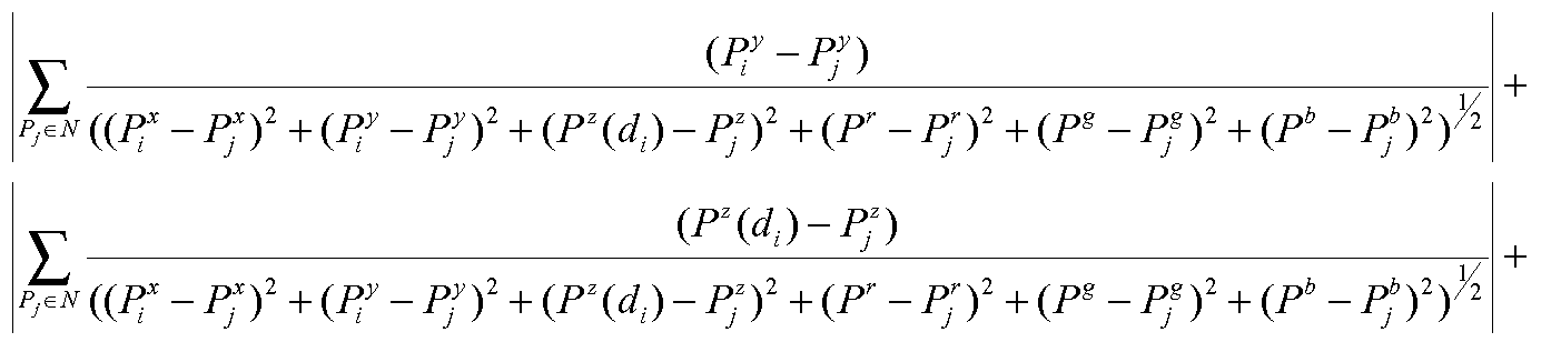
- image-matching constraint we can use any local image similarity criterion. For example we can employ SSD over a very small window. The final criterion that is minimized locally is:
- E(i) S(Ci 1 ) + 1.SSD(Ci 1 ) (2) with ⁇ a factor that balances smooth disparity areas extraction with accurate boundary recovery. Optimization is performed by simply scanning between the minimum and maximum allowed discrete disparity values and finding the disparity that minimizes E(i) .
- this can be seen as a combined method minimizing a combination of the SSD for a point and the norm of the sum of the unit vectors from neighboring points.
- a norm of the sum of unit vectors is minimized but on the constraint that E(i) which is given by the norm of the sum plus the SSD at that point is minimized.
- Fig. 6 illustrates a set of matching windows as described in the cited prior art article. 25 windows are used, each window comprising 25 pixels.
- the pixel 61 for which the z-value is being determined, called "the point of interest" is represented by the black square.
- a standard matching window of 5*5 pixels is used and the pixel of interest is scanned over all point of the standard window. This provides 25 matching windows 62. In Fig. 4 these 25 matching windows are represented by the 5*5 areas of grey squares. Large amounts of calculations will have to be performed.
- Fig. 7 illustrates a set of matching windows as used in the method and device of the invention.
- Fig. 7 a set of four rectangular 5*2 matching windows, substantially orthogonally oriented, is used. The overlap between the matching windows is small.
- Fig. 8 illustrates a further example of a set of windows.
- Fig. 9 illustrates yet another example of a set of windows used in a method and device in accordance with the invention. In this case two sets of four matching windows are used.
- Fig. 10 illustrates yet another example of a set of windows used in a method and device in accordance with the invention.
- Fig. 11 illustrates yet a further example.
- Figs. 12 and 13 illustrate yet a further embodiment of the invention. In the latter examples a set of 8 triangular windows is used.
- matching windows are square.
- the matching windows are non-square, since non-square shaped windows such as rectangular or triangular matching windows are more suitable for locking on particular image features such us horizontal and vertical edges (for rectangular matching windows or triangular as shown in Fig. 11) or edges at 45 degrees (for the triangular matching windows).
- the examples shown in Figs. 7, 8 and 9 show matching windows of substantially rectangular shape. The windows are oriented orthogonal to each other and form, in combination, a cross-shape. These matching windows, as do the matching windows shown in Fig. 9, show edges along the vertical and horizontal direction. Such rectangular shaped matching windows, oriented along the vertical and horizontal direction, are most preferred.
- the matching windows have the same shape and form foursomes of shapes, wherein the shape is oriented and wherein the shapes of each matching window is related to the shape of another matching window and may be obtained by a 90, 180 or 270 degree rotation of another one of the matching windows.
- the sets of Figs. 7 to 13 show such arrangements, wherein each set of matching windows is derived from one (Figs. 7, 8, 9 and 10) or two (Figs. 9, 12) basic oriented forms which are rotated by 90, 180 and 270 degrees to provide the other forms.
- a balance is stricken by employing small relatively thin matching windows that are mutually oriented in orthogonal directions to generate disparity candidates. This scheme provides, on the basis of the provisional depth map a further depth map.
- the calculation may be further optimized by a number of preferred refinements:
- a check is performed to delete from the calculation of S(D) those unit vectors that differ more than a threshold value from the average.
- Aberrant candidate disparity values i.e. candidate disparity values due to some computational error, are then less likely to negatively influence the outcome.
- the threshold values may be a fixed value or be calculated on the basis of the other values or may be related to a spread calculation. - Different schemes are possible to reject false matches and to detect occluded regions.
- a simple scheme is a straightforward Left-Right/Right-Left consistency check. This will insure the uniqueness of the obtained correspondences and allows the labeling of occlusion areas.
- Outlier rejection and occlusion detection will produce holes in the further depth map, i.e. areas for which there is no disparity value.
- a color-based averaging This consists of computing the average (within a local neighborhood) of the disparities that correspond to color pixels close to the color at our site (R 1 , G 1 , B 1 ) .
- a non-linear filter can be used to recompute the depth at a site i at a hole as follows:
- T c being the color difference threshold
- This filter can be used iteratively and has the advantage of re-aligning the boundaries of the depth maps with those of the corresponding color image, which is very important for 3D rendering applications.
- the choice of including a color difference threshold is dictated by the desire to have sharp depth discontinuities that match the actual image discontinuities. In practice this choice has proven to work well.
- Fig. 14 illustrates a method in accordance with the invention in more detail.
- Fig. 14 illustrates 4 modules 141 to 144; the first two modules 141 and 142 are part of the method of the invention in its broadest scope.
- the later two modules 143 and 144 are part of preferred embodiments and are optional.
- a provisional depth map is generated using a window based matching.
- This provisional depth map comprising more than one candidate disparity value for each point, is sent to a surface filter module 142.
- the surface filter module applies a surface filter to the provisional depth map by minimizing at least the z-component of the norm of a sum of unit vectors pointing from the candidate disparity values for neighboring points to said point. This provided for a further depth map.
- Additional modules 143 and 144 which are optional, provide for outlier/occlusion detection and subsequent hole filing.
- the end product is a final depth map.
- a device in accordance with the invention comprises an input for inputting image data obtained from different orientations and a determinator (142) for determining a provisional depth map from the image data received by the input using window-based matching for a point of the image, wherein in the determinator a set of matching windows is used for the point of the image to generate candidate disparity values for the points, wherein the matching windows of the set are eccentrically positioned in respect of the points, wherein device further comprises a surface filter (142) arranged for providing a further depth map on the basis of the provisional depth map by minimizing for each point at least the z-component of the norm of a sum of unit vectors pointing from the candidate disparity values for neighboring points to said point.
- Fig. 15 illustrates a device in accordance with the invention.
- images are taken by two cameras.
- the cameras may record color images, or monochrome images or X-ray images or infrared images.
- Each of the camera provide two sets of data, wherein each set of data represents a two dimensional image, in the Figure illustrated by Dl(xl,yl) and D2(x2,y2), i.e. two two-dimensional data sets.
- the cameras take the images form different orientations.
- the device comprises an input I for inputting the images taken from different orientations and a determinator 141.
- the determinator provides for a provisional depth map which is sent to a surface filter 142.
- the surface filter 142 provides for a further depth map. This further depth map may be further improved by outlier rejection/occlusion detection and image based hole filling.
- a z- value is attributed using the further or final depth map.
- the data from the cameras comprises data on the mutual orientation of the camera's
- the determinator has means to determine the mutual orientation of the camera's or the camera's comprise means to communicate such mutual orientation to the determinator, or the determinator comprises means for inputting such data (for instance by hand), or the set-up of the camera's is fixed so that the mutual orientation is known. Taking of images by the cameras is preferably synchronized.
- the device has an output OP.
- the output data stream D(x,y,z) is a data stream that comprises both the x and the y coordinate of points, as well as the z-coordinate, i.e. the depth map.
- This output data stream D(x,y,z) may be sent to a recording device for instance to record the data stream on a DVD data carrier or any other data carrier, or the output data stream D(x,y,z) may be sent to a three-dimensional display device for displaying three dimensional images.
- Fig. 15 illustrates a device comprising recording devices such as cameras.
- Fig. 16 illustrates a device which has an input for a data carrier, such as for instance a DVD, upon which the data Dl(xl,yl) and D2(x2,y2) as well as data on the mutual orientation of the camera's (D(caml, cam2) are stored.
- the device in accordance with the invention reads the data and provides an output data stream D(x,y,z).
- Preferred embodiments of a device in accordance with the invention comprise means for determining the depth map in accordance with any one or any combination of the above mentioned preferred embodiments of the method, for instance that the matching windows or non-square.
- a device in accordance with the invention may comprise means for recording images, i.e. the device may include the cameras for taking the images, wherein the cameras send the data on the image to the mentioned input.
- the device may also receive data from recording devices.
- determinator filter etc. is to be broadly understood and to comprise e.g. any piece of hardware (such as a determinator), any circuit or sub-circuit designed for performing a determination, selection or matching function as described as well as any piece of soft ware (computer program or sub program or set of computer programs, or program code(s)) designed or programmed to perform a determination, selection or matching operation in accordance with the invention as well as any combination of pieces of hardware and software acting as such, alone or in combination, without being restricted to the below given exemplary embodiments.
- One program may combine several functions.
- Fig. 17 illustrate results of the method in accordance with the invention.
- the first two images are left and right images
- the last Figure gives an idea of the depth map, wherein the grey value is an indication of the depth.
- the results show a very good performance in both extracting depth within low-textured areas and high accuracy at the depth discontinuities.
- the robust recovery of depth within low-textured area is permitted by the use of the robust surface filter and the redundancy coming from the multiple candidates, also the use of an implicit model of the surface was an important factor.
- Outlier rejection by checking the consistency also performs well given the robustness of the depth estimates from left to right and from right to left, and mostly occluded or virtually non-textured areas are detected.
- Fig. 18B are shown the results of stereo matching of the left (L)-right (R) image pair of Fig. 18A using the four different small thin windows (left ones with the horizontal windows and right ones with the vertical windows) as shown in Fig. 7, the provisional depth maps obtained are very noisy as expected.
- the result of median filtering is shown in 18C and compared to that of the surface filter of the invention in Fig. 18D.
- FIG. 18D thus illustrates a further depth map made by a method in accordance with the invention. It is clear that the median filter will over-smooth the depth map leading to a loss of fine details. For instance on the lamp more details are visible in Fig. 18D than there are in Fig. 18C.
- the surface filter on the other hand thus recovers more information from the original depth maps while removing noise.
- the further and final depth maps are compared to ground truth the surface filter has 15% less "bad pixels" than the median filter.
- Window based matching is used to determine a depth map from images obtained from different orientations.
- a set of matching windows is used for points of the image for which the depth is to be determined.
- a provisional depth map is generated wherein to each point more than one candidate disparity value is attributed.
- the provisional depth map is filtered using a surface filter wherein at least the z-component of a norm of a sum of unit vectors pointing from the candidate disparity values for neighboring points to a point of interest.
- the invention is also embodied in any computer program product for a method or device in accordance with the invention.
- computer program product should be understood any physical realization of a collection of commands enabling a processor - generic or special purpose-, after a series of loading steps (which may include intermediate conversion steps, like translation to an intermediate language, and a final processor language) to get the commands into the processor, to execute any of the characteristic functions of an invention.
- the computer program product may be realized as data on a carrier such as e.g. a disk or tape, data present in a memory, data traveling over a network connection -wired or wireless- , or program code on paper.
- characteristic data required for the program may also be embodied as a computer program product.
- the method may de used for only a part of the image, or different embodiments of the method of the invention may be used for different parts of the image, for instance using one embodiment for the center of the image, while using another for the edges of the image.
- a unit vectors in three dimensions is used, i.e. a unit vectors having three coordinates , the x , y and z coordinate. More dimensional vectors may be used:
- weights are attributed to a unit vector this could be a function of the distance between the disparity candidate and the point of interest, but there could also be a weight attributed depending on the matching window used. If a set of matching windows is used which are basically uniform, though differing in orientation, as given in the shown examples, it is very likely that all estimates are of equal weight. However, the set of matching windows could have matching windows fundamentally differing in size or form. An example would be to use a compounded set of matching windows of compounded of the type shown in Fig. 7 and the type as shown in Fig. 10. To each point 8 candidate disparity values would then be attributed, 4 for each subset. The weight of candidate disparity calues may be the same within a subset, but differ between the subsets. This confidence weight may be a fixed number given by the user depending on his experience with the different estimators.
Abstract
Description


Claims
Priority Applications (4)
| Application Number | Priority Date | Filing Date | Title |
|---|---|---|---|
| EP07826248A EP2064675B1 (en) | 2006-09-04 | 2007-09-04 | Method for determining a depth map from images, device for determining a depth map |
| US12/439,691 US8326025B2 (en) | 2006-09-04 | 2007-09-04 | Method for determining a depth map from images, device for determining a depth map |
| JP2009526255A JP5249221B2 (en) | 2006-09-04 | 2007-09-04 | Method for determining depth map from image, apparatus for determining depth map |
| CN2007800328033A CN101512601B (en) | 2006-09-04 | 2007-09-04 | Method for determining a depth map from images, device for determining a depth map |
Applications Claiming Priority (2)
| Application Number | Priority Date | Filing Date | Title |
|---|---|---|---|
| EP06120051 | 2006-09-04 | ||
| EP06120051.5 | 2006-09-04 |
Publications (1)
| Publication Number | Publication Date |
|---|---|
| WO2008029345A1 true WO2008029345A1 (en) | 2008-03-13 |
Family
ID=38961271
Family Applications (1)
| Application Number | Title | Priority Date | Filing Date |
|---|---|---|---|
| PCT/IB2007/053550 WO2008029345A1 (en) | 2006-09-04 | 2007-09-04 | Method for determining a depth map from images, device for determining a depth map |
Country Status (6)
| Country | Link |
|---|---|
| US (1) | US8326025B2 (en) |
| EP (1) | EP2064675B1 (en) |
| JP (1) | JP5249221B2 (en) |
| KR (1) | KR20090052889A (en) |
| CN (1) | CN101512601B (en) |
| WO (1) | WO2008029345A1 (en) |
Cited By (4)
| Publication number | Priority date | Publication date | Assignee | Title |
|---|---|---|---|---|
| WO2010028559A1 (en) * | 2008-09-10 | 2010-03-18 | 深圳华为通信技术有限公司 | Image splicing method and device |
| EP2727366A4 (en) * | 2011-10-11 | 2015-08-05 | Mediatek Inc | Method and apparatus of motion and disparity vector derivation for 3d video coding and hevc |
| EP2842334A4 (en) * | 2012-07-05 | 2015-12-23 | Mediatek Inc | Method and apparatus of unified disparity vector derivation for 3d video coding |
| KR101928575B1 (en) * | 2009-06-15 | 2018-12-12 | 마이크로소프트 테크놀로지 라이센싱, 엘엘씨 | Piecewise planar reconstruction of three-dimensional scenes |
Families Citing this family (56)
| Publication number | Priority date | Publication date | Assignee | Title |
|---|---|---|---|---|
| JP5001286B2 (en) | 2005-10-11 | 2012-08-15 | プライム センス リミティド | Object reconstruction method and system |
| US9330324B2 (en) | 2005-10-11 | 2016-05-03 | Apple Inc. | Error compensation in three-dimensional mapping |
| KR101331543B1 (en) | 2006-03-14 | 2013-11-20 | 프라임센스 엘티디. | Three-dimensional sensing using speckle patterns |
| TWI433052B (en) * | 2007-04-02 | 2014-04-01 | Primesense Ltd | Depth mapping using projected patterns |
| WO2008155770A2 (en) * | 2007-06-19 | 2008-12-24 | Prime Sense Ltd. | Distance-varying illumination and imaging techniques for depth mapping |
| US8456517B2 (en) * | 2008-07-09 | 2013-06-04 | Primesense Ltd. | Integrated processor for 3D mapping |
| EP2374110A4 (en) * | 2008-12-19 | 2013-06-05 | Saab Ab | System and method for mixing a scene with a virtual scenario |
| KR101526866B1 (en) * | 2009-01-21 | 2015-06-10 | 삼성전자주식회사 | Method of filtering depth noise using depth information and apparatus for enabling the method |
| JP5792632B2 (en) * | 2009-01-30 | 2015-10-14 | トムソン ライセンシングThomson Licensing | Depth map encoding |
| US8462207B2 (en) * | 2009-02-12 | 2013-06-11 | Primesense Ltd. | Depth ranging with Moiré patterns |
| US8786682B2 (en) | 2009-03-05 | 2014-07-22 | Primesense Ltd. | Reference image techniques for three-dimensional sensing |
| US8717417B2 (en) | 2009-04-16 | 2014-05-06 | Primesense Ltd. | Three-dimensional mapping and imaging |
| JP4934701B2 (en) * | 2009-06-30 | 2012-05-16 | 株式会社日立製作所 | Stereo image processing apparatus and stereo image processing method |
| US9582889B2 (en) * | 2009-07-30 | 2017-02-28 | Apple Inc. | Depth mapping based on pattern matching and stereoscopic information |
| US8830227B2 (en) | 2009-12-06 | 2014-09-09 | Primesense Ltd. | Depth-based gain control |
| US8982182B2 (en) | 2010-03-01 | 2015-03-17 | Apple Inc. | Non-uniform spatial resource allocation for depth mapping |
| US8837774B2 (en) * | 2010-05-04 | 2014-09-16 | Bae Systems Information Solutions Inc. | Inverse stereo image matching for change detection |
| US8885890B2 (en) * | 2010-05-07 | 2014-11-11 | Microsoft Corporation | Depth map confidence filtering |
| US9098931B2 (en) | 2010-08-11 | 2015-08-04 | Apple Inc. | Scanning projectors and image capture modules for 3D mapping |
| KR101640404B1 (en) * | 2010-09-20 | 2016-07-18 | 엘지전자 주식회사 | Mobile terminal and operation control method thereof |
| US8983121B2 (en) * | 2010-10-27 | 2015-03-17 | Samsung Techwin Co., Ltd. | Image processing apparatus and method thereof |
| WO2012066501A1 (en) | 2010-11-19 | 2012-05-24 | Primesense Ltd. | Depth mapping using time-coded illumination |
| US9167138B2 (en) | 2010-12-06 | 2015-10-20 | Apple Inc. | Pattern projection and imaging using lens arrays |
| US9338424B2 (en) * | 2011-02-23 | 2016-05-10 | Koninklijlke Philips N.V. | Processing depth data of a three-dimensional scene |
| US9030528B2 (en) | 2011-04-04 | 2015-05-12 | Apple Inc. | Multi-zone imaging sensor and lens array |
| US8982117B2 (en) | 2011-06-22 | 2015-03-17 | Samsung Display Co., Ltd. | Display apparatus and method of displaying three-dimensional image using same |
| US8817073B2 (en) * | 2011-08-12 | 2014-08-26 | Himax Technologies Limited | System and method of processing 3D stereoscopic image |
| US20130094753A1 (en) * | 2011-10-18 | 2013-04-18 | Shane D. Voss | Filtering image data |
| KR20130047822A (en) * | 2011-11-01 | 2013-05-09 | 삼성전자주식회사 | Image processing apparatus and method |
| KR101709844B1 (en) | 2012-02-15 | 2017-02-23 | 애플 인크. | Apparatus and method for mapping |
| US9070196B2 (en) | 2012-02-27 | 2015-06-30 | Samsung Electronics Co., Ltd. | Apparatus and method for estimating disparity using visibility energy model |
| KR101913321B1 (en) | 2012-05-10 | 2018-10-30 | 삼성전자주식회사 | Method of geometry acquisition for specular object based on depth sensor and the device thereof |
| US9571818B2 (en) * | 2012-06-07 | 2017-02-14 | Nvidia Corporation | Techniques for generating robust stereo images from a pair of corresponding stereo images captured with and without the use of a flash device |
| AU2013284038B2 (en) * | 2012-06-28 | 2015-11-05 | Hfi Innovation Inc. | Method and apparatus of disparity vector derivation in 3D video coding |
| US9299152B2 (en) * | 2012-12-20 | 2016-03-29 | Hong Kong Applied Science And Technology Research Institute Co., Ltd. | Systems and methods for image depth map generation |
| US9171373B2 (en) * | 2012-12-26 | 2015-10-27 | Ncku Research And Development Foundation | System of image stereo matching |
| CN103974055B (en) * | 2013-02-06 | 2016-06-08 | 城市图像科技有限公司 | 3D photo generation system and method |
| WO2014166109A1 (en) * | 2013-04-12 | 2014-10-16 | Mediatek Singapore Pte. Ltd. | Methods for disparity vector derivation |
| US10009621B2 (en) * | 2013-05-31 | 2018-06-26 | Qualcomm Incorporated | Advanced depth inter coding based on disparity of depth blocks |
| US20140363097A1 (en) | 2013-06-06 | 2014-12-11 | Etron Technology, Inc. | Image capture system and operation method thereof |
| WO2015006900A1 (en) * | 2013-07-15 | 2015-01-22 | Mediatek Singapore Pte. Ltd. | A disparity derived depth coding method |
| CN105359520B (en) * | 2013-07-15 | 2017-12-12 | 联发科技(新加坡)私人有限公司 | Depth coding method and apparatus in 3 d video encoding |
| FR3013488B1 (en) | 2013-11-18 | 2017-04-21 | Univ De Nice (Uns) | METHOD OF ESTIMATING THE SPEED OF MOVING A CAMERA |
| TW201528775A (en) | 2014-01-02 | 2015-07-16 | Ind Tech Res Inst | Depth map aligning method and system |
| JP6401922B2 (en) * | 2014-03-13 | 2018-10-10 | 株式会社メガチップス | Object detection device |
| CN105082888A (en) * | 2014-05-06 | 2015-11-25 | 低碳动能开发股份有限公司 | Tire thread detecting device |
| US9858719B2 (en) | 2015-03-30 | 2018-01-02 | Amazon Technologies, Inc. | Blended reality systems and methods |
| JP2017021759A (en) * | 2015-07-15 | 2017-01-26 | キヤノン株式会社 | Image processor, image processing method and program |
| US10846826B2 (en) * | 2016-04-06 | 2020-11-24 | Sony Corporation | Image processing device and image processing method |
| US10212408B1 (en) | 2016-06-29 | 2019-02-19 | Amazon Technologies, Inc. | Depth-map augmentation techniques |
| US10237530B1 (en) * | 2016-06-29 | 2019-03-19 | Amazon Technologies, Inc. | Depth-map augmentation techniques |
| KR102507383B1 (en) * | 2016-11-08 | 2023-03-08 | 한국전자통신연구원 | Method and system for stereo matching by using rectangular window |
| US10445861B2 (en) * | 2017-02-14 | 2019-10-15 | Qualcomm Incorporated | Refinement of structured light depth maps using RGB color data |
| KR102468897B1 (en) | 2017-10-16 | 2022-11-21 | 삼성전자주식회사 | Method and apparatus of estimating depth value |
| CN110070500B (en) * | 2019-03-21 | 2020-12-08 | 浙江大学 | Post-processing method of depth image |
| CN111223059B (en) * | 2020-01-04 | 2022-02-11 | 西安交通大学 | Robust depth map structure reconstruction and denoising method based on guide filter |
Citations (1)
| Publication number | Priority date | Publication date | Assignee | Title |
|---|---|---|---|---|
| EP1418766A2 (en) * | 1998-08-28 | 2004-05-12 | Imax Corporation | Method and apparatus for processing images |
Family Cites Families (6)
| Publication number | Priority date | Publication date | Assignee | Title |
|---|---|---|---|---|
| US4532546A (en) | 1984-01-04 | 1985-07-30 | Itek Corporation | Real time single frame memory for converting video interlaced formats |
| US6269175B1 (en) * | 1998-08-28 | 2001-07-31 | Sarnoff Corporation | Method and apparatus for enhancing regions of aligned images using flow estimation |
| JP4524514B2 (en) * | 1999-08-05 | 2010-08-18 | ソニー株式会社 | Image processing apparatus, image processing method, and recording medium |
| JP4700892B2 (en) * | 2000-09-07 | 2011-06-15 | コーニンクレッカ フィリップス エレクトロニクス エヌ ヴィ | Image matching |
| JP3915664B2 (en) * | 2002-05-15 | 2007-05-16 | 日本電気株式会社 | Image processing apparatus, image processing method used therefor, and program therefor |
| KR101054274B1 (en) * | 2003-01-17 | 2011-08-08 | 코닌클리케 필립스 일렉트로닉스 엔.브이. | Full Depth Map Acquisition |
-
2007
- 2007-09-04 WO PCT/IB2007/053550 patent/WO2008029345A1/en active Application Filing
- 2007-09-04 JP JP2009526255A patent/JP5249221B2/en not_active Expired - Fee Related
- 2007-09-04 KR KR1020097006726A patent/KR20090052889A/en not_active Application Discontinuation
- 2007-09-04 US US12/439,691 patent/US8326025B2/en not_active Expired - Fee Related
- 2007-09-04 EP EP07826248A patent/EP2064675B1/en not_active Not-in-force
- 2007-09-04 CN CN2007800328033A patent/CN101512601B/en not_active Expired - Fee Related
Patent Citations (1)
| Publication number | Priority date | Publication date | Assignee | Title |
|---|---|---|---|---|
| EP1418766A2 (en) * | 1998-08-28 | 2004-05-12 | Imax Corporation | Method and apparatus for processing images |
Non-Patent Citations (5)
| Title |
|---|
| BOUGHORBEL F.: "Multiple footprint stereo algorithms for 3D display content generation", PROCEEDINGS OF SPIE, vol. 6490, 5 March 2007 (2007-03-05), XP002466221 * |
| BOUGHORBEL, F.: "A New Multiple-Windows Depth from Stereo Algorithm for 3D Displays", 3DTV CONFERENCE 2007, 7 May 2007 (2007-05-07) - 9 May 2007 (2007-05-09), pages 1 - 4, XP002466410 * |
| GEIGER D ET AL: "OCCLUSIONS AND BINOCULAR STEREO", INTERNATIONAL JOURNAL OF COMPUTER VISION, KLUWER ACADEMIC PUBLISHERS, NORWELL, US, vol. 14, no. 3, 1 April 1995 (1995-04-01), pages 211 - 226, XP000495842, ISSN: 0920-5691 * |
| HOFF W ET AL: "SURFACES FROM STEREO: INTEGRATING FEATURE MATCHING, DISPARITY ESTIMATION, AND CONTOUR DETECTION", IEEE TRANSACTIONS ON PATTERN ANALYSIS AND MACHINE INTELLIGENCE, IEEE SERVICE CENTER, LOS ALAMITOS, CA, US, vol. 11, no. 2, 1 February 1989 (1989-02-01), pages 121 - 136, XP000099284, ISSN: 0162-8828 * |
| MASATOSHI OKUTOMI ET AL.: "A Simple Stereo Algorithm to Recover Precise Object Boundaries and Smooth Surfaces", COMPUTER VISION AND PATTERN RECOGNITION 2001, CVPR 2001, PROCEEDINGS OF THE 2001 IEEE COMPUTER SOCIETY CONFERENCE, vol. 2, 2001, pages II-138 |
Cited By (6)
| Publication number | Priority date | Publication date | Assignee | Title |
|---|---|---|---|---|
| WO2010028559A1 (en) * | 2008-09-10 | 2010-03-18 | 深圳华为通信技术有限公司 | Image splicing method and device |
| US8345961B2 (en) | 2008-09-10 | 2013-01-01 | Huawei Device Co., Ltd. | Image stitching method and apparatus |
| KR101928575B1 (en) * | 2009-06-15 | 2018-12-12 | 마이크로소프트 테크놀로지 라이센싱, 엘엘씨 | Piecewise planar reconstruction of three-dimensional scenes |
| EP2727366A4 (en) * | 2011-10-11 | 2015-08-05 | Mediatek Inc | Method and apparatus of motion and disparity vector derivation for 3d video coding and hevc |
| EP2842334A4 (en) * | 2012-07-05 | 2015-12-23 | Mediatek Inc | Method and apparatus of unified disparity vector derivation for 3d video coding |
| US9843820B2 (en) | 2012-07-05 | 2017-12-12 | Mediatek Inc | Method and apparatus of unified disparity vector derivation for 3D video coding |
Also Published As
| Publication number | Publication date |
|---|---|
| KR20090052889A (en) | 2009-05-26 |
| EP2064675B1 (en) | 2012-11-21 |
| JP2010502945A (en) | 2010-01-28 |
| JP5249221B2 (en) | 2013-07-31 |
| CN101512601B (en) | 2013-07-31 |
| EP2064675A1 (en) | 2009-06-03 |
| US20090324059A1 (en) | 2009-12-31 |
| CN101512601A (en) | 2009-08-19 |
| US8326025B2 (en) | 2012-12-04 |
Similar Documents
| Publication | Publication Date | Title |
|---|---|---|
| EP2064675B1 (en) | Method for determining a depth map from images, device for determining a depth map | |
| Scharstein | View synthesis using stereo vision | |
| US11521311B1 (en) | Collaborative disparity decomposition | |
| JP2009139995A (en) | Unit and program for real time pixel matching in stereo image pair | |
| Yuan et al. | 3D reconstruction of background and objects moving on ground plane viewed from a moving camera | |
| Fei et al. | Ossim: An object-based multiview stereo algorithm using ssim index matching cost | |
| CN112005273A (en) | Hierarchical disparity hypothesis generation with tilt-supported windows | |
| EP1997072B1 (en) | Method for determining a depth map from images, device for determining a depth map | |
| Zhao et al. | Double propagation stereo matching for urban 3-d reconstruction from satellite imagery | |
| Ramirez et al. | Booster: a benchmark for depth from images of specular and transparent surfaces | |
| Lhuillier | Toward flexible 3d modeling using a catadioptric camera | |
| Scharstein | View synthesis using stereo vision | |
| Park et al. | A tensor voting approach for multi-view 3D scene flow estimation and refinement | |
| Navarro et al. | Variational scene flow and occlusion detection from a light field sequence | |
| Yin et al. | Improving depth maps by nonlinear diffusion | |
| CN117456114B (en) | Multi-view-based three-dimensional image reconstruction method and system | |
| Chen et al. | Stereo with zooming | |
| Raviya et al. | Depth and Disparity Extraction Structure for Multi View Images-Video Frame-A Review | |
| Miled et al. | The use of color information in stereo vision processing | |
| Cavan | Reconstruction of 3d points from uncalibrated underwater video | |
| CN117456114A (en) | Multi-view-based three-dimensional image reconstruction method and system | |
| Ma et al. | Step-by-step building of a 3-D model from images | |
| Eisemann et al. | Reconstruction of Dense Correspondences. | |
| Koeser et al. | Dense optic flow with a Bayesian occlusion model | |
| Malapelle | Towards a Complete Pipeline for 3DS Conversion of Monocular Uncalibrated Images |
Legal Events
| Date | Code | Title | Description |
|---|---|---|---|
| WWE | Wipo information: entry into national phase |
Ref document number: 200780032803.3 Country of ref document: CN |
|
| 121 | Ep: the epo has been informed by wipo that ep was designated in this application |
Ref document number: 07826248 Country of ref document: EP Kind code of ref document: A1 |
|
| WWE | Wipo information: entry into national phase |
Ref document number: 2007826248 Country of ref document: EP |
|
| WWE | Wipo information: entry into national phase |
Ref document number: 2009526255 Country of ref document: JP |
|
| WWE | Wipo information: entry into national phase |
Ref document number: 12439691 Country of ref document: US |
|
| WWE | Wipo information: entry into national phase |
Ref document number: 1224/CHENP/2009 Country of ref document: IN |
|
| NENP | Non-entry into the national phase |
Ref country code: DE |
|
| WWE | Wipo information: entry into national phase |
Ref document number: 1020097006726 Country of ref document: KR |