EP0938639B1 - Flache dünne wärmesenke - Google Patents
Flache dünne wärmesenke Download PDFInfo
- Publication number
- EP0938639B1 EP0938639B1 EP97948260A EP97948260A EP0938639B1 EP 0938639 B1 EP0938639 B1 EP 0938639B1 EP 97948260 A EP97948260 A EP 97948260A EP 97948260 A EP97948260 A EP 97948260A EP 0938639 B1 EP0938639 B1 EP 0938639B1
- Authority
- EP
- European Patent Office
- Prior art keywords
- capillary
- planar
- region
- heat
- fluid
- Prior art date
- Legal status (The legal status is an assumption and is not a legal conclusion. Google has not performed a legal analysis and makes no representation as to the accuracy of the status listed.)
- Expired - Lifetime
Links
Images


Classifications
-
- F—MECHANICAL ENGINEERING; LIGHTING; HEATING; WEAPONS; BLASTING
- F28—HEAT EXCHANGE IN GENERAL
- F28D—HEAT-EXCHANGE APPARATUS, NOT PROVIDED FOR IN ANOTHER SUBCLASS, IN WHICH THE HEAT-EXCHANGE MEDIA DO NOT COME INTO DIRECT CONTACT
- F28D15/00—Heat-exchange apparatus with the intermediate heat-transfer medium in closed tubes passing into or through the conduit walls ; Heat-exchange apparatus employing intermediate heat-transfer medium or bodies
- F28D15/02—Heat-exchange apparatus with the intermediate heat-transfer medium in closed tubes passing into or through the conduit walls ; Heat-exchange apparatus employing intermediate heat-transfer medium or bodies in which the medium condenses and evaporates, e.g. heat pipes
-
- H10W40/73—
-
- F—MECHANICAL ENGINEERING; LIGHTING; HEATING; WEAPONS; BLASTING
- F28—HEAT EXCHANGE IN GENERAL
- F28F—DETAILS OF HEAT-EXCHANGE AND HEAT-TRANSFER APPARATUS, OF GENERAL APPLICATION
- F28F2210/00—Heat exchange conduits
- F28F2210/02—Heat exchange conduits with particular branching, e.g. fractal conduit arrangements
Definitions
- This invention relates generally to a heat distribution device, such as for use with a microprocessor or other microelectronic device. More particularly, this invention relates to a thin, planar heat spreader that distributes heat through the use of a planar capillary fluid path.
- Semiconductors are continuously diminishing in size. Corresponding to this size reduction is an increase in the power densities of semiconductors. This, in turn, creates heat proliferation problems which must be resolved because excessive heat will degrade semiconductor performance.
- Heat pipes and thermosiphons have been used to cool semiconductors. Both heat pipes and thermosiphons operate on a closed two-phase cycle that utilizes the latent heat of vaporization to transfer heat.
- Thermosiphons are typically implemented as a tube which encloses a fluid.
- a vaporizer or evaporator When used in relation to a semiconductor, for instance a microprocessor, the first end of the thermosiphon, called a vaporizer or evaporator, is attached to a heat generating surface of the semiconductor.
- the second end of the thermosiphon referred to as a condenser, vertically extends from the semiconductor where it is cooled by ambient air.
- the heat from the semiconductor vaporizes the fluid within the thermosiphon.
- the fluid vapor absorbs a quantity of heat called the latent heat of vaporization.
- the vapor formed in the vaporizer is at a higher temperature and hence higher pressure than the vapor at the condenser. Thus, the vapor flows from the evaporator to the condenser.
- thermosiphons principally rely upon local gravitational force to return liquid to the evaporator. By definition, then, for proper operation, the evaporator of a thermosiphon must be located below the condenser.
- Heat pipes operate on the same principle as thermosiphons.
- One distinguishing feature of heat pipes is that they utilize some sort of discrete wicking structure to promote the flow of liquid from the condenser to the evaporator.
- the wicking structure allows heat pipes to be used in a horizontal orientation relative to gravity, or even with the evaporator oriented against gravity, although the efficiency of the device varies greatly with different physical orientations. For example, if the device is oriented against gravity, its performance is reduced by approximately one-half. Thus, it is the dependence of the local gravitational field to promote the flow of the liquid from the condenser to the evaporator that differentiates thermosiphons from heat pipes.
- thermosiphons require a vertical orientation with respect to gravity. This results in a high profile device. As a result, thermosiphons are difficult to use in compact electronic equipment such as palm, notebook, lap, desktop computers, and power supplies.
- thermosiphons are directionally sensitive. That is, they must be oriented such that gravity forces condensed fluid back to the evaporator. Microprocessor vendors do not know how a computer user will position a computer. For instance, some computers are placed horizontally on desk tops, while others are vertically mounted on floors. A thermosiphon can only operate with a single predetermined physical orientation to gravity.
- heat pipes are not as directionally sensitive, as thermosiphons, they still have the disadvantage of requiring a discrete wick structure.
- the discrete wick structure is typically formed of a screen, sintered metal, or as a set of axial grooves.
- a discrete wick structure adds manufacturing expense and otherwise mitigates against high volume manufacturing of heat pipes.
- a discrete wick structure such as a screen, produces a relatively high hydrodynamic resistance.
- Such a device should have a low vertical profile to insure that it can be readily incorporated into a variety of compact electronic equipment.
- a finned heat sink has a horizontal surface that is attached to a heat generating semiconductor surface and a set of fins vertically extending from the horizontal surface. The fins are cooled by ambient air. Thus, heat at the horizontal surface conductively migrates to the fins. Typically, heat is only generated in a few regions of the horizontal surface of a finned heat sink. Thus, only the fins corresponding to those few regions perform most of the cooling.
- a relatively thick heat slug can be used to improve heat distribution. The problem with this approach is that it substantially increases the vertical profile of the device.
- the heat slug is heavy and relatively expensive. Consequently, it would be highly desirable to provide a device that evenly distributes heat along the horizontal surface of a finned heat sink, without substantially increasing the vertical profile of the semiconductor package. Such a device would allow all of the fins of the heat sink to dissipate heat. Thus, the efficiency of the finned heat sink would be improved.
- Fans have also been used to reduce the heat problems associated with heat generating surfaces, such as semiconductors. There is typically uneven heat distribution on the surface or surfaces from which a fan removes heat. A fan operating in these conditions is not as efficient as a fan removing heat from a surface with an even heat distribution. Moreover, when a fan is used on a heat generating surface, thermodynamic studies indicate that most air movement produced by the fan is applied at the perimeter of the fan. Thus, it is extremely important to convey heat to the perimeter of a heat generating surface. In view of the foregoing, it would be highly desirable to provide a device that evenly distributes heat to a surface or surfaces exposed to a fan. Optimally, such a device would have a low vertical profile to insure its compatibility with compact electronic equipment.
- US 4,118,756 relates to the cooling of electronic or other components and in particular to the utilisation of heat pipe technology directed to such an end and describes a thermal mounting plate provided with a heat pipe for thermal transfer.
- the thermal plate comprises a planar upper portion 21, and a planar lower portion 22 connected to define a void therebetween.
- the void includes planar evaporator wicks 24, 25 which provide capillary pumping capability for fluid circulation.
- the mesh evaporator wick 24 includes a bottom planar capillary surface and a corresponding top planar capillary surface. A fluid positioned within the void condenses in a non-capillary region in a cool region.
- a heat spreading apparatus comprising:
- a heat spreading apparatus includes a first planar body for attachment to a heat generating surface resulting in a hot region and a cool region on the first planar body.
- a second planar body connected to the first planar body is used to define a void between the first planar body and the second planar body is used to define a void between the first planar body and the second planar body.
- the void includes a planar capillary path and a non-capillary region.
- a fluid positioned within the void distributes heat by vaporizing the fluid from the planar capillary region.
- a fluid positioned within the void distributes heat by vaporizing the fluid from the planar capillary path in the hot region, condensing the fluid in the non-capillary region in the cool region, and moving from the non-capillary region to the planar capillary path in the hot region through capillarity.
- the body is extremely thin, typically less than 2.0 millimeters. Nevertheless, its heat distribution characteristics are much better than existing metal heat slugs with far larger vertical profiles. Thus, the device is ideally suited for compact electronic equipment and for use with other cooling devices, such as finned heat sinks or fans.
- the device While the device operates in a two-phase cycle, like a thermosiphon or heat pipe, it does not have some of the key characteristics of such devices. Unlike a thermosiphon, the device of the invention is orientation insensitive. Unlike a heat pipe, which has a discrete wick, such as a screen or axial grooves, the invention relies upon a planar capillary fluid path formed in the body of the device. The geometry of the planar capillary fluid path avoids the relatively high hydrodynamic resistance wick of existing heat pipes.
- the configuration of the capillary fluid path in certain embodiments, eliminates the countercurrent viscous shear force between liquid flow in the condenser and vapor flow in the evaporator, a problem associated with existing heat pipes and thermosiphons.
- the configuration of the device facilitates low-cost, high volume manufacturing.
- Figure 1 is a cross-sectional view of a heat spreader body 20 formed with a first planar body 22, in the form of a semiconductor package, and a second planar body 21, in the form of a lid.
- the semiconductor package 22 is a standard pin grid array package with a semiconductor void 24, which includes bond shelves 26.
- a semiconductor 28 At the base of the semiconductor void 24 is a semiconductor 28. Bond wires (not shown) electrically couple the semiconductor 28 to the semiconductor package 22, which includes internal traces (not shown) with electrical connections to a set of package pins 30.
- the lid 21 has a physical contour such that when it is attached to the semiconductor package 22 it defines a void with a non-capillary region 32.
- the non-capillary region 32 includes an adiabatic region 44 and a condenser 46.
- the void also includes a planar capillary fluid path 50, which includes an evaporator 51.
- Heat produced by the semiconductor 28 migrates to the top of the semiconductor package 22.
- the generated heat is largely applied to the evaporator of the heat spreader 20.
- Most of the heat is applied to the bottom surface 55 of the evaporator 51, some of the heat conducts through a heat transfer pillar 53 to heat the top surface 57 of the evaporator 51.
- Fluid within the evaporator 51 absorbs heat and vaporizes.
- the resultant vapor moves through the adiabatic region 44 where it does not loose or gain heat. It continues to move to the condenser region 46 where it cools and condenses on the interior walls of the device.
- the condensed liquid is then drawn, through capillary fluid action, into the planar capillary fluid path 50.
- the small dimensions of the device result in liquid being drawn by capillary action from the non-capillary region 32, in particular the condenser 46, into the planar capillary fluid path 50.
- the planar capillary fluid path 50 leads back to the evaporator 51.
- the two-phase vaporization-condensation cycle repeats itself. This cycle results in heat produced by the semiconductor 28 being distributed over a relatively large area, instead of being localized near the semiconductor 28.
- the evaporator 51 generally corresponds to the size of the semiconductor 28.
- the lid 21 generally corresponds to the size of the semiconductor package 22.
- FIG. 2 is a perspective view of the heat spreader lid 21.
- the figure illustrates a heat transfer pillar 53, which is formed on an evaporator surface 57 of an evaporator plateau 60.
- the evaporator plateau 60 rises from a non-capillary region surface 62.
- the planar capillary fluid path 50 is also formed above the non-capillary region surface 62.
- a fluid path bridge 63 links the planar capillary fluid path 50 with the evaporator plateau 60.
- the planar capillary fluid path 50 effectively includes the fluid path bridge 63 and the evaporator surface 57 of the evaporator plateau 60.
- the dimensions of the device result in capillary action from the non-capillary region 32 to the planar capillary fluid path 50. This capillary action results regardless of the physical orientation of the device in relation to gravity. Thus, unlike a thermosiphon which must be used with a single orientation to gravity, the device of the invention is not limited in this manner.
- the planar capillary fluid path 50 executes a wicking operation associated with heat pipes.
- the wicking operation does not rely upon a separate structure, such as a screen. Instead, the planar capillary fluid path 50 is formed out of the body of the device.
- the expense associated with prior art heat pipes is avoided.
- the relatively high hydrodynamic resistance of a discrete wick structure is avoided.
- the size of the heat spreader 20 substantially conforms to the size of the semiconductor package 22 to which it is attached.
- This feature coupled with the low vertical profile of the device makes it ideal for use with compact electronic equipment.
- the low vertical profile also makes the device ideal for use with other cooling devices, such as fans or finned heat sinks.
- the device of the invention is far more efficient at spreading heat than a solid metal slug of comparable dimensions.
- the heat spreader lid 21 is preferably formed of metal, for example aluminum.
- the heat spreader lid 21 may be soldered or brazed to the semiconductor package 22.
- the total vertical clearance of the heat spreader is approximately 2.0 millimeters, although the device has been implemented with a vertical clearance of 1.0 millimeters, and may be implemented with a vertical clearance of as much as 10.0 millimeters, after which size and weight considerations mitigate against a practical device.
- the vertical clearance of the region defining the condenser 46 is preferably less than 2.5 mm, preferably between and 2.0 mm and 0.5 mm, and most preferably approximately 1.25 mm.
- the vertical clearance of the region defining the evaporator and the planar capillary fluid path 50 is preferably less than 0.5 mm, preferably between 0.325 and 0.025 mm, most preferably approximately 0.125 mm.
- the vertical clearance of the region defining the evaporator and the planar capillary fluid path 50 is relatively fixed, while the vertical clearance of the region defining the adiabatic region 44 and condenser 46 is extremely variable.
- the vertical clearance of the adiabatic region 44 is a function of the thermal performance (permissible pressure drop) required.
- the geometry of the capillary fluid path 50 dictates the ability to supply fluid to the evaporator region. There is a limit to the amount of fluid any particular capillary geometry can supply, whereby beyond that limit "dry-out" occurs. Once the dry-out boundary is exceeded, an immediate and extreme thermal degradation is typically observed.
- the geometry of the adiabatic region 44 controls the efficiency of transferring the vapor from the evaporator region to the condenser region.
- the adiabatic geometry is not limited by some "cliff function", as in the case of the capillary fluid path. A small adiabatic region will still allow vapor flow, albeit with large resistance.
- the thermal efficiency (assuming adequate fluid supply) is a function of the pressure differential between the evaporator region and the condenser region, and the pressure differential is a function of velocity squared, and the velocity is directly proportional to the adiabatic region vertical clearance, the vertical clearance is adjusted to provide the thermal efficiency required.
- an adiabatic region with a vertical clearance of up to 9.0 millimeters is extremely efficient, but such a configuration requires the total vertical clearance for the heat spreader to be approximately 10.0 millimeters. As discussed above, sizes at or beyond this value become impractical.
- the device of the invention may be formed by machining, by stamping, chemical etching, chemical depositing or any other technique known in the art.
- the surfaces within the body should be thoroughly cleaned.
- the two halves are preferably brazed.
- standard charging techniques are used to place the fluid within the body.
- a vacuum pump is then used to remove non-condensible gases from the void.
- only fluid exists in the void.
- the pressure within the void is proportional to the vapor pressure of the fluid at the existing temperature.
- the body is then sealed to preserve conditions in the void.
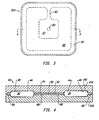
- Figure 3 is a top view of a heat spreader body portion 21A.
- the device of Figure 3 is used with a corresponding heat spreader bottom to form a heat spreader in accordance with the invention.
- both halves of the device are contoured, as opposed to the implementation of Figure 1 , where only one body portion of the device is contoured.
- Figure 4 illustrates a device 64 constructed with the heat spreader body portion 21A of Figure 3 .
- the device 64 includes a corresponding heat spreader bottom 21B.
- Figure 4 can be interpreted as a cross-sectional view taken along the line 4-4 of Figure 3 .
- Figure 4 also illustrates fluid 66 positioned within the evaporator 51 and the fluid path 50. Further, the figure illustrates the fluid 66 wicking into the fluid path 50. The figure illustrates that there is very little fluid on the walls of the adiabatic region 44, and a small amount of fluid on the walls of the condenser 46.
- Figure 4A is an exploded view of the device of Figure 4 .
- the figure illustrates the heat spreader top 21A and the heat spreader bottom 21B.
- the figure also illustrates that the fluid 66 fills the capillary fluid path 50.
- the shape of the fluid 66 is equivalent to the shape of the capillary fluid path 50.
- Figure 4A also illustrates a spacial region 67.
- the spacial region 67 conforms to the shape of the non-capillary region 32.
- the spacial region 67 can be thought of as the area where vapor exists. As shown in Figure 4 and as discussed below, in addition to vapor, some fluid does exist in the spacial region 67.
- Figure 5 is a top view of a heat spreader lid 68.
- the heat spreader lid 68 of Figure 5 includes an evaporator surface 57 with extended edge surface elements 72. Since vapor typically leaves the evaporator surface 57 at an edge, the configuration of Figure 5 provides an extended surface into the non-capillary region 32 to facilitate vapor entry.
- Figure 5 also illustrates a capillary fluid path 50 with extended edge surface elements 76.
- the extended edge surface elements 76 facilitate the capillary movement of fluid from the non-capillary region 32 to the fluid path 50.
- a tapered surface between the extended edge surface elements 76 and the condenser non-capillary region 32 is preferable to facilitate capillary fluid movement.
- all embodiments of the invention avoid abrupt surface transitions.
- Figure 6 illustrates an alternate heat spreader body 80 formed in accordance with the invention.
- the body 80 includes an evaporator plateau surface 57 connected to a fluid path bridge 63, which leads to a capillary fluid path 50.
- the capillary fluid path 50 includes extended surface elements in the form of peninsulas 84.
- the peninsulas 84 are larger than the extended surface elements 76 of Figure 5 , but they serve the same purpose of facilitating the capillary movement of fluid from the non-capillary region 32 to the capillary fluid path 50.
- Figure 7 is a cross-sectional view of the device 80 taken along the line 7-7 of Figure 6 .
- the capillary path 50 may be observed on either end of the figure.
- the peninsulas 84 may also be observed between non-capillary regions 32.
- the device of Figures 6 and 7 is a discrete component.
- the total vertical height of the device of Figure 7 is less than 3.0 mm, preferably approximately 2.0 mm.
- the vertical height of the non-capillary region 32 is consistent with the previously described embodiment.
- the vertical height associated with the path 50 is consistent with the previously described embodiment.
- Figure 8 is a top view of a dual heat source heat spreader body 90.
- the device 90 includes a first evaporator surface 57A and a second evaporator surface 57B.
- the first evaporator surface 57A is positioned over a first heat source, such as a semiconductor (not shown), while the second evaporator surface 57B is positioned over a second semiconductor (not shown).
- a first fluid path bridge 63 A attaches the first evaporator surface 57A to the planar capillary fluid path 50, while a second fluid path bridge 63B attaches the first evaporator surface 57A to the second evaporator surface 57B.
- a single non-capillary region 32 serves both evaporator regions defined by the evaporator surfaces 57A, 57B.
- the non-capillary region 32 has an open path between the two sides of the evaporator surfaces 57A, 57B.
- Figure 9 is a cross-sectional view taken along the line 9-9 of Figure 8.
- Figure 9 illustrates the planar capillary fluid path 50 at either end of the body 90.
- the figure also illustrates the first evaporator surface 57A positioned between non-capillary regions 32 and the second evaporator evaporator surface 57B positioned between non-capillary regions 32.
- Figure 10 illustrates a quad heat source heat spreader body 100.
- the body 100 is used in connection with a semiconductor package that houses four semiconductors.
- the body 100 includes a first evaporator surface 57A, a second evaporator surface 57B, a third evaporator surface 57C, and a fourth evaporator surface 57D.
- First, second, third, and fourth fluid path bridges 63A, 63B, 63C, and 63D are used to link the evaporator plateaus to the planar capillary fluid path 50.
- the non-capillary region 32 includes support pillars 102.
- the support pillars 102 operate as heat transfer pillars.
- the support aspect of the pillars 102 is important to prevent collapse of the non-capillary region 32 under vacuum conditions.
- Figure 11 is a cross-sectional view taken along the line 11-11 of Figure 10 .
- the figure illustrates the planar capillary fluid path 50, the evaporator surfaces 57C and 57D, the non-capillary region 32, and the support pillar 102.
- Figure 12 is another embodiment of a heat spreader body 110 formed in accordance with the invention.
- the heat spreader body 110 is positioned on a semiconductor package 111.
- a finned heat sink 114 is positioned on the body 110.
- the finned heat sink 114 includes a horizontal surface 116 supporting vertical fins 118.
- the heat spreader body 110 includes a sloping planar surface 112 extending from the evaporator 51 to the condenser 46 of the non-capillary region 32.
- the sloping planar surface 112 may be configured as a frustum of a cone. Liquid in the condenser 46 is drawn back to the evaporator 51 by the capillary action of the sloping planar surface 112. That is, capillary action draws fluid from the relatively large vertical clearance of the condenser 46 into the relatively small vertical clearance of the evaporator 51.
- this embodiment of the invention does not have a perimeter planar capillary fluid path.
- fluid is condensed in the non-capillary region 32 and is then drawn by capillarity into the evaporator 57, without the use of a fluid capillary path bridge.
- the advantage of this embodiment is that the fluid will be drawn into the evaporator 51 through multiple naturally-formed fluid capillary paths on surface 112.
- Figure 13 illustrates the heat spreader body 110 of Figure 12 in a vertical position with respect to gravity.
- the figure further illustrates the capillary action of a fluid within the body.
- Capillary action causes the fluid 120 to surround the heat transfer pillar 53.
- capillary action causes an upward extension of fluid 121 along the walls of the body 110, resulting in a concave fluid shape 122.
- Figure 13 illustrates the directional insensitivity of the device of the invention, this feature is an important benefit of the invention.
- Figure 14 is a cross-sectional view of still another heat spreader body 130 in accordance with the invention.
- the sloping planar surface 112 results in a large vertical clearance at the non-capillary region 32, which is proximately positioned to the evaporator 51.
- the large vertical clearance at the non-capillary region 32 results in a relatively low vapor pressure adjacent to the evaporator 51 to facilitate the vaporization of fluid in the evaporator 51.
- the sloping planar surface 112 extends to a planar capillary fluid path 50 at the perimeter of the body 130.
- the shape of the planar capillary fluid path 50 is shown in Figure 3 . However, unlike the embodiment of Figure 3 , in the embodiment of Figure 13 , a gentle slope exists between the path 50 and the non-capillary region 32.
- Figure 15 is a cross-sectional view of a heat spreader body 150 that integrally incorporates heat sink fins 152.
- the heat spreader body 150 is for use with a multi-chip semiconductor package 140, which houses a first semiconductor 28A and a second semiconductor 28B.
- the body 150 includes a first heat transfer pillar 53A surrounded by an evaporator 51 and a non-capillary region 32.
- the body includes a second heat transfer pillar 53B surrounded by an evaporator 51 and a non-capillary region 32.
- a sloping surface is used between the evaporator 51 and the non-capillary region 32, and thereby enjoys the previously described advantages.
- Figure 15 further illustrates a fan 154, including fan blades 156, positioned on top of the heat sink fins 152.
- the positioning of a fan 154 on or within heat sink fins 152 is known in the art.
- the present invention facilitates this practice by providing a low vertical profile mechanism to distribute heat from the center of a semiconductor package to the edge of a semiconductor package where the fan performs the most active cooling.
- Figure 16 illustrates the body 150 of Figure 15 in a vertical position.
- the figure also illustrates the fluid within the body 150.
- Capillary action within the void of the body 150 causes fluid to surround the two heat transfer pillars 53A and 53B.
- the capillary action toward the heat transfer pillars 53A and 53B will result in multiple natural capillary paths into the evaporator 51.
- Figure 17 illustrates a "radial" heat spreader embodiment of the invention.
- the term “radial” refers to the contour of the non-capillary region 32, which exists at the center of the device and extends from the center in sixteen different directions, in a radial pattern.
- the fluid capillary path 50 exists on the perimeter of the device and extends to the center of the device with sixteen different legs 162.
- the advantages of this embodiment are the numerous fluid capillary path 50 and non-capillary region 32 edges and the fact that vapor can easily migrate to practically any region of the radial non-capillary region 32. Similarly, there are many fluid capillary path legs back to the center of the device.
- Figure 18 is a cross-sectional view of the device of Figure 17 taken along the line 18-18.
- the figure shows the non-capillary region 32 at the center of the structure.
- the figure shows two fluid capillary paths 50 extending into the non-capillary region 32. Liquid evaporates at the end of these fluid capillary paths 50 and enters the non-capillary region 32. Then, in most cases, the vapor migrates out to the perimeter regions of the non-capillary region 32.
- Figure 18 also illustrates heat transfer pillars 53. As in previous embodiments, these pillars 53 also operate as support structures.
- Figure 19 is an enlarged view of the center region 164 shown in Figure 18 .
- Figure 19 illustrates the non-capillary region 32, the end of the fluid capillary paths 50, and the heat transfer pillars 53 positioned on the fluid capillary paths 50.
- Figure 20 is a side-view of a top body portion that is used for connection to the bottom body portion shown in Figure 16 .
- Figure 20 illustrates a recessed region for forming the non-capillary region 32.
- the figure illustrates the ceiling portion of the fluid capillary paths 50 and heat transfer pillars 53, which are mated with the heat transfer pillars 53 shown in Figure 18 .
- Figure 21 is a top view of the bottom body portion of a "circle array” heat spreader apparatus 170 in accordance with an embodiment of the invention.
- the non-capillary region 32 is in the form of a large number of discrete circular wells 164.
- the fluid capillary path 50 surrounds each of the non-capillary regions 164.
- Figure 21 also illustrates a large number of heat transfer pillars 53.
- This embodiment of the invention is advantageous because it allows fluid to easily migrate to almost any region of the structure.
- the embodiment provides a large number of edge surfaces for fluid to evaporate from the fluid capillary path 50 and to return to the fluid capillary path 50.
- the structure has a "universal" configuration that is effective with a single chip package, a dual chip package, or any other type of multi-chip module.
- Figure 22 is a side view taken along the line 22-22 of Figure 21 .
- the figure shows different non-capillary regions 164 surrounded by segments of the fluid capillary path 50.
- the figure also illustrates heat transfer pillars 53 positioned in the fluid capillary path 50.
- Figure 23 is an enlarged view of the region 172 of Figure 22 .
- Figure 23 illustrates a non-capillary region 164 surrounded by a fluid capillary path 50, which includes heat transfer pillars 53.
- Figure 24 is a top body portion 174 corresponding to the bottom body portion 170 of Figure 21 .
- the top body portion 174 is configured to mate with the bottom body portion 170.
- the top body portion 174 includes a fluid capillary path ceiling 50 with heat transfer pillars 53 for alignment with the same elements on the bottom body portion.
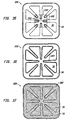
- Figure 25 is a top view of the bottom body portion of a "square matrix" heat spreader apparatus 180 in accordance with an embodiment of the invention.
- the fluid capillary path 50 is shaped like a grid and discrete square non-capillary regions 166 punctuate the grid.
- the embodiment also includes heat transfer pillars 53.
- Figure 26 is a side view of the apparatus 180 taken along the line 26-26 of Figure 25 .
- the figure illustrates the fluid capillary path 50 surrounding different non-capillary regions 166.
- Figure 27 is an enlarged view of the region 182 of Figure 26 .
- Figure 27 illustrates fluid capillary paths 50 surrounding a non-capillary region 166.
- the figure also illustrates a heat transfer pillar 53.
- a perimeter plateau 184 for connection with a lid is also illustrated.
- FIG 28 illustrates a lid 185 for attachment to the apparatus 180 of Figure 25 .
- the lid 185 includes a fluid capillary path lid portion 50 with heat transfer pillars 53, which mate with the heat transfer pillars 53 of Figure 25 .
- An advantage of the embodiment of the invention illustrated in Figures 25-28 is the ability of fluid to move in linear paths across the entire surface area of the device.
- the square configuration provides a relatively large amount of edge area for evaporated fluid to escape the fluid capillary path 50 and for condensed fluid to return to the fluid capillary path 50.
- the device of Figures 25-28 has a universal configuration that allows it to be effectively used with a variety of heat source distribution schemes.
- Figure 29 illustrates another heat spreader 200 in accordance with the invention.
- the heat spreader 200 includes non-capillary regions of varying size.
- the figure illustrates small patterned non-capillary regions 202, larger patterned non-capillary regions 204, and still larger patterned non-capillary regions 206.
- the patterned non-capillary regions are generally square in Figure 29 , but other patterns, such as circles or triangles may also be used.
- Figure 30 is a cross-sectional view taken along the line 30-30 of Figure 29 .
- the figure illustrates non-capillary regions 202-206 of varying sizes. Heat transfer pillars interrupt the different non-capillary regions so the different non-capillary regions are somewhat difficult to identify. This effect is more fully appreciated with reference to Figure 31 .
- Figure 31 is an enlarged view of the region 208 of Figure 30.
- Figure 31 illustrates that corresponding heat transfer pillars 53 from two sides of the body meet to form a continuous pillar structure.
- these pillars are useful as condensing surfaces. In other words, they are useful to form additional condensing area for vaporized fluid.
- a contoured surface in the non-capillary regions may also be used to provide additional condensing area for the vaporized fluid.
- Figure 32 is a cross-sectional view taken along the line 32-32 of Figure 29 .
- the figure illustrates non-capillary regions 202-206 of varying size. Note that in this figure the different non-capillary regions are not divided-up by heat transfer pillars 53.
- Figure 33 is an enlarged view of the region 210 of Figure 32.
- Figure 33 illustrates evaporator regions 51 formed between non-capillary regions 202. Observe once again that this figure is taken along a line that does not include heat transfer pillars 53.
- FIG 34 illustrates another heat spreader 220 in accordance with the invention.
- the heat spreader 220 includes a non-capillary region 32 surrounded by a capillary fluid path 50.
- the capillary fluid path 50 includes extended surface elements 222.
- the capillary fluid path 50 leads to a capillary fluid path bridge 223, which terminates in an evaporator plateau 224.
- the evaporator plateau 224 has a set of non-capillary regions 226.
- each non-capillary region 226 is in the form of a triangle.
- Figure 34 illustrates that different implementations of the disclosed invention may be combined to construct an optimal device for a particular application.
- Figure 35 is a plan view of another embodiment of the invention.
- the device 240 of Figure 35 generally corresponds to the device 160 of Figure 17 .
- the edges 244 of the capillary fluid path 50 in a heat generating region 242 are treated surfaces.
- a treated surface is a surface whose characteristics have been modified, for example, to include nucleation sites for the promotion of boiling, to include a coating for enhancing fluid wettability, to include a coating for surface passivation (rendering the wetted surface passive to oxidation or chemical attack from the fluid), or to include micro surface fissures for enhanced capillary flow.
- Micro surface fissures lessen the abrupt boundary between the capillary fluid path and the non-capillary region (the adiabatic and condenser regions). Micro fissures in the adiabatic surface near the evaporator region will cause fluid to migrate from the fluid capillary path to the micro fissures by the previously described capillary physics. This fluid will evaporate, thereby extending the evaporation (cooling) area. The micro fissures in the adiabatic surface near the condenser region aid in returning condensed fluid to the capillary fluid path. This results in a thinner liquid layer on the adiabatic surface, reducing the thermal resistance through the liquid layer.
- a nucleation surface is generally a roughened surface.
- the surface may be formed by sandblasting, laser etching or other technique that leaves a rough surface or a surface with small pockets in it.
- Figure 36 illustrates a device 250 with a treated surface along all of the capillary fluid path surfaces 50.
- the device 260 of Figure 37 illustrates that both the non-capillary region 32 and the entire fluid capillary path 50 may be formed with a treated surface 262.
- Figure 38 is a perspective view of another embodiment of the invention.
- the device 270 of Figure 38 has a pedestal 272 so that the remaining portion of the heat spreader 270 clears any objects adjacent to a heat generating surface.
- the semiconductor package 274 includes a set of on-board capacitors 276.
- the pedestal 272 is used to clear the on-board capacitors 276.
- the pedestal 272 is integrally formed with the remaining portion of the device 270.
- the pedestal 272 may be solid metal.
- FIG 39 is a perspective view of another embodiment of the invention.
- the heat spreader 280 is punctured with apertures 282.
- the apertures 282 allow protruding devices, such as on-board capacitors 276 of the semiconductor package 274, to extend through the heat spreader 280.
- FIG 40 is a perspective view of a heat spreader 290 formed in accordance with another embodiment of the invention.
- the heat spreader 290 is positioned on semiconductor package 292, which includes on-board capacitors 294.
- the heat spreader 290 extends from the surface of the semiconductor package 292 into a cooling region. For example, if the semiconductor package 292 is positioned in a lap top computer, then the heat spreader 290 may extend beyond the semiconductor package 292 underneath the keyboard of the lap top computer.
- the interior portion of the heat spreader 290 includes a capillary fluid path and non-capillary regions as described above.
- the heat spreader 290 also includes heat fins 296.
- the heat fins are not part of the interior portion of the heat spreader 290; that is, they do not have fluid circulating in them. Observe that the heat fins 296 are formed in the same plane as the heat spreader 290. This configuration is in contrast to prior art devices where the heat fins are orthogonal to the heat spreading surface.
- FIG 42 is a perspective view of a heat spreader 300 formed in accordance with another embodiment of the invention.
- the heat spreader 300 is positioned on a semiconductor package 292, which includes on-board capacitors 294.
- the heat spreader 300 includes a curved or bent region 302 which terminates in an orthogonal surface 304. Fluid circulates in capillary fluid path and non-capillary regions of the device 300. In particular, fluid continuously circulates from the horizontal region of the device 300, through the bend 302, and through the orthogonal surface 304.
- the device 300 also includes heat fins 306. Selected heat fins 306 include apertures 308, which may be used to attach a fan (not shown) to the orthogonal surface 304.
- planar capillary fluid path is a continuous surface. That is, it is continuous in the sense that the fluid can move over the entire surface. In other words, fluid can move from any region on the surface to any other region on the surface.
- substantially square refers to a length-to-width ratio of approximately 20:1, more preferably of approximately 2:1, and most preferably of approximately 1:1.
- Most prior art heat pipes and thermosiphons are configured as tubes.
- the invention is unique in that the capillary fluid movement is established by a planar capillary defined in two adjacent horizontal planes.
- capillary fluid movement is typically established through grooves formed in a surface.
- small vertical walls are formed in a horizontal surface to establish capillary fluid movement.
- Vertical surfaces are not used in the present invention to establish capillary fluid movement. Instead, capillary fluid movement is established by the top (ceiling) and bottom (floor) surfaces of the planar capillary path.
- the performance factor is normalized with respect to copper/tungsten. All heat spreaders measure 71.0 mm x 71.0 mm x 1.0 mm. All heat spreaders had a 19.0 mm x 19.0 mm square heat source centered on one side, and a 7.0 mm wide finned heat sink around the perimeter of the opposing side.
- the invention was implemented with molybdenum and included a non-capillary region with a depth of 1.0 mm and a capillary path with a depth of 0.125 mm. The device was charged with 0.329 cc of water. In general, the apparatus of the invention should be charged to an overfill condition of approximately 20%.
- the liquid that does not fit in the fluid capillary path when the fluid capillary path is filled should constitute approximately 20% of the total liquid within the device.
- the invention is implemented by using 0.007 cc of fluid per cm 2 of surface area of the device.
- the outstanding thermal conductivity characteristics of the apparatus of the invention allows the invention to be implemented in a variety of materials.
- the particular material used to implement the invention is not as crucial from a thermal conductivity standpoint. Instead, the material may be selected on the basis of cost, coefficient of thermal expansion, or other factors.
- One low cost implementation of the invention is in plastic, provided a hermetic seal is supplied.
- the fluid within the planar capillary fluid path moves very quickly during steady state operation.
- the fluid moves at a speed of between 25 and 200 mm/s. This speed is dramatically faster than any device that uses a wick. This characteristic of the invention is partly responsible for the outstanding thermal distribution performance.
Landscapes
- Engineering & Computer Science (AREA)
- Physics & Mathematics (AREA)
- Thermal Sciences (AREA)
- Mechanical Engineering (AREA)
- General Engineering & Computer Science (AREA)
- Life Sciences & Earth Sciences (AREA)
- Sustainable Development (AREA)
- Cooling Or The Like Of Semiconductors Or Solid State Devices (AREA)
- Cooling Or The Like Of Electrical Apparatus (AREA)
- Central Heating Systems (AREA)
Claims (25)
- Wärmeverteilungsvorrichtung (20), die aufweist:einen ersten flachen Körper (22) für eine Befestigung an einer wärmeerzeugenden Fläche, was zu einem heißen Bereich und einem kalten Bereich auf dem ersten flachen Körper (22) führt;einen zweiten flachen Körper (21), der mit dem ersten flachen Körper (22) verbunden ist, um einen Hohlraum zwischen dem ersten flachen Körper (22) und dem zweiten flachen Körper (21) zu definieren, wobei der Hohlraum einen flachen Kapillarweg (50) und einen nichtkapillaren Bereich (32) umfasst, wobei der flache Kapillarweg (50) eine untere flache Kapillarfläche (55) und eine entsprechende obere flache Kapillarfläche (57) umfasst, wobei die untere flache Kapillarfläche (55) mit Bezugnahme auf die obere flache Kapillarfläche (57) vertikal positioniert ist, um die Kapillarwirkung hervorzurufen; undein Fluid (66), das innerhalb des Hohlraumes für das Verteilen von Wärme positioniert ist, indem das Fluid (66) vom flachen Kapillarweg (50) im heißen Bereich verdampft wird, indem das Fluid (66) im nichtkapillaren Bereich (32) im kalten Bereich kondensiert wird, indem es vom nichtkapillaren Bereich (32) zum flachen Kapillarweg (50) im heißen Bereich durch eine Kapillarwirkung bewegt wird, und indem es zum heißen Bereich durch eine Kapillarwirkung bewegt wird.
- Vorrichtung (20) nach Anspruch 1, bei der der vertikale Abstand zwischen der unteren flachen Kapillarfläche (55) und der oberen flachen Kapillarfläche (57) weniger als 0,5 mm beträgt.
- Vorrichtung (20) nach Anspruch 2, bei der die untere flache Kapillarfläche (55) eine kontinuierliche Fläche und die obere flache Kapillarfläche (57) eine ausgerichtete kontinuierliche Fläche ist.
- Vorrichtung (20) nach Anspruch 1, bei der der erste flache Körper (22) und der zweite flache Körper (21) jeweils in einer im Wesentlichen quadratischen Konfiguration vorliegen.
- Vorrichtung (20) nach Anspruch 1, die außerdem eine Wärmeentzugsvorrichtung aufweist, die am zweiten flachen Körper (21) befestigt ist, wobei die Wärmeentzugsvorrichtung aus der Gruppe ausgewählt wird, die eine gerippte Wärmesenke (114) und einen Lüfter (154) umfasst.
- Vorrichtung (20) nach Anspruch 1, bei der der erste flache Körper (22) und der zweite flache Körper (21) eine kombinierte vertikale Höhe von weniger als 10 mm aufweisen.
- Vorrichtung (20) nach Anspruch 1, bei der der erste flache Körper (22) einen Boden des Hohlraumes und der zweite flache Körper (21) eine Decke des Hohlraumes bilden, wobei der vertikale Abstand zwischen der Decke und dem Boden im nichtkapillaren Bereich (32) kleiner ist als 9,0 mm.
- Vorrichtung (20) nach Anspruch 1, bei der die Menge des Fluids (66) innerhalb des Hohlraumes annähernd 0,010 Kubikzentimeter pro cm2 der Oberfläche der Vorrichtung (20) beträgt.
- Vorrichtung (20) nach Anspruch 1, bei der der nichtkapillare Bereich (32) ausgebildet ist, um einen mittleren Bereich mit Elementen einzuschließen, die sich von dort aus in einer radialen Konfiguration erstrecken.
- Vorrichtung (20) nach Anspruch 1, bei der der nichtkapillare Bereich (32) eine Vielzahl von nichtkapillaren Bereichen (164, 166) umfasst, die jeweils in einem vorgegebenen Muster geformt sind, das durch den flachen Kapillarweg (50) umgeben wird.
- Vorrichtung (20) nach Anspruch 10, bei der die Vielzahl der nichtkapillaren Bereiche (164, 166) veränderliche Größen aufweisen.
- Vorrichtung (20) nach Anspruch 10, bei der das vorgegebene Muster ein Quadrat (166) ist.
- Vorrichtung (20) nach Anspruch 10, bei der das vorgegebene Muster ein Kreis (164) ist.
- Vorrichtung (20) nach Anspruch 10, bei der das vorgegebene Muster ein Dreieck (226) ist.
- Vorrichtung (20) nach Anspruch 1, bei der der flache Kapillarweg (50) eine Umfangsfläche, eine Fluidwegbrücke (63) und ein Verdampferplatteau (60) umfasst.
- Vorrichtung (20) nach Anspruch 15, bei der das Verdampferplatteau (60) eine Vielzahl von nichtkapillaren Bereichen (226) umfasst, die jeweils in einem vorgegebenen Muster geformt sind.
- Vorrichtung (20) nach Anspruch 1, bei der der flache Kapillarweg (50) ausgestreckte Oberflächenelemente (72) umfasst.
- Vorrichtung (20) nach Anspruch 1, bei der die Oberflächen des Hohlraumes Kristallisationskeime (244) umfassen.
- Vorrichtung (20) nach Anspruch 18, bei der die Kristallisationskeime (244) nur auf dem Umfang des flachen Kapillarweges (50) positioniert sind.
- Vorrichtung (20) nach Anspruch 19, bei der die Kristallisationskeime (244) nur auf dem Umfang des flachen Kapillarweges (50) positioniert sind, was positionell der wärmeerzeugenden Fläche entspricht.
- Vorrichtung (20) nach Anspruch 1, bei der der erste flache Körper (22) ein Auflager (272) umfasst, um einen Abschnitt des ersten flachen Körpers (22) über die wärmeerzeugende Fläche anzuheben.
- Vorrichtung (20) nach Anspruch 1, bei der der erste flache Körper (22) und der zweite flache Körper (21) Öffnungen (282) umfassen, um Oberflächenvorsprünge auf der wärmeerzeugenden Fläche aufzunehmen.
- Vorrichtung (20) nach Anspruch 1, die außerdem Wärmeableitungsrippen (296) aufweist, die in der Ebene gebildet werden, die durch den ersten flachen Körper (22) und den zweiten flachen Körper (21) definiert wird.
- Vorrichtung (20) nach Anspruch 1, bei der der erste flache Körper (22) und der zweite flache Körper (21) einen gebogenen Bereich (302) umfassen.
- Vorrichtung (20) nach Anspruch 24, bei der der gebogene Bereich (302) bewirkt, dass der erste flache Körper (22) und der zweite flache Körper (21) in sowohl einer horizontalen Ebene als auch einer vertikalen Ebene vorhanden sind.
Applications Claiming Priority (3)
| Application Number | Priority Date | Filing Date | Title |
|---|---|---|---|
| US08/751,585 US6167948B1 (en) | 1996-11-18 | 1996-11-18 | Thin, planar heat spreader |
| US751585 | 1996-11-18 | ||
| PCT/US1997/020664 WO1998022767A1 (en) | 1996-11-18 | 1997-11-17 | Thin, planar heat spreader |
Publications (3)
| Publication Number | Publication Date |
|---|---|
| EP0938639A1 EP0938639A1 (de) | 1999-09-01 |
| EP0938639A4 EP0938639A4 (de) | 2000-03-01 |
| EP0938639B1 true EP0938639B1 (de) | 2012-09-26 |
Family
ID=25022668
Family Applications (1)
| Application Number | Title | Priority Date | Filing Date |
|---|---|---|---|
| EP97948260A Expired - Lifetime EP0938639B1 (de) | 1996-11-18 | 1997-11-17 | Flache dünne wärmesenke |
Country Status (8)
| Country | Link |
|---|---|
| US (2) | US6167948B1 (de) |
| EP (1) | EP0938639B1 (de) |
| JP (1) | JP4095674B2 (de) |
| KR (1) | KR100488055B1 (de) |
| CN (1) | CN1244914A (de) |
| AU (1) | AU5435798A (de) |
| CA (1) | CA2272260C (de) |
| WO (1) | WO1998022767A1 (de) |
Families Citing this family (195)
| Publication number | Priority date | Publication date | Assignee | Title |
|---|---|---|---|---|
| TW378267B (en) * | 1997-12-25 | 2000-01-01 | Furukawa Electric Co Ltd | Heat sink |
| FR2776764B1 (fr) * | 1998-03-30 | 2000-06-30 | Atmostat Etudes Et Rech | Dispositif d'echanges thermiques a fluide biphasique actif et procede de fabrication d'un tel dispositif |
| US6293332B2 (en) * | 1999-03-31 | 2001-09-25 | Jia Hao Li | Structure of a super-thin heat plate |
| US6896039B2 (en) * | 1999-05-12 | 2005-05-24 | Thermal Corp. | Integrated circuit heat pipe heat spreader with through mounting holes |
| KR100294317B1 (ko) * | 1999-06-04 | 2001-06-15 | 이정현 | 초소형 냉각 장치 |
| US6880624B1 (en) * | 1999-10-29 | 2005-04-19 | P1 Diamond, Inc. | Heat pipe |
| US7630198B2 (en) * | 2006-03-08 | 2009-12-08 | Cray Inc. | Multi-stage air movers for cooling computer systems and for other uses |
| EP1266548B2 (de) * | 2000-03-21 | 2015-07-29 | Liebert Corporation | Verfahren und gerät zur kühlung von elektronischen geräten |
| US6808015B2 (en) * | 2000-03-24 | 2004-10-26 | Denso Corporation | Boiling cooler for cooling heating element by heat transfer with boiling |
| US6382309B1 (en) * | 2000-05-16 | 2002-05-07 | Swales Aerospace | Loop heat pipe incorporating an evaporator having a wick that is liquid superheat tolerant and is resistant to back-conduction |
| US6474074B2 (en) * | 2000-11-30 | 2002-11-05 | International Business Machines Corporation | Apparatus for dense chip packaging using heat pipes and thermoelectric coolers |
| US6843308B1 (en) | 2000-12-01 | 2005-01-18 | Atmostat Etudes Et Recherches | Heat exchanger device using a two-phase active fluid, and a method of manufacturing such a device |
| US7556086B2 (en) * | 2001-04-06 | 2009-07-07 | University Of Maryland, College Park | Orientation-independent thermosyphon heat spreader |
| US6601643B2 (en) * | 2001-04-27 | 2003-08-05 | Samsung Electronics Co., Ltd | Flat evaporator |
| US6609560B2 (en) * | 2001-04-28 | 2003-08-26 | Samsung Electronics Co., Ltd. | Flat evaporator |
| US6778390B2 (en) | 2001-05-15 | 2004-08-17 | Nvidia Corporation | High-performance heat sink for printed circuit boards |
| US6667885B2 (en) * | 2001-07-20 | 2003-12-23 | Hewlett-Packard Development Company, L.P. | Attachment of a single heat dissipation device to multiple components with vibration isolation |
| US6607942B1 (en) | 2001-07-26 | 2003-08-19 | Taiwan Semiconductor Manufacturing Company | Method of fabricating as grooved heat spreader for stress reduction in an IC package |
| JP2003060371A (ja) * | 2001-08-16 | 2003-02-28 | Nec Corp | 通信機器筐体の放熱構造 |
| US6981543B2 (en) * | 2001-09-20 | 2006-01-03 | Intel Corporation | Modular capillary pumped loop cooling system |
| KR100438825B1 (ko) * | 2001-10-29 | 2004-07-05 | 삼성전자주식회사 | 단열 수단을 구비하는 열 전달 장치 |
| US6626233B1 (en) * | 2002-01-03 | 2003-09-30 | Thermal Corp. | Bi-level heat sink |
| US6848631B2 (en) | 2002-01-23 | 2005-02-01 | Robert James Monson | Flat fan device |
| US6606251B1 (en) | 2002-02-07 | 2003-08-12 | Cooligy Inc. | Power conditioning module |
| US6827134B1 (en) * | 2002-04-30 | 2004-12-07 | Sandia Corporation | Parallel-plate heat pipe apparatus having a shaped wick structure |
| US20040011509A1 (en) * | 2002-05-15 | 2004-01-22 | Wing Ming Siu | Vapor augmented heatsink with multi-wick structure |
| US6988534B2 (en) * | 2002-11-01 | 2006-01-24 | Cooligy, Inc. | Method and apparatus for flexible fluid delivery for cooling desired hot spots in a heat producing device |
| JP2004077051A (ja) * | 2002-08-20 | 2004-03-11 | Sony Corp | 熱輸送装置およびその製造方法 |
| US7044201B2 (en) * | 2002-08-21 | 2006-05-16 | Samsung Electronics Co., Ltd. | Flat heat transferring device and method of fabricating the same |
| US6880626B2 (en) * | 2002-08-28 | 2005-04-19 | Thermal Corp. | Vapor chamber with sintered grooved wick |
| AU2003270882A1 (en) | 2002-09-23 | 2004-05-04 | Cooligy, Inc. | Micro-fabricated electrokinetic pump with on-frit electrode |
| DE10246990A1 (de) * | 2002-10-02 | 2004-04-22 | Atotech Deutschland Gmbh | Mikrostrukturkühler und dessen Verwendung |
| TW540989U (en) * | 2002-10-04 | 2003-07-01 | Via Tech Inc | Thin planar heat distributor |
| US7173334B2 (en) * | 2002-10-11 | 2007-02-06 | Chien-Min Sung | Diamond composite heat spreader and associated methods |
| US20050189647A1 (en) * | 2002-10-11 | 2005-09-01 | Chien-Min Sung | Carbonaceous composite heat spreader and associated methods |
| WO2005038912A1 (en) | 2002-10-11 | 2005-04-28 | Chien-Min Sung | Carbonaceous heat spreader and associated methods |
| US20060113546A1 (en) * | 2002-10-11 | 2006-06-01 | Chien-Min Sung | Diamond composite heat spreaders having low thermal mismatch stress and associated methods |
| US6994151B2 (en) | 2002-10-22 | 2006-02-07 | Cooligy, Inc. | Vapor escape microchannel heat exchanger |
| US20040076408A1 (en) * | 2002-10-22 | 2004-04-22 | Cooligy Inc. | Method and apparatus for removeably coupling a heat rejection device with a heat producing device |
| US7156159B2 (en) | 2003-03-17 | 2007-01-02 | Cooligy, Inc. | Multi-level microchannel heat exchangers |
| JP2006522463A (ja) * | 2002-11-01 | 2006-09-28 | クーリギー インコーポレイテッド | 流体により冷却される超小型熱交換のための最適なスプレッダシステム、装置及び方法 |
| US6986382B2 (en) | 2002-11-01 | 2006-01-17 | Cooligy Inc. | Interwoven manifolds for pressure drop reduction in microchannel heat exchangers |
| US7836597B2 (en) | 2002-11-01 | 2010-11-23 | Cooligy Inc. | Method of fabricating high surface to volume ratio structures and their integration in microheat exchangers for liquid cooling system |
| JP2006516068A (ja) | 2002-11-01 | 2006-06-15 | クーリギー インコーポレイテッド | 発熱デバイスにおける温度均一性及びホットスポット冷却を実現する方法及び装置 |
| US7000684B2 (en) | 2002-11-01 | 2006-02-21 | Cooligy, Inc. | Method and apparatus for efficient vertical fluid delivery for cooling a heat producing device |
| CN100518672C (zh) * | 2002-11-08 | 2009-07-29 | 维特林克股份有限公司 | 经过蒂进入椎间盘的方法和装置 |
| JP4304576B2 (ja) * | 2002-12-12 | 2009-07-29 | ソニー株式会社 | 熱輸送装置及び電子機器 |
| US20040118553A1 (en) * | 2002-12-23 | 2004-06-24 | Graftech, Inc. | Flexible graphite thermal management devices |
| US20090044928A1 (en) * | 2003-01-31 | 2009-02-19 | Girish Upadhya | Method and apparatus for preventing cracking in a liquid cooling system |
| US7293423B2 (en) * | 2004-06-04 | 2007-11-13 | Cooligy Inc. | Method and apparatus for controlling freezing nucleation and propagation |
| US7090001B2 (en) | 2003-01-31 | 2006-08-15 | Cooligy, Inc. | Optimized multiple heat pipe blocks for electronics cooling |
| US7201012B2 (en) | 2003-01-31 | 2007-04-10 | Cooligy, Inc. | Remedies to prevent cracking in a liquid system |
| US6889755B2 (en) * | 2003-02-18 | 2005-05-10 | Thermal Corp. | Heat pipe having a wick structure containing phase change materials |
| US7017654B2 (en) | 2003-03-17 | 2006-03-28 | Cooligy, Inc. | Apparatus and method of forming channels in a heat-exchanging device |
| US6945317B2 (en) * | 2003-04-24 | 2005-09-20 | Thermal Corp. | Sintered grooved wick with particle web |
| US6906413B2 (en) * | 2003-05-30 | 2005-06-14 | Honeywell International Inc. | Integrated heat spreader lid |
| TW577683U (en) * | 2003-06-02 | 2004-02-21 | Jiun-Guang Luo | Heat sink |
| US20050022976A1 (en) * | 2003-06-26 | 2005-02-03 | Rosenfeld John H. | Heat transfer device and method of making same |
| WO2005006395A2 (en) * | 2003-06-26 | 2005-01-20 | Thermal Corp. | Heat transfer device and method of making same |
| US6820684B1 (en) | 2003-06-26 | 2004-11-23 | International Business Machines Corporation | Cooling system and cooled electronics assembly employing partially liquid filled thermal spreader |
| US6994152B2 (en) * | 2003-06-26 | 2006-02-07 | Thermal Corp. | Brazed wick for a heat transfer device |
| US6938680B2 (en) * | 2003-07-14 | 2005-09-06 | Thermal Corp. | Tower heat sink with sintered grooved wick |
| US7019971B2 (en) * | 2003-09-30 | 2006-03-28 | Intel Corporation | Thermal management systems for micro-components |
| JP3771233B2 (ja) * | 2003-10-08 | 2006-04-26 | 株式会社日立製作所 | 液冷ジャケット |
| US7025124B2 (en) * | 2003-10-24 | 2006-04-11 | Chin Wen Wang | Supporting structure for planar heat pipe |
| KR100633922B1 (ko) * | 2003-11-27 | 2006-10-16 | 엘에스전선 주식회사 | 판형 열전달 장치 |
| JP2007514121A (ja) | 2003-12-05 | 2007-05-31 | リーバート・コーポレイシヨン | 高密度熱負荷のための冷却システム |
| US20050126761A1 (en) * | 2003-12-10 | 2005-06-16 | Je-Young Chang | Heat pipe including enhanced nucleate boiling surface |
| TW200527185A (en) * | 2004-02-05 | 2005-08-16 | Wincomm Corp | Heat dissipating device |
| US20050207116A1 (en) * | 2004-03-22 | 2005-09-22 | Yatskov Alexander I | Systems and methods for inter-cooling computer cabinets |
| US6889756B1 (en) * | 2004-04-06 | 2005-05-10 | Epos Inc. | High efficiency isothermal heat sink |
| US7748440B2 (en) * | 2004-06-01 | 2010-07-06 | International Business Machines Corporation | Patterned structure for a thermal interface |
| US7616444B2 (en) | 2004-06-04 | 2009-11-10 | Cooligy Inc. | Gimballed attachment for multiple heat exchangers |
| US7188662B2 (en) | 2004-06-04 | 2007-03-13 | Cooligy, Inc. | Apparatus and method of efficient fluid delivery for cooling a heat producing device |
| US7330350B2 (en) * | 2004-06-04 | 2008-02-12 | Cray Inc. | Systems and methods for cooling computer modules in computer cabinets |
| WO2005125297A2 (en) * | 2004-06-14 | 2005-12-29 | Cray Inc. | Cooling electronic devices in computer systems |
| US6899165B1 (en) * | 2004-06-15 | 2005-05-31 | Hua Yin Electric Co., Ltd. | Structure of a heat-pipe cooler |
| TWI236870B (en) * | 2004-06-29 | 2005-07-21 | Ind Tech Res Inst | Heat dissipation apparatus with microstructure layer and manufacture method thereof |
| US7120027B2 (en) * | 2004-07-08 | 2006-10-10 | Cray Inc. | Assemblies for mounting electronic devices and associated heat sinks to computer modules and other structures |
| US7177156B2 (en) * | 2004-07-08 | 2007-02-13 | Cray Inc. | Assemblies for holding heat sinks and other structures in contact with electronic devices and other apparatuses |
| US7011145B2 (en) * | 2004-07-12 | 2006-03-14 | Industrial Technology Research Institute | Method for enhancing mobility of working fluid in liquid/gas phase heat dissipating device |
| US6957692B1 (en) * | 2004-08-31 | 2005-10-25 | Inventec Corporation | Heat-dissipating device |
| US7362571B2 (en) * | 2004-09-16 | 2008-04-22 | Cray Inc. | Inlet flow conditioners for computer cabinet air conditioning systems |
| CN101044811A (zh) * | 2004-11-14 | 2007-09-26 | 利伯特公司 | 用于立式板卡型计算机系统的机架中的集成式热交换器 |
| US20060196640A1 (en) * | 2004-12-01 | 2006-09-07 | Convergence Technologies Limited | Vapor chamber with boiling-enhanced multi-wick structure |
| US7193851B2 (en) * | 2004-12-09 | 2007-03-20 | Cray Inc. | Assemblies for holding heat sinks and other structures in contact with electronic devices and other apparatuses |
| US20060170094A1 (en) * | 2005-02-02 | 2006-08-03 | Intel Corporation | Semiconductor package integral heat spreader |
| US20080236795A1 (en) * | 2007-03-26 | 2008-10-02 | Seung Mun You | Low-profile heat-spreading liquid chamber using boiling |
| NL1028678C2 (nl) | 2005-04-01 | 2006-10-03 | Lemnis Lighting Ip Gmbh | Koellichaam, lamp en werkwijze voor het vervaardigen van een koellichaam. |
| CN101238766B (zh) * | 2005-08-04 | 2011-04-13 | 力博特公司 | 具有整体高性能的冷却系统和备用通风系统的电子设备机柜 |
| US8534348B2 (en) | 2005-09-01 | 2013-09-17 | Molex Incorporated | Heat pipe and method for manufacturing same |
| US7705342B2 (en) | 2005-09-16 | 2010-04-27 | University Of Cincinnati | Porous semiconductor-based evaporator having porous and non-porous regions, the porous regions having through-holes |
| TW200810676A (en) * | 2006-03-30 | 2008-02-16 | Cooligy Inc | Multi device cooling |
| JP4119944B2 (ja) * | 2006-04-03 | 2008-07-16 | 株式会社渕上ミクロ | ヒートパイプ |
| US7715194B2 (en) * | 2006-04-11 | 2010-05-11 | Cooligy Inc. | Methodology of cooling multiple heat sources in a personal computer through the use of multiple fluid-based heat exchanging loops coupled via modular bus-type heat exchangers |
| US20070256825A1 (en) * | 2006-05-04 | 2007-11-08 | Conway Bruce R | Methodology for the liquid cooling of heat generating components mounted on a daughter card/expansion card in a personal computer through the use of a remote drive bay heat exchanger with a flexible fluid interconnect |
| US20070277962A1 (en) * | 2006-06-01 | 2007-12-06 | Abb Research Ltd. | Two-phase cooling system for cooling power electronic components |
| US7411785B2 (en) * | 2006-06-05 | 2008-08-12 | Cray Inc. | Heat-spreading devices for cooling computer systems and associated methods of use |
| US20080006396A1 (en) * | 2006-06-30 | 2008-01-10 | Girish Upadhya | Multi-stage staggered radiator for high performance liquid cooling applications |
| US8042606B2 (en) * | 2006-08-09 | 2011-10-25 | Utah State University Research Foundation | Minimal-temperature-differential, omni-directional-reflux, heat exchanger |
| US8056615B2 (en) * | 2007-01-17 | 2011-11-15 | Hamilton Sundstrand Corporation | Evaporative compact high intensity cooler |
| TW200848683A (en) * | 2007-03-08 | 2008-12-16 | Convergence Technologies Ltd | Heat transfer device |
| TWM318115U (en) * | 2007-04-09 | 2007-09-01 | Tai Sol Electronics Co Ltd | Flat heat pipe |
| US8462508B2 (en) * | 2007-04-30 | 2013-06-11 | Hewlett-Packard Development Company, L.P. | Heat sink with surface-formed vapor chamber base |
| US8356410B2 (en) * | 2007-06-13 | 2013-01-22 | The Boeing Company | Heat pipe dissipating system and method |
| US7791188B2 (en) | 2007-06-18 | 2010-09-07 | Chien-Min Sung | Heat spreader having single layer of diamond particles and associated methods |
| CN101358699B (zh) * | 2007-08-01 | 2011-08-24 | 富士迈半导体精密工业(上海)有限公司 | 室外灯具 |
| TW200934352A (en) * | 2007-08-07 | 2009-08-01 | Cooligy Inc | Internal access mechanism for a server rack |
| US20090154091A1 (en) | 2007-12-17 | 2009-06-18 | Yatskov Alexander I | Cooling systems and heat exchangers for cooling computer components |
| US7942196B2 (en) * | 2007-12-27 | 2011-05-17 | Fu Zhun Precision Industry (Shen Zhen) Co., Ltd. | Heat spreader with vapor chamber |
| US8170724B2 (en) * | 2008-02-11 | 2012-05-01 | Cray Inc. | Systems and associated methods for controllably cooling computer components |
| US9297571B1 (en) | 2008-03-10 | 2016-03-29 | Liebert Corporation | Device and methodology for the removal of heat from an equipment rack by means of heat exchangers mounted to a door |
| US8250877B2 (en) * | 2008-03-10 | 2012-08-28 | Cooligy Inc. | Device and methodology for the removal of heat from an equipment rack by means of heat exchangers mounted to a door |
| US7898799B2 (en) * | 2008-04-01 | 2011-03-01 | Cray Inc. | Airflow management apparatus for computer cabinets and associated methods |
| EP2288430B9 (de) * | 2008-05-05 | 2016-06-22 | Cornell University | Verwendung einer Verbundmembran |
| US8254422B2 (en) * | 2008-08-05 | 2012-08-28 | Cooligy Inc. | Microheat exchanger for laser diode cooling |
| US8188595B2 (en) | 2008-08-13 | 2012-05-29 | Progressive Cooling Solutions, Inc. | Two-phase cooling for light-emitting devices |
| TWI459889B (zh) * | 2008-09-18 | 2014-11-01 | Pegatron Corp | 均溫板 |
| US20100085708A1 (en) * | 2008-10-07 | 2010-04-08 | Liebert Corporation | High-efficiency, fluid-cooled ups converter |
| US8081459B2 (en) * | 2008-10-17 | 2011-12-20 | Cray Inc. | Air conditioning systems for computer systems and associated methods |
| US7903403B2 (en) | 2008-10-17 | 2011-03-08 | Cray Inc. | Airflow intake systems and associated methods for use with computer cabinets |
| US9034277B2 (en) * | 2008-10-24 | 2015-05-19 | Honeywell International Inc. | Surface preparation for a microfluidic channel |
| KR101281043B1 (ko) * | 2008-11-10 | 2013-07-09 | 주식회사 만도 | 히트 싱크 |
| US9163883B2 (en) | 2009-03-06 | 2015-10-20 | Kevlin Thermal Technologies, Inc. | Flexible thermal ground plane and manufacturing the same |
| WO2010150064A1 (en) * | 2009-05-18 | 2010-12-29 | Huawei Technologies Co. Ltd. | Heat spreading device and method therefore |
| US9033030B2 (en) * | 2009-08-26 | 2015-05-19 | Munters Corporation | Apparatus and method for equalizing hot fluid exit plane plate temperatures in heat exchangers |
| US20110073292A1 (en) * | 2009-09-30 | 2011-03-31 | Madhav Datta | Fabrication of high surface area, high aspect ratio mini-channels and their application in liquid cooling systems |
| US10107560B2 (en) | 2010-01-14 | 2018-10-23 | University Of Virginia Patent Foundation | Multifunctional thermal management system and related method |
| US8213471B2 (en) * | 2010-01-22 | 2012-07-03 | Integral Laser Solutions, Llc | Thin disk laser operations with unique thermal management |
| US8472181B2 (en) | 2010-04-20 | 2013-06-25 | Cray Inc. | Computer cabinets having progressive air velocity cooling systems and associated methods of manufacture and use |
| US8077460B1 (en) | 2010-07-19 | 2011-12-13 | Toyota Motor Engineering & Manufacturing North America, Inc. | Heat exchanger fluid distribution manifolds and power electronics modules incorporating the same |
| TW201040485A (en) * | 2010-07-21 | 2010-11-16 | Asia Vital Components Co Ltd | Improved heat-dissipation structure |
| US8659896B2 (en) | 2010-09-13 | 2014-02-25 | Toyota Motor Engineering & Manufacturing North America, Inc. | Cooling apparatuses and power electronics modules |
| US8199505B2 (en) | 2010-09-13 | 2012-06-12 | Toyota Motor Engineering & Manufacturing Norh America, Inc. | Jet impingement heat exchanger apparatuses and power electronics modules |
| US9006086B2 (en) | 2010-09-21 | 2015-04-14 | Chien-Min Sung | Stress regulated semiconductor devices and associated methods |
| US8778784B2 (en) | 2010-09-21 | 2014-07-15 | Ritedia Corporation | Stress regulated semiconductor devices and associated methods |
| CN103221180A (zh) | 2010-09-21 | 2013-07-24 | 铼钻科技股份有限公司 | 具有基本平坦颗粒尖端的超研磨工具及其相关方法 |
| US20120080170A1 (en) * | 2010-10-04 | 2012-04-05 | Hsiu-Wei Yang | Plate-type heat pipe sealing structure and manufacturing method thereof |
| US9029991B2 (en) * | 2010-11-16 | 2015-05-12 | Conexant Systems, Inc. | Semiconductor packages with reduced solder voiding |
| US8427832B2 (en) | 2011-01-05 | 2013-04-23 | Toyota Motor Engineering & Manufacturing North America, Inc. | Cold plate assemblies and power electronics modules |
| US8391008B2 (en) | 2011-02-17 | 2013-03-05 | Toyota Motor Engineering & Manufacturing North America, Inc. | Power electronics modules and power electronics module assemblies |
| US8482919B2 (en) | 2011-04-11 | 2013-07-09 | Toyota Motor Engineering & Manufacturing North America, Inc. | Power electronics card assemblies, power electronics modules, and power electronics devices |
| US20120267077A1 (en) * | 2011-04-21 | 2012-10-25 | Toyota Motor Engineering & Manufacturing North America, Inc. | Cooling apparatuses and power electronics modules comprising the same |
| US9149896B1 (en) | 2011-05-11 | 2015-10-06 | Thermal Management Technologies | Thermal control, truss-plate apparatus and method |
| AU2012232968B2 (en) * | 2011-10-31 | 2014-11-13 | Abb Technology Ag | Thermosiphon cooler arrangement in modules with electric and/or electronic components |
| US10449323B2 (en) | 2012-03-30 | 2019-10-22 | Fisher & Paykel Healthcare Limited | Humidification system |
| US8893513B2 (en) | 2012-05-07 | 2014-11-25 | Phononic Device, Inc. | Thermoelectric heat exchanger component including protective heat spreading lid and optimal thermal interface resistance |
| US20130291555A1 (en) | 2012-05-07 | 2013-11-07 | Phononic Devices, Inc. | Thermoelectric refrigeration system control scheme for high efficiency performance |
| US8933860B2 (en) | 2012-06-12 | 2015-01-13 | Integral Laser Solutions, Inc. | Active cooling of high speed seeker missile domes and radomes |
| GB2568409B (en) | 2012-06-25 | 2019-07-31 | Fisher & Paykel Healthcare Ltd | Patient interface with microstructures |
| US8643173B1 (en) | 2013-01-04 | 2014-02-04 | Toyota Motor Engineering & Manufacturing North America, Inc. | Cooling apparatuses and power electronics modules with single-phase and two-phase surface enhancement features |
| US9066460B2 (en) | 2013-01-17 | 2015-06-23 | International Business Machines Corporation | Disassemblable electronic assembly with leak-inhibiting coolant capillaries |
| EP4223346B1 (de) | 2013-03-14 | 2025-01-01 | Fisher & Paykel Healthcare Limited | Befeuchtungskammer |
| KR101519717B1 (ko) * | 2013-08-06 | 2015-05-12 | 현대자동차주식회사 | 전자 제어 유닛용 방열 장치 |
| US9131631B2 (en) | 2013-08-08 | 2015-09-08 | Toyota Motor Engineering & Manufacturing North America, Inc. | Jet impingement cooling apparatuses having enhanced heat transfer assemblies |
| JP6121854B2 (ja) * | 2013-09-18 | 2017-04-26 | 東芝ホームテクノ株式会社 | シート型ヒートパイプまたは携帯情報端末 |
| JP6121893B2 (ja) * | 2013-12-24 | 2017-04-26 | 東芝ホームテクノ株式会社 | シート型ヒートパイプ |
| US9593871B2 (en) | 2014-07-21 | 2017-03-14 | Phononic Devices, Inc. | Systems and methods for operating a thermoelectric module to increase efficiency |
| US10458683B2 (en) | 2014-07-21 | 2019-10-29 | Phononic, Inc. | Systems and methods for mitigating heat rejection limitations of a thermoelectric module |
| KR101686709B1 (ko) | 2014-08-19 | 2016-12-14 | 김상준 | 표면 미세 요철을 갖는 극박 히트 파이프 및 이의 제조 방법 |
| US12523431B2 (en) | 2014-09-15 | 2026-01-13 | Kelvin Thermal Technologies, Inc. | Polymer-based microfabricated thermal ground plane |
| EP3194157A4 (de) * | 2014-09-15 | 2018-04-25 | The Regents of The University of Colorado, A Body Corporate | Vakuumunterstützter wärmeverteiler |
| US11598594B2 (en) | 2014-09-17 | 2023-03-07 | The Regents Of The University Of Colorado | Micropillar-enabled thermal ground plane |
| WO2016044638A1 (en) * | 2014-09-17 | 2016-03-24 | The Regents Of The University Of Colorado, A Body Corporate | Micropillar-enabled thermal ground plane |
| US11988453B2 (en) | 2014-09-17 | 2024-05-21 | Kelvin Thermal Technologies, Inc. | Thermal management planes |
| US12385697B2 (en) | 2014-09-17 | 2025-08-12 | Kelvin Thermal Technologies, Inc. | Micropillar-enabled thermal ground plane |
| US20180320984A1 (en) | 2017-05-08 | 2018-11-08 | Kelvin Thermal Technologies, Inc. | Thermal management planes |
| US11397057B2 (en) * | 2014-09-26 | 2022-07-26 | Asia Vital Components Co., Ltd. | Vapor chamber structure |
| JP6101728B2 (ja) * | 2015-03-30 | 2017-03-22 | 株式会社フジクラ | ベーパーチャンバー |
| US20170020026A1 (en) * | 2015-07-14 | 2017-01-19 | Celsia Technologies Taiwan, Inc. | Vapor chamber structure |
| US20170122673A1 (en) * | 2015-11-02 | 2017-05-04 | Acmecools Tech. Ltd. | Micro heat pipe and method of manufacturing micro heat pipe |
| US10302367B2 (en) * | 2015-12-04 | 2019-05-28 | Intel Corporation | Non-metallic vapor chambers |
| US11543188B2 (en) * | 2016-06-15 | 2023-01-03 | Delta Electronics, Inc. | Temperature plate device |
| US11306974B2 (en) * | 2016-06-15 | 2022-04-19 | Delta Electronics, Inc. | Temperature plate and heat dissipation device |
| US10619941B2 (en) * | 2016-09-29 | 2020-04-14 | Delta Electronics, Inc. | Heat pipe structure |
| US12104856B2 (en) * | 2016-10-19 | 2024-10-01 | Kelvin Thermal Technologies, Inc. | Method and device for optimization of vapor transport in a thermal ground plane using void space in mobile systems |
| CN110192273B (zh) | 2016-11-08 | 2023-07-28 | 开尔文热技术股份有限公司 | 用于在热接地平面中散布高热通量的方法和设备 |
| KR20160146614A (ko) | 2016-12-08 | 2016-12-21 | 김상준 | 극박 박막형 히트 파이프 |
| CN106767062B (zh) * | 2016-12-27 | 2020-06-05 | 山东飞龙制冷设备有限公司 | 纳米表面铜基脉动热管 |
| CN106679473B (zh) * | 2016-12-27 | 2020-06-12 | 山东飞龙制冷设备有限公司 | 双层多通道平板纳米表面脉动热管及其制备方法 |
| JP6905678B2 (ja) * | 2017-03-27 | 2021-07-21 | 大日本印刷株式会社 | ベーパーチャンバ、ベーパーチャンバ搭載基板およびベーパーチャンバ用金属シート |
| US10203169B2 (en) * | 2017-06-12 | 2019-02-12 | Microsoft Technology Licensing, Llc | Thermal management devices, systems and methods |
| US11065671B2 (en) * | 2017-06-22 | 2021-07-20 | Asia Vital Components Co., Ltd. | Method of manufacturing a heat dissipation device |
| JP2019032134A (ja) * | 2017-08-09 | 2019-02-28 | レノボ・シンガポール・プライベート・リミテッド | プレート型熱輸送装置及び電子機器 |
| CN108761969B (zh) * | 2018-04-27 | 2021-04-16 | 重庆恩光科技有限公司 | 全密封式监控器 |
| US20190353431A1 (en) * | 2018-05-18 | 2019-11-21 | Microsoft Technology Licensing, Llc | Two-phase thermodynamic system having compensational wick geometry to enhance fluid flow |
| US10935325B2 (en) | 2018-09-28 | 2021-03-02 | Microsoft Technology Licensing, Llc | Two-phase thermodynamic system having a porous microstructure sheet with varying surface energy to optimize utilization of a working fluid |
| US10962298B2 (en) | 2018-09-28 | 2021-03-30 | Microsoft Technology Licensing, Llc | Two-phase thermodynamic system having a porous microstructure sheet to increase an aggregate thin-film evaporation area of a working fluid |
| WO2020123631A1 (en) | 2018-12-11 | 2020-06-18 | Kelvin Thermal Technologies, Inc. | Vapor chamber |
| US11495519B2 (en) | 2019-06-07 | 2022-11-08 | Dana Canada Corporation | Apparatus for thermal management of electronic components |
| WO2021041853A1 (en) | 2019-08-28 | 2021-03-04 | Aavid Thermalloy, Llc | Method and apparatus for forming liquid filled heat transfer device |
| DE112020004077T5 (de) | 2019-08-28 | 2022-05-19 | Aavid Thermalloy, Llc. | Verfahren und Einrichtung zum Bilden von flüssigkeitsgefüllter Wärmetransfer-Vorrichtung |
| WO2021258028A1 (en) | 2020-06-19 | 2021-12-23 | Kelvin Thermal Technologies, Inc. | Folding thermal ground plane |
| US12262508B2 (en) * | 2020-12-18 | 2025-03-25 | Intel Corporation | Heat pipe for improved thermal performance at cold plate interface |
| TWI872435B (zh) * | 2023-01-12 | 2025-02-11 | 薩摩亞商塔普林克科技有限公司 | 整合式均熱板 |
Family Cites Families (174)
| Publication number | Priority date | Publication date | Assignee | Title |
|---|---|---|---|---|
| US3680189A (en) | 1970-12-09 | 1972-08-01 | Noren Products Inc | Method of forming a heat pipe |
| US3700028A (en) | 1970-12-10 | 1972-10-24 | Noren Products Inc | Heat pipes |
| US3714981A (en) | 1971-02-03 | 1973-02-06 | Noren Prod Inc | Heat shield assembly |
| US4440215A (en) | 1971-02-08 | 1984-04-03 | Q-Dot Corporation | Heat pipe |
| US4107922A (en) | 1972-09-04 | 1978-08-22 | Robert Bosch Gmbh | Equipment for exhaust gas detoxification in internal combustion engines |
| DE2243428A1 (de) | 1972-09-04 | 1974-03-14 | Bosch Gmbh Robert | Anlage zur abgasentgiftung von brennkraftmaschinen |
| US4020898A (en) | 1973-02-14 | 1977-05-03 | Q-Dot Corporation | Heat pipe and method and apparatus for fabricating same |
| US3906604A (en) * | 1974-02-01 | 1975-09-23 | Hitachi Cable | Method of forming heat transmissive wall surface |
| DE2427968C3 (de) | 1974-06-10 | 1980-03-27 | Hermann J. 8000 Muenchen Schladitz | Wärmerohr |
| US4019098A (en) | 1974-11-25 | 1977-04-19 | Sundstrand Corporation | Heat pipe cooling system for electronic devices |
| US3997381A (en) | 1975-01-10 | 1976-12-14 | Intel Corporation | Method of manufacture of an epitaxial semiconductor layer on an insulating substrate |
| GB1484831A (en) | 1975-03-17 | 1977-09-08 | Hughes Aircraft Co | Heat pipe thermal mounting plate for cooling circuit card-mounted electronic components |
| GB1525709A (en) | 1975-04-10 | 1978-09-20 | Chloride Silent Power Ltd | Thermo-electric generators |
| US4046190A (en) * | 1975-05-22 | 1977-09-06 | The United States Of America As Represented By The Administrator Of The National Aeronautics And Space Administration | Flat-plate heat pipe |
| US4050507A (en) | 1975-06-27 | 1977-09-27 | International Business Machines Corporation | Method for customizing nucleate boiling heat transfer from electronic units immersed in dielectric coolant |
| US4004441A (en) | 1975-08-28 | 1977-01-25 | Grumman Aerospace Corporation | Process for modifying capillary grooves |
| US4026348A (en) | 1975-10-06 | 1977-05-31 | Bell Telephone Laboratories, Incorporated | Heat pipe switch |
| US4067315A (en) | 1975-10-24 | 1978-01-10 | Corning Glass Works | Solar heat pipe |
| US4058159A (en) | 1975-11-10 | 1977-11-15 | Hughes Aircraft Company | Heat pipe with capillary groove and floating artery |
| US4057963A (en) | 1976-03-11 | 1977-11-15 | Hughes Aircraft Company | Heat pipe capable of operating against gravity and structures utilizing same |
| US4047198A (en) * | 1976-04-19 | 1977-09-06 | Hughes Aircraft Company | Transistor cooling by heat pipes having a wick of dielectric powder |
| US4082575A (en) | 1976-04-21 | 1978-04-04 | Thermacore, Inc. | Production of liquid compatible metals |
| US4196504A (en) | 1977-04-06 | 1980-04-08 | Thermacore, Inc. | Tunnel wick heat pipes |
| US4186796A (en) | 1977-05-17 | 1980-02-05 | Usui International Industry, Ltd. | Heat pipe element |
| US4099556A (en) | 1977-05-23 | 1978-07-11 | Roberts Jr Charles C | Variable thermal conductance reflux heat pipe |
| GB1605405A (en) | 1977-07-22 | 1995-07-19 | Rolls Royce | Heat pipes |
| US4312012A (en) | 1977-11-25 | 1982-01-19 | International Business Machines Corp. | Nucleate boiling surface for increasing the heat transfer from a silicon device to a liquid coolant |
| US4381818A (en) | 1977-12-19 | 1983-05-03 | International Business Machines Corporation | Porous film heat transfer |
| US4257356A (en) | 1978-06-22 | 1981-03-24 | Electric Power Research Institute | Heat exchanging apparatus and method |
| US4203129A (en) | 1978-07-11 | 1980-05-13 | International Business Machines Corporation | Bubble generating tunnels for cooling semiconductor devices |
| US4230173A (en) | 1978-09-05 | 1980-10-28 | Thermacore, Inc. | Closely coupled two phase heat exchanger |
| DE2841051A1 (de) | 1978-09-21 | 1980-04-03 | Daimler Benz Ag | Waermeuebertragung nach dem prinzip des waermerohres |
| US4274479A (en) | 1978-09-21 | 1981-06-23 | Thermacore, Inc. | Sintered grooved wicks |
| US4194559A (en) | 1978-11-01 | 1980-03-25 | Thermacore, Inc. | Freeze accommodating heat pipe |
| US4288897A (en) | 1978-12-04 | 1981-09-15 | Uop Inc. | Method of producing a nucleate boiling surface on a heat transfer member |
| US4219078A (en) | 1978-12-04 | 1980-08-26 | Uop Inc. | Heat transfer surface for nucleate boiling |
| US4212347A (en) | 1978-12-20 | 1980-07-15 | Thermacore, Inc. | Unfurlable heat pipe |
| FR2454064A1 (fr) | 1979-04-13 | 1980-11-07 | Commissariat Energie Atomique | Capteur solaire, du genre caloduc, protege contre les surpressions |
| US4220195A (en) | 1979-05-24 | 1980-09-02 | The United States Of America As Represented By The Secretary Of The Navy | Ion drag pumped heat pipe |
| US4322737A (en) | 1979-11-20 | 1982-03-30 | Intel Corporation | Integrated circuit micropackaging |
| US4248295A (en) | 1980-01-17 | 1981-02-03 | Thermacore, Inc. | Freezable heat pipe |
| SE8003579L (sv) * | 1980-05-13 | 1981-11-14 | Ericsson Telefon Ab L M | Kylanordning for diskreta eller pa kretskort monterade elektroniska komponenter |
| US4351388A (en) | 1980-06-13 | 1982-09-28 | Mcdonnell Douglas Corporation | Inverted meniscus heat pipe |
| EP0053452B1 (de) | 1980-12-02 | 1984-03-14 | Marston Palmer Ltd. | Wärmetauscher |
| US4352392A (en) | 1980-12-24 | 1982-10-05 | Thermacore, Inc. | Mechanically assisted evaporator surface |
| US4345642A (en) | 1980-12-24 | 1982-08-24 | Thermacore, Inc. | Articulated heat pipes |
| US4485670A (en) | 1981-02-13 | 1984-12-04 | The United States Of America As Represented By The Administrator Of The National Aeronautics And Space Administration | Heat pipe cooled probe |
| US4372377A (en) | 1981-03-16 | 1983-02-08 | The United States Of America As Represented By The Administrator Of The National Aeronautics And Space Administration | Heat pipes containing alkali metal working fluid |
| US4386505A (en) * | 1981-05-01 | 1983-06-07 | The Board Of Trustees Of The Leland Stanford Junior University | Refrigerators |
| US4438807A (en) | 1981-07-02 | 1984-03-27 | Carrier Corporation | High performance heat transfer tube |
| US4474170A (en) | 1981-08-06 | 1984-10-02 | The United States Of America As Represented By The United States Department Of Energy | Glass heat pipe evacuated tube solar collector |
| US4470450A (en) | 1981-10-22 | 1984-09-11 | Lockheed Missiles & Space Co. | Pump-assisted heat pipe |
| US4492266A (en) | 1981-10-22 | 1985-01-08 | Lockheed Missiles & Space Company, Inc. | Manifolded evaporator for pump-assisted heat pipe |
| US4516631A (en) | 1981-11-04 | 1985-05-14 | Combustion Engineering, Inc. | Nozzle cooled by heat pipe means |
| US4441548A (en) | 1981-12-28 | 1984-04-10 | The Boeing Company | High heat transport capacity heat pipe |
| US4489777A (en) | 1982-01-21 | 1984-12-25 | Del Bagno Anthony C | Heat pipe having multiple integral wick structures |
| DE3203369C1 (de) * | 1982-02-02 | 1983-10-13 | Daimler-Benz Ag, 7000 Stuttgart | Flächenheizkörper für Fahrzeuge |
| US4685512A (en) | 1982-03-22 | 1987-08-11 | Grumman Aerospace Corporation | Capillary-pumped heat transfer panel and system |
| SU1270507A1 (ru) | 1982-03-23 | 1986-11-15 | Отдел физико-технических проблем энергетики Уральского научного центра АН СССР | Испарительна камера тепловой трубы |
| US4413671A (en) | 1982-05-03 | 1983-11-08 | Hughes Aircraft Company | Switchable on-off heat pipe |
| US4545427A (en) | 1982-05-24 | 1985-10-08 | Grumman Aerospace Corporation | Re-entrant groove heat pipe |
| US4457059A (en) | 1982-05-24 | 1984-07-03 | Grumman Aerospace Corporation | Method of making a re-entrant groove heat pipe |
| US4523636A (en) | 1982-09-20 | 1985-06-18 | Stirling Thermal Motors, Inc. | Heat pipe |
| US4632179A (en) | 1982-09-20 | 1986-12-30 | Stirling Thermal Motors, Inc. | Heat pipe |
| US4565243A (en) | 1982-11-24 | 1986-01-21 | Thermacore, Inc. | Hybrid heat pipe |
| US4478275A (en) | 1983-07-25 | 1984-10-23 | Thermacore, Inc. | Abrasion resistant heat pipe |
| US4602314A (en) | 1983-10-14 | 1986-07-22 | Intel Corporation | Heat conduction mechanism for semiconductor devices |
| US4617093A (en) | 1984-02-08 | 1986-10-14 | University Of Cincinnati | Method and apparatus for separating components of a mixture |
| GB2160306B (en) | 1984-06-14 | 1987-12-09 | Total Energy Conservation And | Method of geothermal energy recovery |
| US4520865A (en) | 1984-06-25 | 1985-06-04 | Lockheed Missiles & Space Company, Inc. | Gas-tolerant arterial heat pipe |
| US5002122A (en) | 1984-09-25 | 1991-03-26 | Thermacore, Inc. | Tunnel artery wick for high power density surfaces |
| US4712609A (en) | 1984-11-21 | 1987-12-15 | Iversen Arthur H | Heat sink structure |
| US4671348A (en) | 1985-05-21 | 1987-06-09 | Mcdonnell Douglas Corporation | Transverse flow edge heat pipe |
| US4898231A (en) | 1985-09-30 | 1990-02-06 | Kabushiki Kaisha Toshiba | Heat-pipe system and method of and apparatus for controlling a flow rate of a working fluid in a liquid pipe of the heat pipe system |
| US4693124A (en) | 1986-02-25 | 1987-09-15 | Micromeritics Instrument Co. | Temperature controlling apparatus for use with pore volume and surface area analyzers |
| USRE33567E (en) | 1986-02-25 | 1991-04-09 | Micromeritics Instrument Corporation | Temperature controlling apparatus for use with pore volume and surface area analyzers |
| US4697205A (en) | 1986-03-13 | 1987-09-29 | Thermacore, Inc. | Heat pipe |
| US4681995A (en) | 1986-04-04 | 1987-07-21 | Ahern Brian S | Heat pipe ring stacked assembly |
| US4683940A (en) | 1986-07-16 | 1987-08-04 | Thermacore, Inc. | Unidirectional heat pipe |
| US4696010A (en) | 1986-07-16 | 1987-09-22 | Thermacore, Inc. | Thermally stabilized laser cavity |
| JPH07112030B2 (ja) * | 1986-11-04 | 1995-11-29 | 株式会社フジクラ | マイクロヒ−トパイプの製造方法 |
| US4794984A (en) | 1986-11-10 | 1989-01-03 | Lin Pang Yien | Arrangement for increasing heat transfer coefficient between a heating surface and a boiling liquid |
| US4765396A (en) | 1986-12-16 | 1988-08-23 | The United States Of America As Represented By The Administrator Of The National Aeronautics And Space Administration | Polymeric heat pipe wick |
| US4706740A (en) | 1987-03-11 | 1987-11-17 | The United States Of America As Represented By The Secretary Of The Air Force | Ventable survivable heat pipe vapor chamber spacecraft radiator |
| US4810929A (en) | 1987-03-30 | 1989-03-07 | Strumbos William P | Spark plug temperature control |
| US4789026A (en) | 1987-06-26 | 1988-12-06 | Thermacore, Inc. | Polished surface capillary grooves |
| US4789023A (en) | 1987-07-28 | 1988-12-06 | Grant Frederic F | Vibration isolating heat sink |
| US4854379A (en) | 1987-09-25 | 1989-08-08 | Thermacore, Inc. | Vapor resistant arteries |
| US4815528A (en) | 1987-09-25 | 1989-03-28 | Thermacore, Inc. | Vapor resistant arteries |
| US4799537A (en) | 1987-10-13 | 1989-01-24 | Thermacore, Inc. | Self regulating heat pipe |
| US4899810A (en) | 1987-10-22 | 1990-02-13 | General Electric Company | Low pressure drop condenser/heat pipe heat exchanger |
| US4785875A (en) | 1987-11-12 | 1988-11-22 | Stirling Thermal Motors, Inc. | Heat pipe working liquid distribution system |
| US4824496A (en) | 1987-12-24 | 1989-04-25 | Intel Corporation | Method and apparatus for removing reticle guides |
| US4807697A (en) | 1988-02-18 | 1989-02-28 | Thermacore, Inc. | External artery heat pipe |
| US5185073A (en) | 1988-06-21 | 1993-02-09 | International Business Machines Corporation | Method of fabricating nendritic materials |
| US5137461A (en) | 1988-06-21 | 1992-08-11 | International Business Machines Corporation | Separable electrical connection technology |
| US4884627A (en) | 1988-06-27 | 1989-12-05 | Amir Abtahi | Omni-directional heat pipe |
| US4989070A (en) | 1988-11-10 | 1991-01-29 | Coriolis Corporation | Modular heat sink structure |
| US4857421A (en) | 1988-11-14 | 1989-08-15 | Thermacore, Inc. | Alkali metal thermoelectric genreator |
| US4917173A (en) | 1988-11-15 | 1990-04-17 | The United States Of America As Represented By The National Aeronautics And Space Administration | Monogroove liquid heat exchanger |
| US5351397A (en) | 1988-12-12 | 1994-10-04 | Olin Corporation | Method of forming a nucleate boiling surface by a roll forming |
| US4884169A (en) | 1989-01-23 | 1989-11-28 | Technology Enterprises Company | Bubble generation in condensation wells for cooling high density integrated circuit chips |
| US4883116A (en) | 1989-01-31 | 1989-11-28 | The United States Of America As Represented By The Administrator Of The National Aeronautics And Space Administration | Ceramic heat pipe wick |
| US4880052A (en) | 1989-02-27 | 1989-11-14 | Thermacore, Inc. | Heat pipe cooling plate |
| US4880053A (en) * | 1989-04-24 | 1989-11-14 | The Board Of Governors Of Wayne State University | Two-phase cooling apparatus for electronic equipment and the like |
| US4941527A (en) | 1989-04-26 | 1990-07-17 | Thermacore, Inc. | Heat pipe with temperature gradient |
| US5283464A (en) | 1989-06-08 | 1994-02-01 | The Furukawa Electric Co., Ltd. | Electrically insulated heat pipe type cooling apparatus for semiconductor |
| US5366598A (en) * | 1989-06-30 | 1994-11-22 | Eltech Systems Corporation | Method of using a metal substrate of improved surface morphology |
| US5262040A (en) * | 1989-06-30 | 1993-11-16 | Eltech Systems Corporation | Method of using a metal substrate of improved surface morphology |
| US5167788A (en) * | 1989-06-30 | 1992-12-01 | Eltech Systems Corporation | Metal substrate of improved surface morphology |
| US5297621A (en) | 1989-07-13 | 1994-03-29 | American Electronic Analysis | Method and apparatus for maintaining electrically operating device temperatures |
| US5051146A (en) | 1989-08-03 | 1991-09-24 | Lockheed Missiles & Space Company, Inc. | Apparatus for fabricating a graded-groove heat pipe |
| JP2741255B2 (ja) | 1989-08-18 | 1998-04-15 | 株式会社日立製作所 | 沸騰冷却用伝熱体 |
| US4972812A (en) | 1989-08-30 | 1990-11-27 | Strumbos William P | Spark plug thermal control |
| US4917177A (en) | 1989-09-21 | 1990-04-17 | Thermacore, Inc. | Cooled artery extension |
| US5036905A (en) | 1989-10-26 | 1991-08-06 | The United States Of America As Represented By The Secretary Of The Air Force | High efficiency heat exchanger |
| US5018573A (en) | 1989-12-18 | 1991-05-28 | Carrier Corporation | Method for manufacturing a high efficiency heat transfer surface and the surface so manufactured |
| JP3065347B2 (ja) | 1990-02-20 | 2000-07-17 | ザ、プロクター、エンド、ギャンブル、カンパニー | 開放型毛管チャンネル構造、前記毛管チャンネルの製造法およびこの方法に使用される押出ダイス |
| US5242644A (en) | 1990-02-20 | 1993-09-07 | The Procter & Gamble Company | Process for making capillary channel structures and extrusion die for use therein |
| US5231756A (en) | 1990-05-18 | 1993-08-03 | Shinko Electric Industries Co., Ltd. | Process for manufacturing a multi-layer lead frame |
| CA2053055C (en) | 1990-10-11 | 1997-02-25 | Tsukasa Mizuno | Liquid cooling system for lsi packages |
| US5298685A (en) | 1990-10-30 | 1994-03-29 | International Business Machines Corporation | Interconnection method and structure for organic circuit boards |
| US5076352A (en) | 1991-02-08 | 1991-12-31 | Thermacore, Inc. | High permeability heat pipe wick structure |
| US5195575A (en) | 1991-04-09 | 1993-03-23 | Roger Wylie | Passive three-phase heat tube for the protection of apparatus from exceeding maximum or minimum safe working temperatures |
| US5398748A (en) | 1991-06-05 | 1995-03-21 | Fujitsu Limited | Heat pipe connector and electronic apparatus and radiating fins having such connector |
| FR2679382B1 (fr) | 1991-07-15 | 1996-12-13 | Accumulateurs Fixes | Generateur electrochimique de forte energie massique specifique. |
| US5127471A (en) | 1991-07-26 | 1992-07-07 | Weislogel Mark M | Pulse thermal energy transport/storage system |
| JPH05118780A (ja) | 1991-08-09 | 1993-05-14 | Mitsubishi Electric Corp | ヒートパイプ |
| US5355942A (en) * | 1991-08-26 | 1994-10-18 | Sun Microsystems, Inc. | Cooling multi-chip modules using embedded heat pipes |
| US5168926A (en) | 1991-09-25 | 1992-12-08 | Intel Corporation | Heat sink design integrating interface material |
| US5209288A (en) | 1991-10-10 | 1993-05-11 | Grumman Aerospace Corporation | Interrupted monogroove slot |
| US5386143A (en) | 1991-10-25 | 1995-01-31 | Digital Equipment Corporation | High performance substrate, electronic package and integrated circuit cooling process |
| US5199165A (en) | 1991-12-13 | 1993-04-06 | Hewlett-Packard Company | Heat pipe-electrical interconnect integration method for chip modules |
| US5168921A (en) | 1991-12-23 | 1992-12-08 | Thermacore, Inc. | Cooling plate with internal expandable heat pipe |
| US5349823A (en) | 1992-02-14 | 1994-09-27 | Intel Corporation | Integrated refrigerated computer module |
| US5289337A (en) | 1992-02-21 | 1994-02-22 | Intel Corporation | Heatspreader for cavity down multi-chip module with flip chip |
| JPH0629683A (ja) | 1992-03-31 | 1994-02-04 | Furukawa Electric Co Ltd:The | 電子機器用ヒートパイプ式放熱ユニット |
| US5273635A (en) | 1992-06-04 | 1993-12-28 | Thermacore, Inc. | Electrolytic heater |
| US5219516A (en) | 1992-06-16 | 1993-06-15 | Thermacore, Inc. | Thermionic generator module with heat pipes |
| DE4222340C2 (de) | 1992-07-08 | 1996-07-04 | Daimler Benz Aerospace Ag | Wärmerohr |
| US5283715A (en) * | 1992-09-29 | 1994-02-01 | International Business Machines, Inc. | Integrated heat pipe and circuit board structure |
| US5404938A (en) | 1992-11-17 | 1995-04-11 | Heat Pipe Technology, Inc. | Single assembly heat transfer device |
| US5375041A (en) | 1992-12-02 | 1994-12-20 | Intel Corporation | Ra-tab array bump tab tape based I.C. package |
| US5267611A (en) | 1993-01-08 | 1993-12-07 | Thermacore, Inc. | Single phase porous layer heat exchanger |
| US5329996A (en) | 1993-01-08 | 1994-07-19 | Thermacore, Inc. | Porous layer heat exchanger |
| US5339214A (en) | 1993-02-12 | 1994-08-16 | Intel Corporation | Multiple-fan microprocessor cooling through a finned heat pipe |
| US5394936A (en) | 1993-03-12 | 1995-03-07 | Intel Corporation | High efficiency heat removal system for electric devices and the like |
| US5427174A (en) | 1993-04-30 | 1995-06-27 | Heat Transfer Devices, Inc. | Method and apparatus for a self contained heat exchanger |
| US5412535A (en) | 1993-08-24 | 1995-05-02 | Convex Computer Corporation | Apparatus and method for cooling electronic devices |
| US5388958A (en) | 1993-09-07 | 1995-02-14 | Heat Pipe Technology, Inc. | Bladeless impeller and impeller having internal heat transfer mechanism |
| US5485671A (en) * | 1993-09-10 | 1996-01-23 | Aavid Laboratories, Inc. | Method of making a two-phase thermal bag component cooler |
| US5397746A (en) | 1993-11-03 | 1995-03-14 | Intel Corporation | Quad flat package heat slug composition |
| US5415225A (en) | 1993-12-15 | 1995-05-16 | Olin Corporation | Heat exchange tube with embossed enhancement |
| US5556811A (en) | 1993-12-21 | 1996-09-17 | Intel Corporation | Method of optimizing operating parameters of an integrated circuit package having a voltage regulator mounted thereon |
| US5444909A (en) | 1993-12-29 | 1995-08-29 | Intel Corporation | Method of making a drop-in heat sink |
| US5489805A (en) | 1993-12-29 | 1996-02-06 | Intel Corporation | Slotted thermal dissipater for a semiconductor package |
| US5506756A (en) | 1994-01-25 | 1996-04-09 | Intel Corporation | Tape BGA package die-up/die down |
| US5444602A (en) | 1994-02-25 | 1995-08-22 | Intel Corporation | An electronic package that has a die coupled to a lead frame by a dielectric tape and a heat sink that providees both an electrical and a thermal path between the die and teh lead frame |
| US5442910A (en) | 1994-03-21 | 1995-08-22 | Thermacore, Inc. | Reaction motor structure and method of construction |
| US5552960A (en) | 1994-04-14 | 1996-09-03 | Intel Corporation | Collapsible cooling apparatus for portable computer |
| US5475565A (en) | 1994-06-03 | 1995-12-12 | Intel Corporation | Power distribution lid for IC package |
| US5544696A (en) | 1994-07-01 | 1996-08-13 | The United States Of America As Represented By The Secretary Of The Air Force | Enhanced nucleate boiling heat transfer for electronic cooling and thermal energy transfer |
| US5492570A (en) | 1994-07-05 | 1996-02-20 | Thermacore, Inc. | Hybrid thermal electric generator |
| US5560423A (en) | 1994-07-28 | 1996-10-01 | Aavid Laboratories, Inc. | Flexible heat pipe for integrated circuit cooling apparatus |
| US5497938A (en) | 1994-09-01 | 1996-03-12 | Intel Corporation | Tape with solder forms and methods for transferring solder to chip assemblies |
| US5513070A (en) | 1994-12-16 | 1996-04-30 | Intel Corporation | Dissipation of heat through keyboard using a heat pipe |
| JP3438087B2 (ja) * | 1995-02-16 | 2003-08-18 | アクトロニクス株式会社 | リボン状プレートヒートパイプ |
| US5557502A (en) | 1995-03-02 | 1996-09-17 | Intel Corporation | Structure of a thermally and electrically enhanced plastic ball grid array package |
| US5568360A (en) | 1995-03-29 | 1996-10-22 | Dell Usa, L.P. | Heat pipe device and method for attaching same to a computer keyboard |
| US5549155A (en) | 1995-04-18 | 1996-08-27 | Thermacore, Inc. | Integrated circuit cooling apparatus |
| US5535094A (en) | 1995-04-26 | 1996-07-09 | Intel Corporation | Integrated circuit package with an integral heat sink and fan |
| US5507092A (en) | 1995-06-06 | 1996-04-16 | Hisateru Akachi | L-type heat sink |
| US5725049A (en) * | 1995-10-31 | 1998-03-10 | The United States Of America As Represented By The Administrator Of The National Aeronautics And Space Administration | Capillary pumped loop body heat exchanger |
| US5769154A (en) * | 1996-01-29 | 1998-06-23 | Sandia Corporation | Heat pipe with embedded wick structure |
-
1996
- 1996-11-18 US US08/751,585 patent/US6167948B1/en not_active Expired - Lifetime
-
1997
- 1997-11-17 CA CA002272260A patent/CA2272260C/en not_active Expired - Fee Related
- 1997-11-17 EP EP97948260A patent/EP0938639B1/de not_active Expired - Lifetime
- 1997-11-17 AU AU54357/98A patent/AU5435798A/en not_active Abandoned
- 1997-11-17 JP JP52372898A patent/JP4095674B2/ja not_active Expired - Fee Related
- 1997-11-17 WO PCT/US1997/020664 patent/WO1998022767A1/en not_active Ceased
- 1997-11-17 KR KR10-1999-7004367A patent/KR100488055B1/ko not_active Expired - Fee Related
- 1997-11-17 CN CN97181438A patent/CN1244914A/zh active Pending
- 1997-12-18 US US08/992,889 patent/US6158502A/en not_active Expired - Lifetime
Also Published As
| Publication number | Publication date |
|---|---|
| JP4095674B2 (ja) | 2008-06-04 |
| KR100488055B1 (ko) | 2005-05-09 |
| KR20000053344A (ko) | 2000-08-25 |
| JP2001505644A (ja) | 2001-04-24 |
| CA2272260C (en) | 2007-09-18 |
| CN1244914A (zh) | 2000-02-16 |
| WO1998022767A1 (en) | 1998-05-28 |
| EP0938639A4 (de) | 2000-03-01 |
| AU5435798A (en) | 1998-06-10 |
| CA2272260A1 (en) | 1998-05-28 |
| EP0938639A1 (de) | 1999-09-01 |
| US6158502A (en) | 2000-12-12 |
| US6167948B1 (en) | 2001-01-02 |
Similar Documents
| Publication | Publication Date | Title |
|---|---|---|
| EP0938639B1 (de) | Flache dünne wärmesenke | |
| US5864466A (en) | Thermosyphon-powered jet-impingement cooling device | |
| US7237337B2 (en) | Heat dissipating apparatus having micro-structure layer and method of fabricating the same | |
| US6550531B1 (en) | Vapor chamber active heat sink | |
| US6064572A (en) | Thermosyphon-powered jet-impingement cooling device | |
| US7005738B2 (en) | Semiconductor package with lid heat spreader | |
| US6263959B1 (en) | Plate type heat pipe and cooling structure using it | |
| US6698511B2 (en) | Vortex heatsink for high performance thermal applications | |
| US6631077B2 (en) | Heat spreader with oscillating flow | |
| US20100018678A1 (en) | Vapor Chamber with Boiling-Enhanced Multi-Wick Structure | |
| US6437437B1 (en) | Semiconductor package with internal heat spreader | |
| US20130020053A1 (en) | Low-profile heat-spreading liquid chamber using boiling | |
| US6749013B2 (en) | Heat sink | |
| US20060005950A1 (en) | Structure of heat conductive plate | |
| JPH088421B2 (ja) | 放熱装置 | |
| JP2002231868A (ja) | 高密度チップ実装用装置 | |
| JPH05243441A (ja) | 放熱装置 | |
| JP2014143417A (ja) | 一体化した薄膜蒸発式熱拡散器および平面ヒートパイプヒートシンク | |
| JP3403307B2 (ja) | ヒートスプレッダとそれを用いた冷却器 | |
| JPS6367760A (ja) | マイクロヒ−トパイプ内蔵の放熱フイン構造 |
Legal Events
| Date | Code | Title | Description |
|---|---|---|---|
| PUAI | Public reference made under article 153(3) epc to a published international application that has entered the european phase |
Free format text: ORIGINAL CODE: 0009012 |
|
| 17P | Request for examination filed |
Effective date: 19990519 |
|
| AK | Designated contracting states |
Kind code of ref document: A1 Designated state(s): AT BE CH DE DK ES FI FR GB GR IE IT LI LU MC NL PT SE |
|
| A4 | Supplementary search report drawn up and despatched |
Effective date: 20000119 |
|
| AK | Designated contracting states |
Kind code of ref document: A4 Designated state(s): AT BE CH DE DK ES FI FR GB GR IE IT LI LU MC NL PT SE |
|
| RIC1 | Information provided on ipc code assigned before grant |
Free format text: 7F 28D 15/00 A, 7H 05K 7/20 B, 7H 01L 23/24 B, 7H 01L 23/427 B |
|
| 17Q | First examination report despatched |
Effective date: 20030903 |
|
| GRAP | Despatch of communication of intention to grant a patent |
Free format text: ORIGINAL CODE: EPIDOSNIGR1 |
|
| GRAS | Grant fee paid |
Free format text: ORIGINAL CODE: EPIDOSNIGR3 |
|
| GRAA | (expected) grant |
Free format text: ORIGINAL CODE: 0009210 |
|
| AK | Designated contracting states |
Kind code of ref document: B1 Designated state(s): AT BE CH DE DK ES FI FR GB GR IE IT LI LU MC NL PT SE |
|
| REG | Reference to a national code |
Ref country code: GB Ref legal event code: FG4D |
|
| REG | Reference to a national code |
Ref country code: CH Ref legal event code: EP |
|
| REG | Reference to a national code |
Ref country code: AT Ref legal event code: REF Ref document number: 577257 Country of ref document: AT Kind code of ref document: T Effective date: 20121015 |
|
| REG | Reference to a national code |
Ref country code: IE Ref legal event code: FG4D |
|
| REG | Reference to a national code |
Ref country code: DE Ref legal event code: R096 Ref document number: 69740484 Country of ref document: DE Effective date: 20121122 |
|
| PG25 | Lapsed in a contracting state [announced via postgrant information from national office to epo] |
Ref country code: FI Free format text: LAPSE BECAUSE OF FAILURE TO SUBMIT A TRANSLATION OF THE DESCRIPTION OR TO PAY THE FEE WITHIN THE PRESCRIBED TIME-LIMIT Effective date: 20120926 |
|
| PGFP | Annual fee paid to national office [announced via postgrant information from national office to epo] |
Ref country code: FR Payment date: 20121114 Year of fee payment: 16 Ref country code: DE Payment date: 20121015 Year of fee payment: 16 |
|
| REG | Reference to a national code |
Ref country code: AT Ref legal event code: MK05 Ref document number: 577257 Country of ref document: AT Kind code of ref document: T Effective date: 20120926 |
|
| REG | Reference to a national code |
Ref country code: NL Ref legal event code: VDEP Effective date: 20120926 |
|
| PG25 | Lapsed in a contracting state [announced via postgrant information from national office to epo] |
Ref country code: SE Free format text: LAPSE BECAUSE OF FAILURE TO SUBMIT A TRANSLATION OF THE DESCRIPTION OR TO PAY THE FEE WITHIN THE PRESCRIBED TIME-LIMIT Effective date: 20120926 |
|
| PGFP | Annual fee paid to national office [announced via postgrant information from national office to epo] |
Ref country code: GB Payment date: 20121004 Year of fee payment: 16 |
|
| PG25 | Lapsed in a contracting state [announced via postgrant information from national office to epo] |
Ref country code: NL Free format text: LAPSE BECAUSE OF FAILURE TO SUBMIT A TRANSLATION OF THE DESCRIPTION OR TO PAY THE FEE WITHIN THE PRESCRIBED TIME-LIMIT Effective date: 20120926 Ref country code: ES Free format text: LAPSE BECAUSE OF FAILURE TO SUBMIT A TRANSLATION OF THE DESCRIPTION OR TO PAY THE FEE WITHIN THE PRESCRIBED TIME-LIMIT Effective date: 20130106 Ref country code: BE Free format text: LAPSE BECAUSE OF FAILURE TO SUBMIT A TRANSLATION OF THE DESCRIPTION OR TO PAY THE FEE WITHIN THE PRESCRIBED TIME-LIMIT Effective date: 20120926 |
|
| PG25 | Lapsed in a contracting state [announced via postgrant information from national office to epo] |
Ref country code: PT Free format text: LAPSE BECAUSE OF FAILURE TO SUBMIT A TRANSLATION OF THE DESCRIPTION OR TO PAY THE FEE WITHIN THE PRESCRIBED TIME-LIMIT Effective date: 20130128 |
|
| PG25 | Lapsed in a contracting state [announced via postgrant information from national office to epo] |
Ref country code: AT Free format text: LAPSE BECAUSE OF FAILURE TO SUBMIT A TRANSLATION OF THE DESCRIPTION OR TO PAY THE FEE WITHIN THE PRESCRIBED TIME-LIMIT Effective date: 20120926 |
|
| REG | Reference to a national code |
Ref country code: CH Ref legal event code: PL |
|
| PG25 | Lapsed in a contracting state [announced via postgrant information from national office to epo] |
Ref country code: DK Free format text: LAPSE BECAUSE OF FAILURE TO SUBMIT A TRANSLATION OF THE DESCRIPTION OR TO PAY THE FEE WITHIN THE PRESCRIBED TIME-LIMIT Effective date: 20120926 Ref country code: LI Free format text: LAPSE BECAUSE OF NON-PAYMENT OF DUE FEES Effective date: 20121130 Ref country code: CH Free format text: LAPSE BECAUSE OF NON-PAYMENT OF DUE FEES Effective date: 20121130 |
|
| PLBE | No opposition filed within time limit |
Free format text: ORIGINAL CODE: 0009261 |
|
| STAA | Information on the status of an ep patent application or granted ep patent |
Free format text: STATUS: NO OPPOSITION FILED WITHIN TIME LIMIT |
|
| REG | Reference to a national code |
Ref country code: IE Ref legal event code: MM4A |
|
| PG25 | Lapsed in a contracting state [announced via postgrant information from national office to epo] |
Ref country code: IT Free format text: LAPSE BECAUSE OF FAILURE TO SUBMIT A TRANSLATION OF THE DESCRIPTION OR TO PAY THE FEE WITHIN THE PRESCRIBED TIME-LIMIT Effective date: 20120926 |
|
| 26N | No opposition filed |
Effective date: 20130627 |
|
| REG | Reference to a national code |
Ref country code: DE Ref legal event code: R097 Ref document number: 69740484 Country of ref document: DE Effective date: 20130627 |
|
| PG25 | Lapsed in a contracting state [announced via postgrant information from national office to epo] |
Ref country code: IE Free format text: LAPSE BECAUSE OF NON-PAYMENT OF DUE FEES Effective date: 20121117 |
|
| PG25 | Lapsed in a contracting state [announced via postgrant information from national office to epo] |
Ref country code: MC Free format text: LAPSE BECAUSE OF NON-PAYMENT OF DUE FEES Effective date: 20121130 |
|
| PG25 | Lapsed in a contracting state [announced via postgrant information from national office to epo] |
Ref country code: LU Free format text: LAPSE BECAUSE OF NON-PAYMENT OF DUE FEES Effective date: 20121117 |
|
| GBPC | Gb: european patent ceased through non-payment of renewal fee |
Effective date: 20131117 |
|
| REG | Reference to a national code |
Ref country code: FR Ref legal event code: ST Effective date: 20140731 |
|
| REG | Reference to a national code |
Ref country code: DE Ref legal event code: R119 Ref document number: 69740484 Country of ref document: DE Effective date: 20140603 |
|
| PG25 | Lapsed in a contracting state [announced via postgrant information from national office to epo] |
Ref country code: DE Free format text: LAPSE BECAUSE OF NON-PAYMENT OF DUE FEES Effective date: 20140603 Ref country code: GR Free format text: LAPSE BECAUSE OF FAILURE TO SUBMIT A TRANSLATION OF THE DESCRIPTION OR TO PAY THE FEE WITHIN THE PRESCRIBED TIME-LIMIT Effective date: 20120926 |
|
| PG25 | Lapsed in a contracting state [announced via postgrant information from national office to epo] |
Ref country code: GB Free format text: LAPSE BECAUSE OF NON-PAYMENT OF DUE FEES Effective date: 20131117 Ref country code: FR Free format text: LAPSE BECAUSE OF NON-PAYMENT OF DUE FEES Effective date: 20131202 |