EP0933263B1 - Aufblasbare Sicherheitsgurtvorrichtung - Google Patents
Aufblasbare Sicherheitsgurtvorrichtung Download PDFInfo
- Publication number
- EP0933263B1 EP0933263B1 EP98122932A EP98122932A EP0933263B1 EP 0933263 B1 EP0933263 B1 EP 0933263B1 EP 98122932 A EP98122932 A EP 98122932A EP 98122932 A EP98122932 A EP 98122932A EP 0933263 B1 EP0933263 B1 EP 0933263B1
- Authority
- EP
- European Patent Office
- Prior art keywords
- belt
- cover
- inflatable
- envelope
- knit cover
- Prior art date
- Legal status (The legal status is an assumption and is not a legal conclusion. Google has not performed a legal analysis and makes no representation as to the accuracy of the status listed.)
- Expired - Lifetime
Links
Images


Classifications
-
- B—PERFORMING OPERATIONS; TRANSPORTING
- B60—VEHICLES IN GENERAL
- B60R—VEHICLES, VEHICLE FITTINGS, OR VEHICLE PARTS, NOT OTHERWISE PROVIDED FOR
- B60R21/00—Arrangements or fittings on vehicles for protecting or preventing injuries to occupants or pedestrians in case of accidents or other traffic risks
- B60R21/02—Occupant safety arrangements or fittings, e.g. crash pads
- B60R21/16—Inflatable occupant restraints or confinements designed to inflate upon impact or impending impact, e.g. air bags
- B60R21/20—Arrangements for storing inflatable members in their non-use or deflated condition; Arrangement or mounting of air bag modules or components
- B60R21/201—Packaging straps or envelopes for inflatable members
-
- B—PERFORMING OPERATIONS; TRANSPORTING
- B60—VEHICLES IN GENERAL
- B60R—VEHICLES, VEHICLE FITTINGS, OR VEHICLE PARTS, NOT OTHERWISE PROVIDED FOR
- B60R21/00—Arrangements or fittings on vehicles for protecting or preventing injuries to occupants or pedestrians in case of accidents or other traffic risks
- B60R21/02—Occupant safety arrangements or fittings, e.g. crash pads
- B60R21/16—Inflatable occupant restraints or confinements designed to inflate upon impact or impending impact, e.g. air bags
- B60R21/18—Inflatable occupant restraints or confinements designed to inflate upon impact or impending impact, e.g. air bags the inflatable member formed as a belt or harness or combined with a belt or harness arrangement
-
- D—TEXTILES; PAPER
- D04—BRAIDING; LACE-MAKING; KNITTING; TRIMMINGS; NON-WOVEN FABRICS
- D04B—KNITTING
- D04B21/00—Warp knitting processes for the production of fabrics or articles not dependent on the use of particular machines; Fabrics or articles defined by such processes
- D04B21/14—Fabrics characterised by the incorporation by knitting, in one or more thread, fleece, or fabric layers, of reinforcing, binding, or decorative threads; Fabrics incorporating small auxiliary elements, e.g. for decorative purposes
- D04B21/16—Fabrics characterised by the incorporation by knitting, in one or more thread, fleece, or fabric layers, of reinforcing, binding, or decorative threads; Fabrics incorporating small auxiliary elements, e.g. for decorative purposes incorporating synthetic threads
-
- D—TEXTILES; PAPER
- D10—INDEXING SCHEME ASSOCIATED WITH SUBLASSES OF SECTION D, RELATING TO TEXTILES
- D10B—INDEXING SCHEME ASSOCIATED WITH SUBLASSES OF SECTION D, RELATING TO TEXTILES
- D10B2403/00—Details of fabric structure established in the fabric forming process
- D10B2403/03—Shape features
- D10B2403/031—Narrow fabric of constant width
- D10B2403/0312—Bulk fabric, e.g. belts
-
- D—TEXTILES; PAPER
- D10—INDEXING SCHEME ASSOCIATED WITH SUBLASSES OF SECTION D, RELATING TO TEXTILES
- D10B—INDEXING SCHEME ASSOCIATED WITH SUBLASSES OF SECTION D, RELATING TO TEXTILES
- D10B2505/00—Industrial
- D10B2505/12—Vehicles
- D10B2505/122—Safety belts
Definitions
- the present invention relates to an inflatable belt used in a seat belt device for protecting a vehicle occupant at a vehicle collision, and more particularly to an inflatable belt comprising an envelope-like belt, which is inflated with gas from a gas generator.
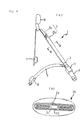
- Fig 9(a) is a perspective view of an inflatable belt device of the publication and Fig. 9(b) is a sectional view taken along line B-B of Fig. 9(a).
- the inflatable belt device 1 comprises a shoulder belt 2 to be extended at an angle from the right side to the left side of an occupant, a lap belt 3 to be extended from the right side to the left side of the occupant, a buckle 4 fixed to, for example, a vehicle floor, a tongue 5 to be inserted into and engaged with the buckle 4 when the occupant wears the seat belt, and an intermediate guide 6 for guiding the shoulder belt 2.
- the shoulder belt 2 comprises a normal belt 2a which is the same as a typical conventional seat belt, and an inflatable belt 2b connected to an end of the normal belt 2a.
- the normal belt 2a is slidably hung by the intermediate guide 6.
- the other end of the normal belt 2a is connected to a seat belt retractor 7 with an emergency locking mechanism (ELR) which is fixed to the vehicle body.
- ELR emergency locking mechanism
- the normal belt 2a is arranged in such a manner as to be wound into the seat belt retractor 7.
- the inflatable belt 2b is positioned to be in contact with the occupant and is connected to the tongue 5 at an end opposite to the end connected to the normal belt 2a.
- the lap belt 3 comprises a normal belt which is the same as a typical conventional seat belt, of which one end is connected to the tongue 5 and the other end is connected to a seat belt retractor 8 with an emergency locking mechanism (ELR) which is fixed to the vehicle body.
- ELR emergency locking mechanism
- the tongue 5 and the buckle 4 are provided with paths for introducing gas from the gas generator 9 to the inflatable belt 2b.
- the inflatable belt 2b comprises an belt body 2c formed in an envelop shape and a cover 2d.
- the belt body 2c is folded as shown by solid lines in Fig. 9(b) and covered by the cover 2d.
- the both ends of the cover 2d are then connected by stitching 2e so that the inflatable belt 2b is normally kept in a band-like shape.
- the stitching 2e of the cover 2d is easily torn by expansion force of the shoulder belt 2 when the gas generator 9 is actuated so that the inflatable belt 2b is developed as shown by a two-dot chain line.
- Fig. 17 of Japanese Patent Unexamined Publication No. H6-56001, Fig. 3 of USP 3,801,156, and Fig. 2 of USP 3,841,654 disclose that an inflatable belt in which portions overlapped with each other in its folded state are connected by a fastener, a snap fastener, or stitching so that the folded member is kept in a flat band-like shape.
- EP-A-0 652 140 discloses an automobile safety air belt with air bag according to the preamble of claim 1.
- the air bag is normally folded several times and is covered with a protection cover made of a fabric material.
- This protection cover is partially breakable at a section corresponding to the air bag, which is bonded to the protection cover at its rear surface only such that it is prevented from separation from the protection cover when it is charged with the pressurized air to be expanded.
- pressurized air is supplied to the air bag, the folded air bag is expanded and breaks the breakable section in order to be exposed to the outside of the protection cover.
- the pressurized air is also supplied to air passages in order to expand them in the protection cover, thus to form an air belt.
- a protection member such as made of a sponge is placed between the protection cover and each of the air passages, so that protection cover and air passages are not integrally bonded to each other.
- EP-A-41 368 discloses a safety cushion apparatus attachable to belt-type restraints.
- the folded cushion is releasably enclosed within an outer cover to which it is attached, the outer cover being attached to the underside of the belt restraint and fastened over the folded cushion by a long zipper.
- the cover is automatically opened as illustrated in Figures 3B and 4.
- the cover 2d surrounds and overlap with the belt body 2C, so the cover 2d may be separated from the belt body 2c by pinching the cover 2d or may be slid for example when some force is exerted on the cover 2d.
- An inflatable belt comprises
- the outer surface of the folded body and the inner surface of the cover are bonded to each other, thereby preventing the cover from moving freely relative to the folded body.
- Substantially the entire outer surface of the folded body or parts of the outer surface of the folded body may be bonded to the inner surface of the knit cover, whereby the bonded portions between the folded body and the knit cover may be arranged at intervals in the longitudinal direction of the folded body.
- the bonding is preferably adhesion or sticking.
- adhesion the bonding is provided by heating thermoplastic resin interposed between the folded body and the knit cover. Overlapped portions of the envelope-like belt in the folded state may be bonded to each other by adhesion or sticking to keep the shape of the folded body.
- the bonding portion between the knit cover and the folded body has such strength that the bonding is cancelled when the folded body is inflated.
- Fig. 1(a) is a perspective view of a cabin of a vehicle in which an inflatable belt device according to the embodiment is installed and Fig. 1(b) is a perspective view showing the inflatable belt device.
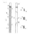
- Fig. 2(a) is a plan view showing a portion around a joint between a normal belt and an inflatable belt
- Fig. 2(b) is a plan view of an envelope-like belt
- Figs. 2(c), (d), (e) are sectional views taken along lines C-C, D-D, and E-E in Fig. 2(a), respectively.
- Fig. 3(a) is a plan view of the shoulder belt when the inflatable belt is in the deployed state
- Fig. 3(a) is a plan view of the shoulder belt when the inflatable belt is in the deployed state
- Fig. 3(a) is a plan view of the shoulder belt when the inflatable belt is in the deployed state
- Fig. 3(a) is a plan view of the shoulder belt when the inflatable belt is in the deployed
- FIG. 3(b) is a plan view of the envelope-like belt in the deployed state
- Figs. 3(c) and 3(d) are sectional views taken along lines C-C and D-D in Fig. 3(a), respectively.
- Figs. 4(a) through 4(d) are structural views of an inflatable belt.
- Fig. 5 through Fig. 8 are explanatory illustrations of a belt engagement device.
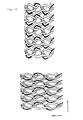
- Figs. 10 and 11 are structural views of a knit cover.
- an inflatable belt 2B comprises an envelope-like belt 10 and a knit cover 12 made of woven fabric and surrounding the envelope-like belt 10.
- the envelope-like belt 10 is formed in such a configuration that a portion confronting the chest and abdomen of an occupant in a seat has a larger area. The portion with larger area is folded to be in a band-like configuration as shown in Fig. 2(b), 2(c) and 2(d).
- the inner surface of the knit cover 12 is bonded to the outer surface of the envelope-like belt 10 by adhesive layers 11.
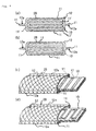
- Figs. 4(a), 4(b), 4(c), and 4(d) are schematic sectional views and sectional perspective views illustrating examples of the arrangement of the adhesive layers 11.
- the inflatable belt 2B is illustrated with enlarged in the thickness direction.
- the inflatable belt 2B has, in reality, 3-6 mm in thickness and 50-70 mm in width.
- the adhesive layers 11 bond the entire outer surface of the envelope-like belt 10 in the folded state and the inner surface of the knit cover 12.
- portions overlapped with each other of the envelope-like belt 10 in the folded state are also bonded to each other by adhesive layers 11'.
- the outer surface of the envelope-like belt 10 in the folded state is entirely bonded to the knit cover 12 and the portions overlapped with each other of the envelope-like belt 10 are not bonded to each other.
- each adhesive layer 11 is provided in a bead-like configuration.
- the bead-like adhesive layers 11 extend in the width direction of the envelope-like belt 10 and are arranged with at predetermined intervals in the longitudinal direction of the envelope-like belt 10.
- the adhesive layers 11 are arranged in a zigzag configuration extending continuously in the longitudinal direction of the envelope-like belt 10.
- Figs. 4(c), (d) show examples of a case of partially bonding the knit cover 12 to the envelope-like belt 10. It should be understand that adhesive layers having patterns other than those shown in Figs. 4(c), (d) may be employed.
- the adhesive layers may be arranged in a lattice pattern or scattered-point pattern-Furthermore, the adhesive layers may be arranged in a pattern in which the bonded areas and the non-bonded areas are reversed.
- the knit cover 12 is formed flat. Overlapped portions 12a of the knit cover 12 extending along the sides of the knit cover 12 arc bonded by the adhesive layers 11. In such a manner, the knit cover 12 is kept in a flat band-like shape.
- thermoplastic resin film of such as thermoplastic urethane is laminated on the inner surface of the knit cover 12.
- the knit cover 12 is then disposed to cover the folded envelope-like belt 10 and, after that, heated in the pressed state.
- the entire outer surface of the folded envelope-like belt and the knit cover 12 can be bonded as shown in Fig. 4(a) by heating them overall.
- they can be partially bonded as shown in Figs. 4(c), (d), by heating only portions appointed to be bonded.
- thermoplastic resin film is laminated on the outer surface of the envelope-like belt 10.
- sticky agent may be used instead of the adhesive agent,
- the sticky agent is suitably used for bonding the portions overlapped with each other of the folded envelope-like belt, just like the adhesive layers 11' of Fig. 4(a).
- the sticky agent is applied on the outer surface of the envelope-like belt 10 and, after that, the envelope-like belt 10 is folded so that the overlapped portions are bonded to each other.
- the knit cover 12 will not be separated from the envelope-like body 10 even when the knit cover 12 is pinched, so there is no chance of slippage between the knit cover 12 and the envelope-like belt 10 nor twisting of only the envelope-like belt 10 inside the knit cover 12.
- the knit cover 12 and the envelope-like belt 10 are integrally bonded to each other, the touch of the inflatable belt 2B is improved and the restraint of the occupant's body when the seat belt retractor is locked becomes more secure (there is no possibility that the knit cover 12 is drawn by the occupant's body and thus slips on the surface of the envelope-like belt 10.).
- the portions of the folded envelope-like belt 10 are also bonded to each other by the adhesive layers 11', thereby providing excellent form-maintainability of the folded envelop belt 10.
- the knit cover 12 can be stretched in the width direction, but is hardly stretched in the longitudinal direction because it is processed by hot-drawing.
- the knit cover 12 is subjected to tensile load applied to the inflatable belt 2B.
- illustrations at the left hand side show examples of way of knitting the knit cover.
- Fig. 10 shows a normal warp knitting
- Fig. 11 shows a warp knitting in which insert yarns are added to improve the strength and to allow the thickness more thin.
- One end of the inflatable belt 2B and the normal belt 2a are connected by sewing.
- the envelope-like belt 10 and the knit cover 12 are both sewn to the normal belt 2a.
- the other end of the inflatable belt 2B is connected to the tongue 17.
- the envelope-like belt 10 and the knit cover 12 are also both connected to the tongue 17.
- a gas generator is actuated in the state that the tongue 14 is engaged with the buckle, the inflatable belt 2B is inflated.
- the length of the knit cover 12 in the longitudinal direction of the inflatable belt 2B is reduced so that the inflatable belt 2B comes in close contact with the occupant, thereby securely protecting the occupant.
- illustrations at the right hand side show the state that the length of the knit cover 12 is reduced in the longitudinal direction when the inflatable belt 2B (the envelope-like belt 10) is inflated.
- the knit cover is hardly stretched in the longitudinal direction because it is processed by hot drawing.
- the knitted loops of the knit cover 12 are extended in the lateral direction when the envelope-like belt 10 is inflated. As a result of this, the knit cover 12 shrinks its length in the longitudinal direction to reduce the length of the inflatable belt 2B in the longitudinal direction.
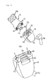
- Fig. 5(a) is a perspective view showing the tongue 14 and the buckle 16 and Fig. 5(b) is an enlarged view of the buckle shown in Fig. 5(a).
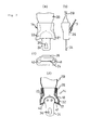
- Fig. 6(a) through Fig. 6(c) show the structure of the buckle of this embodiment
- Figs. 7(a) through 7(d) show the structure of the tongue
- Figs. 8(a) and 8(b) are a front view and a sectional view showing the state that the tongue and the buckle are engaged with each other.
- the tongue 14 comprises a tongue base 18 provided with a first guide path 21 and a second guide path 22 inside thereof, a tongue plate 24 and an anchor 26 which are connected to the tongue base 18, a ring 28 for fixing the inflatable belt 2B to the tongue base 18, and a synthetic resin cover 32 for surrounding the tongue base 18.
- the tongue base 18 has a cavity inside thereof.
- the cavity is divided into two branches extending toward the ends of the tongue (the side that is inserted into the buckle) whereby the first guide path 21 and the second guide path 22 are formed.
- Each guide path 21, 22 has an opening at the end of the tongue.
- the openings are closed by a seal member 41, 42.
- the seal member 41, 42 can be opened when gas pressure is applied, as mentioned later.
- the anchor 26 is provided with an aperture formed therein. The end of the lap belt 3 is inserted through the aperture and then connected to the anchor 26.
- the tongue plate 24 is inserted into a tongue-plate inlet 34 (Figs. 5 and 6) of the buckle 16 such that a latch hole 36 is latched with a latch pawl of a latch mechanism 38 in the buckle 16. Pressing a press button 40 provided in the buckle 16 releases the latching. At the same time, the tongue plate 24 is pushed out of the buckle 16 by a spring.
- the buckle 16 is provided with a first gas path 51 and a second gas path 52 inside thereof.
- the first gas path 51 is connected to an inflator 58 (the gas generator) through a hose 54.
- the top (the surface confronting the tongue) of the buckle 16 is provided with a seal member 61 for closing the first gas path 51 and a seal member 62 for closing the second gas path 52.
- the outer surface of the buckle 16 is covered by the synthetic resin cover 64 so that the seal members 61, 62 are formed integrally with the synthetic resin cover 64.
- the synthetic resin cover 64 is provided with tear lines formed in portions thereof above the gas paths 51, 52 so that areas surrounded by the tear lines become the seal members 61, 62. As the gas pressure is applied, the synthetic resin cover 64 is torn along the tear lines. As a result of this, the seal members 61, 62 open just like flaps as shown in Fig. 5(b).
- the lower end of the second gas path 52 opens downwardly at the bottom of the buckle 16 whereby the gas from the second gas path 52 is discharged downwardly.
- the buckle 16 and the inflator 58 have brackets 66, 68, respectively for fixing them to the vehicle body member.
- the seal member 61 is first opened by gas pressure as shown in Fig. 8(b) and the seal member 41 is then opened.
- the gas is supplied through the first guide path 21 in the tongue base 18 to the inflatable belt 2B to inflate the inflatable belt 2B.
- the gas from the inflator 58 flows upwardly through the first gas path 51 and the first guide path 21, little gas pressure is applied to the seal member 42 so that the seal members 42, 62 are still closed.
- the length of the inflatable belt 2B is reduced so that the inflatable belt closely fits to the body of the occupant, as mentioned above.
- the pressure of the gas filled in the inflatable belt 2B is applied to the seal member 42 through the second guide path 22 so that the seal member 42 opens downwardly and the seal member 62 then opens downwardly.
- the gas in the inflatable belt 2B is gradually discharged outside through the second gas path 52. This reduces the impact applied to the body of the occupant which is pushed against the inflatable belt 2B.
- the gas discharged through the second gas path 52 is discharged downwardly from the buckle 16 so as not to directly hit the occupant.
- the tongue 14 can be engaged with the buckle 16 to allow the gas to flow in the buckle 16 and the tongue 14 in the same manner as the above.
- the opened seal member 61, 42 cross the gaps between the tongue 14 and the buckle 16, thereby making the gas difficult to leak from the confronting surfaces in the lateral direction.
- the knit cover is bonded to the outer surface of the folded envelope-like belt in the aforementioned manner, the knit cover will not be deformed relative to the envelope-like belt such as being separated from nor slipping on the envelope-like body. Therefore, the repeated deformation of only the cover is prevented, thereby improving the durability of the cover.
- the envelope-like belt is prevented from twisting inside the cover. According to the present invention, the touch of the inflatable belt is also improved
- Fig. 1(a) is a perspective view of a seat on which an inflatable belt device according to an embodiment is installed and Fig. 1(b) is a perspective view of the inflatable belt device.
- Figs. 2(a) through 2(e) are structural views of the inflatable belt.
- Figs. 3(a) through 3(d) are structural views of the inflatable belt in the deployed state.
- Figs. 4(a) and 4(b) are sectional views of the inflatable belt
- Figs. 4(c) and 4(d) are perspective views showing the inside structures of the inflatable belt.
- Figs. 5(a) and 5(b) are structural views of a tongue and a buckle of the inflatable belt device according to the embodiment of the present invention.
- Figs. 6(a) through 6(c) are structural views of the buckle of Fig. 5(a).
- Figs. 7(a) through 7(d) are structural views of the tongue of Fig. 5(a).
- Figs. 8(a) and 8(b) are a front view and a sectional view of the buckle and the tongue of Fig. 5(a) in the engaged state.
- Figs. 9(a) and 9(b) are structural views of a conventional inflatable belt device.
- Figs. 10(a) and 10(b) are structural views of a knit cover.
- Figs. 11(a) and 11(b) are structural views of a knit cover.
Landscapes
- Engineering & Computer Science (AREA)
- Mechanical Engineering (AREA)
- Textile Engineering (AREA)
- Air Bags (AREA)
- Automotive Seat Belt Assembly (AREA)
Claims (7)
- Ein aufblasbarer Gurt (2B) umfasstwobei die Gewebeabdeckung (12) und der hüllenartige Gurt (10) einstückig miteinander dergestalt verbunden sind, dass die Innenfläche der Gewebeabdeckung (12) mit der Außenfläche des gefalteten Körpers verbunden ist,einen hüllenartigen Gurt (10), der in einer bandförmigen Anordnung gefaltet und durch eingeleitetes Gas aufblasbar ist, dadurch gekennzeichnet, dass ereine Gewebeabdeckung (12) ausdehnbar zum Umschließen des gefalteten Körpers des hüllenartigen Gurtes (10) aufweist, wobei die Gewebeabdeckung (12) in die Breite, jedoch kaum in die Länge gedehnt werden kann,
so dass die gewirkten Schlingen der Gewebeabdeckung (12) in der seitlichen Richtung gedehnt werden, wenn der hüllenartige Gurt (10) aufgeblasen wird und dass daraus resultiert, dass sich die Gewebeabdeckung (12) in seiner Länge in Längsrichtung zusammenzieht, um die Länge des aufblasbaren Gurtes (2B) in Längsrichtung zu reduzieren. - Aufblasbarer Gurt nach Anspruch 1, dadurch gekennzeichnet, dass im wesentlichen die gesamte Außenfläche des gefalteten Körpers mit der Innenfläche der Gewebeabdeckung (12) verbunden ist.
- Aufblasbarer Gurt nach Anspruch 1, dadurch gekennzeichnet, dass Abschnitte der Außenfläche des gefalteten Körpers mit der Innenfläche der Gewebeabdeckung (12) verbunden sind.
- Aufblasbarer Gurt nach Anspruch 3, dadurch gekennzeichnet, dass die verbundenen Abschnitte zwischen dem gefalteten Körper und der Gewebeabdeckung (12) in Abständen in Längsrichtung des gefalteten Körpers angeordnet sind.
- Aufblasbarer Gurt nach einem der voranstehenden Ansprüche, dadurch gekennzeichnet, dass die Verbindung durch das Erwärmen von themoplastischem Harz, das zwischen den gefalteten Körper und der Gewebeabdeckung (12) eingebracht wird, vorgesehen ist.
- Aufblasbarer Gurt nach einem der voranstehenden Ansprüche, dadurch gekennzeichnet, dass der Verbindungabschnitt zwischen der Gewebeabdeckung (12) und dem gefalteten Körper von solcher Festigkeit ist, dass die Verbindung gelöst wird, wenn der gefaltete Körper aufgeblasen wird.
- Aufblasbarer Gurt nach einem der voranstehenden Ansprüche, dadurch gekennzeichnet, dass in gefaltetem Zustand überdeckte Teile des hüllenartigen Gurtes (10) miteinander verbunden sind.
Applications Claiming Priority (2)
| Application Number | Priority Date | Filing Date | Title |
|---|---|---|---|
| JP33287797 | 1997-12-03 | ||
| JP33287797A JP3598781B2 (ja) | 1997-12-03 | 1997-12-03 | エアベルト及びエアベルト装置 |
Publications (3)
| Publication Number | Publication Date |
|---|---|
| EP0933263A2 EP0933263A2 (de) | 1999-08-04 |
| EP0933263A3 EP0933263A3 (de) | 1999-08-11 |
| EP0933263B1 true EP0933263B1 (de) | 2003-06-11 |
Family
ID=18259808
Family Applications (1)
| Application Number | Title | Priority Date | Filing Date |
|---|---|---|---|
| EP98122932A Expired - Lifetime EP0933263B1 (de) | 1997-12-03 | 1998-12-03 | Aufblasbare Sicherheitsgurtvorrichtung |
Country Status (4)
| Country | Link |
|---|---|
| US (1) | US6082763A (de) |
| EP (1) | EP0933263B1 (de) |
| JP (1) | JP3598781B2 (de) |
| DE (1) | DE69815488T2 (de) |
Cited By (1)
| Publication number | Priority date | Publication date | Assignee | Title |
|---|---|---|---|---|
| US7568726B2 (en) | 2005-09-26 | 2009-08-04 | Takata Corporation | Air belt apparatus |
Families Citing this family (46)
| Publication number | Priority date | Publication date | Assignee | Title |
|---|---|---|---|---|
| US6109647A (en) * | 1997-12-15 | 2000-08-29 | Honda Giken Kogyo Kabushiki Kaisha | Seat-occupant restraining apparatus |
| JP3758367B2 (ja) * | 1998-05-25 | 2006-03-22 | タカタ株式会社 | エアベルト装置及びタング |
| US6837079B1 (en) * | 1998-06-09 | 2005-01-04 | Takata Corporation | Warp knitted fabric for air belt cover |
| DE69912886T2 (de) * | 1998-07-06 | 2004-09-02 | Takata Corp. | Sicherheitsgurt für ein Kraftfahrzeug |
| JP3809736B2 (ja) * | 1998-12-24 | 2006-08-16 | タカタ株式会社 | エアベルト装置 |
| JP4135273B2 (ja) * | 1999-01-13 | 2008-08-20 | タカタ株式会社 | エアベルトカバー用たて編み物及びエアベルト装置 |
| DE19940776A1 (de) * | 1999-08-27 | 2001-03-01 | Delphi Tech Inc | Luftsackmodul |
| JP3899740B2 (ja) * | 1999-09-24 | 2007-03-28 | タカタ株式会社 | エアベルト及びエアベルト装置 |
| JP4527268B2 (ja) * | 2000-03-02 | 2010-08-18 | タカタ株式会社 | エアベルト用係止装置 |
| JP4380021B2 (ja) | 2000-05-11 | 2009-12-09 | タカタ株式会社 | エアベルト装置 |
| US6709063B1 (en) * | 2000-06-15 | 2004-03-23 | Keiji Furukawa | Automobile seat belt structure and assist apparatus thereof |
| US6550805B1 (en) * | 2002-02-01 | 2003-04-22 | Ford Global Technologies, Llc | Occupant restraint belt with inflatable presenter |
| GB2410010B (en) * | 2004-01-19 | 2007-01-31 | Autoliv Dev | Improvements in or relating to an air-bag arrangement |
| GB2410009A (en) * | 2004-01-19 | 2005-07-20 | Autoliv Dev | An air-bag unit |
| JP5011779B2 (ja) * | 2005-04-04 | 2012-08-29 | タカタ株式会社 | エアベルト装置 |
| JP2007022212A (ja) * | 2005-07-13 | 2007-02-01 | Takata Corp | 乗員拘束ベルト及び乗員拘束装置 |
| JP4670531B2 (ja) * | 2005-08-02 | 2011-04-13 | タカタ株式会社 | エアベルト及びエアベルト装置 |
| JP4454028B2 (ja) * | 2005-11-04 | 2010-04-21 | トヨタ自動車株式会社 | 車両用エアベルト装置 |
| WO2007145551A1 (en) * | 2006-06-16 | 2007-12-21 | Autoliv Development Ab | Anti-twist airbag in belt |
| US7980590B2 (en) | 2008-03-19 | 2011-07-19 | Amsafe, Inc. | Inflatable personal restraint systems having web-mounted inflators and associated methods of use and manufacture |
| US7665761B1 (en) | 2008-03-27 | 2010-02-23 | Amsafe, Inc. | Inflatable personal restraint systems and associated methods of use and manufacture |
| CN102066159B (zh) * | 2008-06-20 | 2014-07-16 | 福特全球技术公司 | 充气式安全带系统 |
| JP5446657B2 (ja) * | 2009-09-18 | 2014-03-19 | タカタ株式会社 | エアベルト及びエアベルト装置 |
| JP5502573B2 (ja) * | 2010-04-12 | 2014-05-28 | タカタ株式会社 | エアベルト装置 |
| US8469397B2 (en) | 2011-04-13 | 2013-06-25 | Amsafe, Inc. | Stitch patterns for restraint-mounted airbags and associated systems and methods |
| USD688156S1 (en) | 2011-05-16 | 2013-08-20 | Amsafe, Inc. | Connector for a seatbelt airbag |
| KR101305720B1 (ko) * | 2011-06-03 | 2013-09-09 | 현대자동차주식회사 | 차량용 에어벨트 장치 |
| US8439398B2 (en) | 2011-07-29 | 2013-05-14 | Amsafe, Inc. | Inflator connectors for inflatable personal restraints and associated systems and methods |
| US8523220B1 (en) | 2012-03-19 | 2013-09-03 | Amsafe, Inc. | Structure mounted airbag assemblies and associated systems and methods |
| US9511866B2 (en) | 2012-03-19 | 2016-12-06 | Amsafe, Inc. | Structure mounted airbag assemblies and associated systems and methods |
| CN103786678B (zh) * | 2012-10-31 | 2016-02-03 | 比亚迪股份有限公司 | 一种充气安全带装置 |
| US9260076B2 (en) * | 2013-07-23 | 2016-02-16 | Honda Motor Co., Ltd. | Method, system and apparatus for stabilizing vehicle occupant's shoulder during side collision impact |
| WO2015061494A1 (en) * | 2013-10-23 | 2015-04-30 | The Regents Of The University Of California | Ventilated seatbelt for efficient cooling and heating of vehicle passengers |
| US9434339B2 (en) * | 2014-08-27 | 2016-09-06 | Autoliv Asp, Inc. | Inflatable seat belt with a tethered gas delivery fill tube |
| US9352839B2 (en) | 2014-10-02 | 2016-05-31 | Amsafe, Inc. | Active positioning airbag assembly and associated systems and methods |
| US9944245B2 (en) | 2015-03-28 | 2018-04-17 | Amsafe, Inc. | Extending pass-through airbag occupant restraint systems, and associated systems and methods |
| EP3283336B1 (de) | 2015-04-11 | 2019-11-20 | AmSafe, Inc. | Aktives entlüftungssystem für airbag |
| JP6492366B2 (ja) * | 2015-08-21 | 2019-04-03 | 本田技研工業株式会社 | 車両の乗員拘束装置 |
| US10604259B2 (en) | 2016-01-20 | 2020-03-31 | Amsafe, Inc. | Occupant restraint systems having extending restraints, and associated systems and methods |
| JP6254634B2 (ja) * | 2016-03-31 | 2017-12-27 | 株式会社Subaru | 乗員保護装置 |
| US11285910B2 (en) * | 2017-05-26 | 2022-03-29 | Daimler Ag | Safety belt for a vehicle |
| US10569735B2 (en) * | 2017-12-07 | 2020-02-25 | Ford Global Technologies, Llc | Vehicle seat belt system having uniform air delivery |
| US10479162B2 (en) * | 2017-12-07 | 2019-11-19 | Ford Global Technologies, Llc | Vehicle seat belt having tubes for air delivery |
| US10442392B2 (en) | 2017-12-07 | 2019-10-15 | Ford Global Technologies, Llc | Vehicle seat belt system having air distribution manifold |
| US20190344743A1 (en) * | 2018-05-14 | 2019-11-14 | Ford Global Technologies, Llc | Seatbelt assembly |
| US11673496B1 (en) * | 2022-03-17 | 2023-06-13 | GM Global Technology Operations LLC | Targeted occupant thermal comfort based on seat belt |
Family Cites Families (17)
| Publication number | Priority date | Publication date | Assignee | Title |
|---|---|---|---|---|
| US3801156A (en) | 1971-11-15 | 1974-04-02 | H Granig | Safety-belt |
| US3841654A (en) | 1972-09-21 | 1974-10-15 | Allied Chem | Vehicle safety system |
| US3820842A (en) * | 1972-11-17 | 1974-06-28 | Allied Chem | Slip tongue with inflator band |
| US3877719A (en) * | 1972-11-24 | 1975-04-15 | Allied Chem | Inflator-connector for inflatable vehicle safety belts |
| DE2358070A1 (de) * | 1972-11-27 | 1974-06-06 | Nissan Motor | Sicherheitsgurt |
| US3970329A (en) * | 1973-01-10 | 1976-07-20 | Allied Chemical Corporation | Inflatable band restraint stitching |
| US3866940A (en) * | 1973-01-11 | 1975-02-18 | Allied Chem | Differentially inflatable restraining band for vehicles |
| US4348037A (en) * | 1980-06-03 | 1982-09-07 | Thiokol Corporation | Safety cushion attachable to belt-type restraints |
| US5062662A (en) * | 1990-05-16 | 1991-11-05 | Cameron Robert W | Vehicle seatbelt having an integral airbag |
| JP3057112B2 (ja) * | 1991-09-24 | 2000-06-26 | タカタ株式会社 | インフレータブルシートベルト装置 |
| JP3110881B2 (ja) * | 1992-08-06 | 2000-11-20 | タカタ株式会社 | インフレータブルシートベルト装置 |
| JP3278075B2 (ja) | 1992-08-06 | 2002-04-30 | タカタ株式会社 | インフレータブルシートベルト装置 |
| JP3113081B2 (ja) * | 1992-08-18 | 2000-11-27 | タカタ株式会社 | インフレータブルシートベルト装置 |
| CA2102334A1 (en) * | 1993-11-03 | 1995-05-04 | Hang-Sup Ohm | Automobile safety air belt with air bag |
| US5839753A (en) * | 1997-03-31 | 1998-11-24 | Simula Inc. | Inflatable tubular torso restraint system |
| US5851055A (en) * | 1997-03-13 | 1998-12-22 | Universal Propulsion Company, Inc. | Inflatable passenger-size adjustable torso belt system including enclosure mount and method of passenger restraint |
| US5947513A (en) * | 1997-07-03 | 1999-09-07 | Lehto; Mark R. | Passenger restraint system |
-
1997
- 1997-12-03 JP JP33287797A patent/JP3598781B2/ja not_active Expired - Fee Related
-
1998
- 1998-12-03 EP EP98122932A patent/EP0933263B1/de not_active Expired - Lifetime
- 1998-12-03 US US09/205,097 patent/US6082763A/en not_active Expired - Lifetime
- 1998-12-03 DE DE69815488T patent/DE69815488T2/de not_active Expired - Lifetime
Cited By (1)
| Publication number | Priority date | Publication date | Assignee | Title |
|---|---|---|---|---|
| US7568726B2 (en) | 2005-09-26 | 2009-08-04 | Takata Corporation | Air belt apparatus |
Also Published As
| Publication number | Publication date |
|---|---|
| JP3598781B2 (ja) | 2004-12-08 |
| EP0933263A2 (de) | 1999-08-04 |
| US6082763A (en) | 2000-07-04 |
| DE69815488D1 (de) | 2003-07-17 |
| JPH11165603A (ja) | 1999-06-22 |
| EP0933263A3 (de) | 1999-08-11 |
| DE69815488T2 (de) | 2003-12-18 |
Similar Documents
| Publication | Publication Date | Title |
|---|---|---|
| EP0933263B1 (de) | Aufblasbare Sicherheitsgurtvorrichtung | |
| USRE37280E1 (en) | Inflatable seat belt having defined shape | |
| EP0901944B1 (de) | Aufblasbare Sicherheitsgurtvorrichtung | |
| EP0904993B1 (de) | Aufblasbare Sicherheitsgurtvorrichtung | |
| EP0962363B1 (de) | Luftsack | |
| US6419264B1 (en) | Air-belt device and method | |
| KR20010052969A (ko) | 팽창 영역을 갖는 벨트장치 및 고정 방법 | |
| US5354096A (en) | Inflatable seatbelt system | |
| JP3762459B2 (ja) | 側部用エアバッグ装置 | |
| JP7484860B2 (ja) | 乗員保護装置 | |
| JP4670531B2 (ja) | エアベルト及びエアベルト装置 | |
| JP3760632B2 (ja) | エアベルト及びエアベルト装置 | |
| JPH11348706A5 (de) | ||
| US6082759A (en) | Inflatable vehicle occupant protection device module and method | |
| JP2005153726A (ja) | エアバッグ及びエアバッグ装置 | |
| JPH06262994A (ja) | インフレータブルシートベルト装置 | |
| EP0964087B1 (de) | Herstellung eines Sacks für einen aufblasbaren Sicherheitsgurt, und Sicherheitsgurt | |
| JP3900725B2 (ja) | エアベルト及びエアベルト装置 | |
| JP3526313B2 (ja) | シートベルト装置の膨張構造体 | |
| JP3502763B2 (ja) | エアベルト装置 | |
| JPH06262997A (ja) | テンションレスインフレータブルシートベルト装置 | |
| JP2001158317A (ja) | エアベルト装置 | |
| JP2001322522A (ja) | エアベルト装置 | |
| JP3721785B2 (ja) | 乗員保護装置 | |
| JPH11255057A (ja) | エアベルト装置 |
Legal Events
| Date | Code | Title | Description |
|---|---|---|---|
| PUAI | Public reference made under article 153(3) epc to a published international application that has entered the european phase |
Free format text: ORIGINAL CODE: 0009012 |
|
| PUAL | Search report despatched |
Free format text: ORIGINAL CODE: 0009013 |
|
| AK | Designated contracting states |
Kind code of ref document: A2 Designated state(s): DE GB |
|
| AX | Request for extension of the european patent |
Free format text: AL;LT;LV;MK;RO;SI |
|
| AK | Designated contracting states |
Kind code of ref document: A3 Designated state(s): AT BE CH CY DE DK ES FI FR GB GR IE IT LI LU MC NL PT SE |
|
| AX | Request for extension of the european patent |
Free format text: AL;LT;LV;MK;RO;SI |
|
| 17P | Request for examination filed |
Effective date: 20000209 |
|
| AKX | Designation fees paid |
Free format text: DE GB |
|
| 17Q | First examination report despatched |
Effective date: 20011116 |
|
| GRAH | Despatch of communication of intention to grant a patent |
Free format text: ORIGINAL CODE: EPIDOS IGRA |
|
| GRAH | Despatch of communication of intention to grant a patent |
Free format text: ORIGINAL CODE: EPIDOS IGRA |
|
| GRAA | (expected) grant |
Free format text: ORIGINAL CODE: 0009210 |
|
| AK | Designated contracting states |
Designated state(s): DE GB |
|
| REG | Reference to a national code |
Ref country code: GB Ref legal event code: FG4D |
|
| REF | Corresponds to: |
Ref document number: 69815488 Country of ref document: DE Date of ref document: 20030717 Kind code of ref document: P |
|
| PLBE | No opposition filed within time limit |
Free format text: ORIGINAL CODE: 0009261 |
|
| STAA | Information on the status of an ep patent application or granted ep patent |
Free format text: STATUS: NO OPPOSITION FILED WITHIN TIME LIMIT |
|
| 26N | No opposition filed |
Effective date: 20040312 |
|
| PGFP | Annual fee paid to national office [announced via postgrant information from national office to epo] |
Ref country code: DE Payment date: 20131127 Year of fee payment: 16 Ref country code: GB Payment date: 20131127 Year of fee payment: 16 |
|
| REG | Reference to a national code |
Ref country code: DE Ref legal event code: R119 Ref document number: 69815488 Country of ref document: DE |
|
| REG | Reference to a national code |
Ref country code: DE Ref legal event code: R082 Ref document number: 69815488 Country of ref document: DE Representative=s name: GRAMM, LINS & PARTNER PATENT- UND RECHTSANWAEL, DE |
|
| GBPC | Gb: european patent ceased through non-payment of renewal fee |
Effective date: 20141203 |
|
| PG25 | Lapsed in a contracting state [announced via postgrant information from national office to epo] |
Ref country code: GB Free format text: LAPSE BECAUSE OF NON-PAYMENT OF DUE FEES Effective date: 20141203 Ref country code: DE Free format text: LAPSE BECAUSE OF NON-PAYMENT OF DUE FEES Effective date: 20150701 |