EP0932583B1 - Verwendung einer elektrolysevorrichtung zur reduzierung bzw. verhinderung der steinbildung - Google Patents
Verwendung einer elektrolysevorrichtung zur reduzierung bzw. verhinderung der steinbildung Download PDFInfo
- Publication number
- EP0932583B1 EP0932583B1 EP97942143A EP97942143A EP0932583B1 EP 0932583 B1 EP0932583 B1 EP 0932583B1 EP 97942143 A EP97942143 A EP 97942143A EP 97942143 A EP97942143 A EP 97942143A EP 0932583 B1 EP0932583 B1 EP 0932583B1
- Authority
- EP
- European Patent Office
- Prior art keywords
- electrodes
- use according
- aqueous solution
- electrolysis chamber
- electrolysis
- Prior art date
- Legal status (The legal status is an assumption and is not a legal conclusion. Google has not performed a legal analysis and makes no representation as to the accuracy of the status listed.)
- Expired - Lifetime
Links
- 239000007864 aqueous solution Substances 0.000 claims abstract description 50
- 238000005868 electrolysis reaction Methods 0.000 claims abstract description 47
- 230000015572 biosynthetic process Effects 0.000 claims abstract description 28
- 239000000203 mixture Substances 0.000 claims abstract description 4
- XLYOFNOQVPJJNP-UHFFFAOYSA-N water Substances O XLYOFNOQVPJJNP-UHFFFAOYSA-N 0.000 claims description 39
- 239000002245 particle Substances 0.000 claims description 31
- OKTJSMMVPCPJKN-UHFFFAOYSA-N Carbon Chemical compound [C] OKTJSMMVPCPJKN-UHFFFAOYSA-N 0.000 claims description 16
- 229910021532 Calcite Inorganic materials 0.000 claims description 10
- 229910002804 graphite Inorganic materials 0.000 claims description 10
- 239000010439 graphite Substances 0.000 claims description 10
- 239000011575 calcium Substances 0.000 claims description 7
- OYPRJOBELJOOCE-UHFFFAOYSA-N Calcium Chemical compound [Ca] OYPRJOBELJOOCE-UHFFFAOYSA-N 0.000 claims description 6
- 239000004020 conductor Substances 0.000 claims description 6
- 229910052791 calcium Inorganic materials 0.000 claims description 5
- FYYHWMGAXLPEAU-UHFFFAOYSA-N Magnesium Chemical compound [Mg] FYYHWMGAXLPEAU-UHFFFAOYSA-N 0.000 claims description 4
- 229910052749 magnesium Inorganic materials 0.000 claims description 4
- 239000011777 magnesium Substances 0.000 claims description 4
- 239000004033 plastic Substances 0.000 claims description 4
- 229920003023 plastic Polymers 0.000 claims description 4
- 239000002699 waste material Substances 0.000 claims description 4
- 239000011521 glass Substances 0.000 claims description 3
- 239000008233 hard water Substances 0.000 claims description 3
- 229910001200 Ferrotitanium Inorganic materials 0.000 claims description 2
- 150000004649 carbonic acid derivatives Chemical class 0.000 claims description 2
- 239000012811 non-conductive material Substances 0.000 claims description 2
- 125000006850 spacer group Chemical group 0.000 claims description 2
- 150000003467 sulfuric acid derivatives Chemical class 0.000 claims description 2
- 229910000510 noble metal Inorganic materials 0.000 claims 2
- BVKZGUZCCUSVTD-UHFFFAOYSA-N carbonic acid Chemical class OC(O)=O BVKZGUZCCUSVTD-UHFFFAOYSA-N 0.000 claims 1
- 238000000034 method Methods 0.000 abstract description 13
- 239000004575 stone Substances 0.000 description 24
- 239000003651 drinking water Substances 0.000 description 9
- 235000020188 drinking water Nutrition 0.000 description 9
- 239000000243 solution Substances 0.000 description 9
- 230000000694 effects Effects 0.000 description 8
- 239000000463 material Substances 0.000 description 8
- 239000000126 substance Substances 0.000 description 6
- 238000000926 separation method Methods 0.000 description 5
- 230000008859 change Effects 0.000 description 4
- 230000005684 electric field Effects 0.000 description 4
- 150000003839 salts Chemical class 0.000 description 4
- 238000012360 testing method Methods 0.000 description 4
- BVKZGUZCCUSVTD-UHFFFAOYSA-M Bicarbonate Chemical class OC([O-])=O BVKZGUZCCUSVTD-UHFFFAOYSA-M 0.000 description 3
- BVKZGUZCCUSVTD-UHFFFAOYSA-L Carbonate Chemical compound [O-]C([O-])=O BVKZGUZCCUSVTD-UHFFFAOYSA-L 0.000 description 3
- XEEYBQQBJWHFJM-UHFFFAOYSA-N Iron Chemical compound [Fe] XEEYBQQBJWHFJM-UHFFFAOYSA-N 0.000 description 3
- 238000010438 heat treatment Methods 0.000 description 3
- 150000002500 ions Chemical class 0.000 description 3
- 229910001425 magnesium ion Inorganic materials 0.000 description 3
- 239000010970 precious metal Substances 0.000 description 3
- 238000001556 precipitation Methods 0.000 description 3
- 230000008569 process Effects 0.000 description 3
- 230000009467 reduction Effects 0.000 description 3
- CURLTUGMZLYLDI-UHFFFAOYSA-N Carbon dioxide Chemical compound O=C=O CURLTUGMZLYLDI-UHFFFAOYSA-N 0.000 description 2
- JLVVSXFLKOJNIY-UHFFFAOYSA-N Magnesium ion Chemical compound [Mg+2] JLVVSXFLKOJNIY-UHFFFAOYSA-N 0.000 description 2
- 229910002651 NO3 Inorganic materials 0.000 description 2
- NHNBFGGVMKEFGY-UHFFFAOYSA-N Nitrate Chemical compound [O-][N+]([O-])=O NHNBFGGVMKEFGY-UHFFFAOYSA-N 0.000 description 2
- 239000004902 Softening Agent Substances 0.000 description 2
- PPBRXRYQALVLMV-UHFFFAOYSA-N Styrene Chemical compound C=CC1=CC=CC=C1 PPBRXRYQALVLMV-UHFFFAOYSA-N 0.000 description 2
- 239000002253 acid Substances 0.000 description 2
- 229910001424 calcium ion Inorganic materials 0.000 description 2
- 239000001569 carbon dioxide Substances 0.000 description 2
- 229910002092 carbon dioxide Inorganic materials 0.000 description 2
- 239000003344 environmental pollutant Substances 0.000 description 2
- 239000011888 foil Substances 0.000 description 2
- JGJLWPGRMCADHB-UHFFFAOYSA-N hypobromite Chemical compound Br[O-] JGJLWPGRMCADHB-UHFFFAOYSA-N 0.000 description 2
- WQYVRQLZKVEZGA-UHFFFAOYSA-N hypochlorite Chemical compound Cl[O-] WQYVRQLZKVEZGA-UHFFFAOYSA-N 0.000 description 2
- 229910052742 iron Inorganic materials 0.000 description 2
- -1 iron ions Chemical class 0.000 description 2
- 229910052751 metal Inorganic materials 0.000 description 2
- 239000002184 metal Substances 0.000 description 2
- 239000008239 natural water Substances 0.000 description 2
- 230000003647 oxidation Effects 0.000 description 2
- 238000007254 oxidation reaction Methods 0.000 description 2
- 231100000719 pollutant Toxicity 0.000 description 2
- 239000011148 porous material Substances 0.000 description 2
- 238000002360 preparation method Methods 0.000 description 2
- 230000001105 regulatory effect Effects 0.000 description 2
- 230000002441 reversible effect Effects 0.000 description 2
- CXMXRPHRNRROMY-UHFFFAOYSA-N sebacic acid Chemical compound OC(=O)CCCCCCCCC(O)=O CXMXRPHRNRROMY-UHFFFAOYSA-N 0.000 description 2
- 238000003786 synthesis reaction Methods 0.000 description 2
- VEXZGXHMUGYJMC-UHFFFAOYSA-M Chloride anion Chemical compound [Cl-] VEXZGXHMUGYJMC-UHFFFAOYSA-M 0.000 description 1
- 235000008733 Citrus aurantifolia Nutrition 0.000 description 1
- XFXPMWWXUTWYJX-UHFFFAOYSA-N Cyanide Chemical compound N#[C-] XFXPMWWXUTWYJX-UHFFFAOYSA-N 0.000 description 1
- UFHFLCQGNIYNRP-UHFFFAOYSA-N Hydrogen Chemical compound [H][H] UFHFLCQGNIYNRP-UHFFFAOYSA-N 0.000 description 1
- DGAQECJNVWCQMB-PUAWFVPOSA-M Ilexoside XXIX Chemical compound C[C@@H]1CC[C@@]2(CC[C@@]3(C(=CC[C@H]4[C@]3(CC[C@@H]5[C@@]4(CC[C@@H](C5(C)C)OS(=O)(=O)[O-])C)C)[C@@H]2[C@]1(C)O)C)C(=O)O[C@H]6[C@@H]([C@H]([C@@H]([C@H](O6)CO)O)O)O.[Na+] DGAQECJNVWCQMB-PUAWFVPOSA-M 0.000 description 1
- GRYLNZFGIOXLOG-UHFFFAOYSA-N Nitric acid Chemical compound O[N+]([O-])=O GRYLNZFGIOXLOG-UHFFFAOYSA-N 0.000 description 1
- 239000004677 Nylon Substances 0.000 description 1
- QAOWNCQODCNURD-UHFFFAOYSA-L Sulfate Chemical compound [O-]S([O-])(=O)=O QAOWNCQODCNURD-UHFFFAOYSA-L 0.000 description 1
- 235000011941 Tilia x europaea Nutrition 0.000 description 1
- 230000009471 action Effects 0.000 description 1
- 239000012736 aqueous medium Substances 0.000 description 1
- QVGXLLKOCUKJST-UHFFFAOYSA-N atomic oxygen Chemical compound [O] QVGXLLKOCUKJST-UHFFFAOYSA-N 0.000 description 1
- 230000000903 blocking effect Effects 0.000 description 1
- 238000006243 chemical reaction Methods 0.000 description 1
- 239000007795 chemical reaction product Substances 0.000 description 1
- KRVSOGSZCMJSLX-UHFFFAOYSA-L chromic acid Substances O[Cr](O)(=O)=O KRVSOGSZCMJSLX-UHFFFAOYSA-L 0.000 description 1
- 238000004140 cleaning Methods 0.000 description 1
- 230000000052 comparative effect Effects 0.000 description 1
- 150000001875 compounds Chemical class 0.000 description 1
- 230000003111 delayed effect Effects 0.000 description 1
- 238000013461 design Methods 0.000 description 1
- 238000003795 desorption Methods 0.000 description 1
- 230000006866 deterioration Effects 0.000 description 1
- 238000010494 dissociation reaction Methods 0.000 description 1
- 230000005593 dissociations Effects 0.000 description 1
- 238000003487 electrochemical reaction Methods 0.000 description 1
- 239000007772 electrode material Substances 0.000 description 1
- 239000003792 electrolyte Substances 0.000 description 1
- 238000006735 epoxidation reaction Methods 0.000 description 1
- 238000011156 evaluation Methods 0.000 description 1
- 238000002474 experimental method Methods 0.000 description 1
- 239000004744 fabric Substances 0.000 description 1
- AWJWCTOOIBYHON-UHFFFAOYSA-N furo[3,4-b]pyrazine-5,7-dione Chemical compound C1=CN=C2C(=O)OC(=O)C2=N1 AWJWCTOOIBYHON-UHFFFAOYSA-N 0.000 description 1
- 229910052739 hydrogen Inorganic materials 0.000 description 1
- 239000001257 hydrogen Substances 0.000 description 1
- XLYOFNOQVPJJNP-UHFFFAOYSA-M hydroxide Chemical compound [OH-] XLYOFNOQVPJJNP-UHFFFAOYSA-M 0.000 description 1
- 150000004679 hydroxides Chemical class 0.000 description 1
- 230000003993 interaction Effects 0.000 description 1
- 238000005342 ion exchange Methods 0.000 description 1
- 150000002506 iron compounds Chemical class 0.000 description 1
- 239000004571 lime Substances 0.000 description 1
- 239000007788 liquid Substances 0.000 description 1
- VTHJTEIRLNZDEV-UHFFFAOYSA-L magnesium dihydroxide Chemical compound [OH-].[OH-].[Mg+2] VTHJTEIRLNZDEV-UHFFFAOYSA-L 0.000 description 1
- 239000000347 magnesium hydroxide Substances 0.000 description 1
- 229910001862 magnesium hydroxide Inorganic materials 0.000 description 1
- 238000012423 maintenance Methods 0.000 description 1
- 230000007246 mechanism Effects 0.000 description 1
- 239000002609 medium Substances 0.000 description 1
- 150000002739 metals Chemical class 0.000 description 1
- OJURWUUOVGOHJZ-UHFFFAOYSA-N methyl 2-[(2-acetyloxyphenyl)methyl-[2-[(2-acetyloxyphenyl)methyl-(2-methoxy-2-oxoethyl)amino]ethyl]amino]acetate Chemical compound C=1C=CC=C(OC(C)=O)C=1CN(CC(=O)OC)CCN(CC(=O)OC)CC1=CC=CC=C1OC(C)=O OJURWUUOVGOHJZ-UHFFFAOYSA-N 0.000 description 1
- 229910017604 nitric acid Inorganic materials 0.000 description 1
- 230000006911 nucleation Effects 0.000 description 1
- 238000010899 nucleation Methods 0.000 description 1
- 229920001778 nylon Polymers 0.000 description 1
- 238000010943 off-gassing Methods 0.000 description 1
- 150000002894 organic compounds Chemical class 0.000 description 1
- 229910052760 oxygen Inorganic materials 0.000 description 1
- 239000001301 oxygen Substances 0.000 description 1
- 238000005192 partition Methods 0.000 description 1
- 230000000737 periodic effect Effects 0.000 description 1
- 239000002244 precipitate Substances 0.000 description 1
- 238000002203 pretreatment Methods 0.000 description 1
- 230000002265 prevention Effects 0.000 description 1
- 238000011084 recovery Methods 0.000 description 1
- 230000008929 regeneration Effects 0.000 description 1
- 238000011069 regeneration method Methods 0.000 description 1
- 238000009877 rendering Methods 0.000 description 1
- 238000001223 reverse osmosis Methods 0.000 description 1
- 238000009938 salting Methods 0.000 description 1
- 239000013535 sea water Substances 0.000 description 1
- 239000011734 sodium Substances 0.000 description 1
- 229910052708 sodium Inorganic materials 0.000 description 1
- 238000001179 sorption measurement Methods 0.000 description 1
- 238000004659 sterilization and disinfection Methods 0.000 description 1
- 238000010998 test method Methods 0.000 description 1
- 238000005406 washing Methods 0.000 description 1
- 239000002351 wastewater Substances 0.000 description 1
Images
Classifications
-
- C—CHEMISTRY; METALLURGY
- C02—TREATMENT OF WATER, WASTE WATER, SEWAGE, OR SLUDGE
- C02F—TREATMENT OF WATER, WASTE WATER, SEWAGE, OR SLUDGE
- C02F1/00—Treatment of water, waste water, or sewage
- C02F1/46—Treatment of water, waste water, or sewage by electrochemical methods
- C02F1/4602—Treatment of water, waste water, or sewage by electrochemical methods for prevention or elimination of deposits
-
- C—CHEMISTRY; METALLURGY
- C02—TREATMENT OF WATER, WASTE WATER, SEWAGE, OR SLUDGE
- C02F—TREATMENT OF WATER, WASTE WATER, SEWAGE, OR SLUDGE
- C02F1/00—Treatment of water, waste water, or sewage
- C02F1/46—Treatment of water, waste water, or sewage by electrochemical methods
- C02F1/461—Treatment of water, waste water, or sewage by electrochemical methods by electrolysis
- C02F1/46104—Devices therefor; Their operating or servicing
- C02F1/46109—Electrodes
- C02F1/46114—Electrodes in particulate form or with conductive and/or non conductive particles between them
-
- C—CHEMISTRY; METALLURGY
- C02—TREATMENT OF WATER, WASTE WATER, SEWAGE, OR SLUDGE
- C02F—TREATMENT OF WATER, WASTE WATER, SEWAGE, OR SLUDGE
- C02F1/00—Treatment of water, waste water, or sewage
- C02F1/46—Treatment of water, waste water, or sewage by electrochemical methods
- C02F1/461—Treatment of water, waste water, or sewage by electrochemical methods by electrolysis
- C02F1/46104—Devices therefor; Their operating or servicing
- C02F1/46109—Electrodes
- C02F2001/46128—Bipolar electrodes
-
- C—CHEMISTRY; METALLURGY
- C02—TREATMENT OF WATER, WASTE WATER, SEWAGE, OR SLUDGE
- C02F—TREATMENT OF WATER, WASTE WATER, SEWAGE, OR SLUDGE
- C02F2201/00—Apparatus for treatment of water, waste water or sewage
- C02F2201/46—Apparatus for electrochemical processes
- C02F2201/461—Electrolysis apparatus
- C02F2201/46105—Details relating to the electrolytic devices
- C02F2201/4612—Controlling or monitoring
- C02F2201/46125—Electrical variables
- C02F2201/4613—Inversing polarity
-
- C—CHEMISTRY; METALLURGY
- C02—TREATMENT OF WATER, WASTE WATER, SEWAGE, OR SLUDGE
- C02F—TREATMENT OF WATER, WASTE WATER, SEWAGE, OR SLUDGE
- C02F2201/00—Apparatus for treatment of water, waste water or sewage
- C02F2201/46—Apparatus for electrochemical processes
- C02F2201/461—Electrolysis apparatus
- C02F2201/46105—Details relating to the electrolytic devices
- C02F2201/4616—Power supply
- C02F2201/4617—DC only
-
- C—CHEMISTRY; METALLURGY
- C02—TREATMENT OF WATER, WASTE WATER, SEWAGE, OR SLUDGE
- C02F—TREATMENT OF WATER, WASTE WATER, SEWAGE, OR SLUDGE
- C02F2301/00—General aspects of water treatment
- C02F2301/02—Fluid flow conditions
- C02F2301/024—Turbulent
Definitions
- the invention relates to the use of an electrolysis device for reduction or preventing stone formation from aqueous solutions.
- bipolar Electrodes that are conductive and not as fixed beds conductive particle or as a fluidized bed conductive particle can be trained in higher electrolysis processes Enable space-time yields.
- Such methods are, for example in Electrochimica Acta 22, 347-352 (1977) and in Electrochimica Acta 22, 1087-1091 (1977) for the preparation of hypobromite, for epoxidation of styrene, for synthesis of the dimethyl ester of sebacic acid and for the preparation of Hypochlorite from sea water is described.
- Bipolar electrodes have not been used in water treatment, however.
- GB-A-1 409 419 also describes a method for rendering harmless of pollutants, such as chromic acid, cyanide or nitrate, in aqueous solutions using electrolysis
- pollutants such as chromic acid, cyanide or nitrate
- the bipolar electrode consists of non-metallic, electrical conductive particles and preferably can not contain conductive particles.
- US-A-3 915 822 describes an electrochemical cell, those in the reaction zone at least one bed electrically contains conductive particles and has several electrodes, that define neighboring chemical sections, in where different voltage gradients are observed can.
- the cell is supposed to be used for metal recovery, for adsorption and desorption of organic compounds, for Oxidation of waste water, for the synthesis of organic and inorganic Connections and the like are suitable.
- DE-C-41 07 708 proposes a method for treating flowing water against limescale deposits by cavitation and an alternating electric field, in which zones are formed by cavitation in the water to be treated, in which the pressure drops significantly below the ambient pressure, causing it local outgassing of the CO 2 dissolved in the water and thus a disturbance of the lime-carbonic acid equilibrium and a deterioration in the calcium solubility should occur, and in which the water treated in this way is passed between at least two electrodes.
- electrodes with a structured surface, eg knobs it should be possible to achieve the desired treatment effect with low voltages. In practice, however, it has been shown that this process can hardly reduce limescale significantly.
- EP-A-0 171 357 is an electrochemical one Process for softening water known in the the alkaline pH around the cathode is a precipitate of the Ca and Mg ions in the form of their oxides and hydroxides causes, which is arranged on a between the electrodes porous inert material. For regeneration of the porous material, the polarity of the electrodes can be reversed become.
- the present invention therefore relates to the use of an electrolysis device to reduce or prevent stone formation aqueous solutions as defined in claim 1.
- Electrodes and electrolysis chambers as the expert are known from electrolysis or described below become.
- the essentially unchanged composition of the water means in the context of the present invention that the salinity, and especially the content of those prone to stone formation Salting, the treated aqueous solution is not essential from that of the added ones which tend to form stones aqueous solution deviates. Since in the inventive Essentially use a separation of the dissolved salts can be avoided, the total hardness of the treated gives way Solution is not significantly different from that of the supplied Solution.
- the use according to the invention essentially allows one maintenance-free method of reducing or total Preventing stone formation from watery, too Solutions prone to stone formation without the salinity or significantly change the pH of the solution or chemical Having to add softening agents and without salts such as Calcite or over-hardened water accumulate as waste. It is suitable basically treat any stone formation tending aqueous solutions.
- a particularly preferred one The area of application is drinking water treatment (i.e. the treatment of water, the hardness of which essentially attributed to the presence of calcium and magnesium ions is) despite extensive or complete prevention essentially maintaining the stone formation natural water quality.
- Another preferred The area of application is the pretreatment of water for washing machines, dishwashers and other devices in which So far, a softening agent has usually been added had to become.
- a preferred aspect of the use according to the invention therefore concerns the treatment of water with a natural Content of carbonates, bicarbonates and sulfates of calcium and magnesium.
- the aqueous solution treated according to the invention has an overall hardness on, preferably at most about 1 ° dH (German Degree of hardness), in particular at most about 0.5 ° dH, below that of the supplied aqueous solution.
- the pH of the aqueous solution according to the invention is not changed significantly, the treated solution has a pH which is preferably at most by about 0.05 that of the solution supplied differs.
- the polarity reversal can periodically after each constant Time intervals, e.g. every 2 seconds, or too after different time intervals, for example alternating after shorter (e.g. 30 seconds) and longer (e.g. 45 seconds) time intervals.
- the length of the Time intervals are not critical; generally have but intervals of at most about 60 seconds, preferably proven for about 1 to 60 seconds.
- the electrical direct current can be passed through two electrodes, which are alternately connected as cathode and anode be dissipated. If desired, you can also more than two electrodes are used, for example three electrodes, two each as an anode and one are connected as cathode, or four electrodes, of which two each are connected as an anode and as a cathode.
- the optimal value of the DC electrical voltage depends, among other things, on the electrode spacing, but is usually in the range of approximately 5 to 20 V per cm electrode spacing.
- the flow rates of the aqueous solution and the current strength depend on the dimensioning of the device, the salinity, the voltage and the like, but are not critical. In general, however, the method is operated in such a way that the ratio of the current intensity of the electrical current flowing through the electrolysis chamber to the flow rate of the aqueous solution supplied is at most about 2 A ⁇ h / m 3 , a range from about 0.5 to 1.5 A ⁇ h / m 3 , in particular about 1.0 to 1.3 A ⁇ h / m 3 , is preferred.
- the method in a constant current, a current intensity of at most about 4 A, preferably at most about 2 A, having proven itself, for example, for small appliances with an electrode spacing of about 2 cm.
- the current strength can be approximately 1-2 A, the voltage approximately 20-40 V and the flow rate approximately 0.05 to 3 m 3 / h.
- the optimal effect is usually achieved after the flow of about 3-4 m 3 of aqueous solution, if the electrolysis chamber when it is started up for the first time or after cleaning the electrolysis chamber (or replacing the bipolar electrode) an aqueous solution which tends to form stones is supplied, a direct voltage is applied to the electrodes and the electrodes are alternately reversed in shorter and longer time intervals until the treated aqueous solution has a significant reduction in the tendency to form stones.
- suitable electrolysis devices comprising a water inlet system, a water outlet system and an electrolysis chamber with at least two electrodes, of which in the In the event of an applied DC voltage, at least one as Cathode and at least one is connected as an anode, and a bipolar electrode arranged between the electrodes, the device further characterized is that the electrodes via a control unit a DC voltage source are connected that the Electrodes can be reversed in time intervals.
- the electrolysis chamber against Water inlet system and against the water outlet system delimited an envelope provided with passage openings his.
- the passage openings should be in their size and Shape should preferably be chosen so that the flow the aqueous solution is hampered as little as possible, but on the other hand when using a bipolar particle electrode as far as possible no particles can escape.
- the wrapping can preferably be made of plastic and the Through openings can preferably be the shape smaller have round holes or small slits.
- the water pressure is not critical for the use according to the invention. However, the electrolysis chamber and are preferably procure the water inlet and outlet system that the pressure drop is as low as possible.
- Electrode materials are suitable as electrode materials all commonly used materials, as far as their Application in water treatment is harmless. in the graphite is generally preferred. But it is also possible other materials such as precious metals or titanium steel coated with precious metals or mixed oxides use.
- the electrode gap is not critical and can be, for example, about 2 cm.
- the DC electrical voltage applied to the electrodes can be either vertical or parallel act to the direction of flow of the aqueous solution.
- Electrode can be, for example, a fixed bed electrode, the fixed bed in particular made of electrically conductive Particles and non-conductive particles can exist.
- Electrically conductive particles are suitable, for example Graphite, activated carbon, synthetic carbons and precious metals or other metals that don’t give off ions Activated carbon and especially graphite are particularly suitable have proven.
- Suitable as non-conductive particles basically any inert and water-insoluble conductive materials, especially gravel, glass and plastics.
- the particle size of the conductive and non-conductive Particle is not critical; in general, however Materials with an average particle size of about 0.5 up to 2 mm preferred.
- the volume ratio of the conductive particles preferably to the non-conductive particles in the fixed bed not more than about 1: 1; is particularly preferred generally a ratio of about 1: 2.
- the electrodes can preferably directly be introduced into the fixed bed and the aqueous solution can preferably go from top to bottom or horizontally the fixed bed flow.
- graphite sticks are also used for Avoiding short circuits with rings from an insulating Provide material like nylon and arrange it as a stack are.
- a bipolar electrode is e.g. in Electrochimica Acta 22, 347-352 (1977).
- the bipolar electrode as a fluidized bed made of electrical be formed conductive particles
- the aqueous solution preferably from below is directed upwards through the fluidized bed.
- the flow rate becomes so in this embodiment high chosen that the flow alone is sufficient Whirl is generated. Because short circuits as a result the turbulence can be avoided, is in principle unnecessary the use of non-conductive particles.
- the fluidized bed next to the electrically conductive particles also contain non-conductive particles, the above, in connection with the materials mentioned in the fixed bed are preferred. Use is particularly preferred a fluidized bed that consists only of graphite particles.
- bipolar electrode As a bipolar electrode, one can also preferably also porous foils made of an electrically conductive material use, which are arranged parallel to the electrodes. To separate the foils from each other and from the electrodes to keep, preferably spacers from a non-conductive material, such as plastic, glass and the like, be used.
- a non-conductive material such as plastic, glass and the like
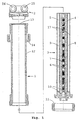
- FIG. 1 A preferred embodiment of the Electrolysis device for operation with direct current is shown in Figure 1 in longitudinal section, for better The housing 1, the connection head 2 and the interchangeable cartridge 3 are shown individually.
- Figure 1 shows an exchangeable cartridge 3 with a Chamber 4 for the untreated aqueous solution, one Chamber 5 for the treated aqueous solution and an electrode chamber, in the two graphite electrodes 6 and a bipolar Fixed bed electrode 7 made of electrically conductive and non-conductive particles are arranged and against the Chambers for the untreated or treated aqueous solution by means of a casing 8.9 with through openings is delimited in the form of small holes or slots.
- the electrodes 6 are connected to a power supply 10 control unit, not shown, connected at time intervals the polarity reversal of the electrodes is permitted and in turn connected to an electrical DC voltage source is.
- the cartridge 3 is - as by the arrow and the axis of the device drawn in as a broken line indicated - insert into housing 1 from below and attached with a union nut 11.
- the housing 1 is made essentially from a casing tube 12 and instructs at its other end a baffle 13 for shielding the electric field and an upward sliding union nut 14 with which the one inlet opening 15 for the untreated aqueous solution and an outlet opening 16 for the treated aqueous solution connection head 2 is attached to the housing 1.
- the cartridge 3 may preferably have an outer envelope 17 which the chambers 4,5 for the aqueous solution are sealed off from the outside. If there is no such sheathing 17, this takes over Jacket tube 12 this function.
- the casing tube 12 and the outer casing 17 of the cartridge 3 have the shape of a Cylinder on and preferably can also have the through openings provided envelopes 8.9 together at least have approximately the shape of a cylinder, wherein the chambers 4.5 for the untreated and the treated solution through partitions that are above or below the drawing level lie and between the wrappers 8.9 and the wrapper 17 and the casing tube 12 are arranged, separated from each other are.
- the device shown in Figure 1 is an aqueous Solution supplied via the inlet opening 15, so the solution from chamber 4 flows through the passage openings the sheath 8 in the electrode chamber flows in essentially parallel to the electric field through the fixed bed and flows through the openings after passing through the casing 9 via the chamber 5 and the outlet opening 16 from.
- Drinking water from the municipality of Mondsee was divided into two equal partial streams.
- a partial flow was through a reversible electrolysis device and then passed through a hot water boiler.
- the other Partial stream was directly by a without pretreatment Hot water boiler of the same type directed.
- PID controller for temperature control Proportional-integral-differential controller
- the tests were carried out at a DC voltage of 40 V and the polarity reversal takes place alternately after intervals of 30 or 45 seconds.
- the throughput at Drinking water was 500 l / h.
- the boiler temperature was in both boilers regulated to 70 ° C.
- both boilers were acidified with nitric acid and the amount of calcite separated in the boilers was determined.
- the drinking water used by the municipality of Mondsee has a total hardness of 16.5 ° dH, a carbonate hardness of 15.5 ° dH, an electrical conductivity of 530 ⁇ S / cm (25 ° C), a pH value of 7.5 (20 ° C) and an acid capacity up to pH 4.3 of 5.5 mmol / l.
- the following values are calculated from this according to DIN 38404-10: Design temperature 25 ° C 70 ° C Puff ceremoniessintenstician 0.86 mmol / l 1.09 mmol / l saturation index 0.46 0.83 Calcitsschtists pH 7.13 6.79 Calcitabscheidekapazmaschine 34.5 mg / l 74.87 mg / l
- the calcite separation capacity is approx. 75 mg / l.
- the test was carried out with drinking water from the municipality of Schriesheim (Germany).
- a volume flow of 1 m 3 / h was continuously passed through a reversible electrolysis device, as described in Example 1, and a partial flow of 20 l / h of the treated water was fed to a hot water boiler.
- the DC voltage applied to the electrolysis device was 35 V, and the polarity reversal took place alternately at intervals of 30 and 45 seconds.
- a blind path ie without pretreatment of the water, led a volume flow of likewise 20 l / h directly through a second hot water boiler.
- hot water boilers of the same type and heating coils of the same electrical power were installed in both sections.
- the boiler temperature was regulated to 80 ° C in both lines with identical controllers.
- the entire test duration was 21 days.
- the drinking water was examined before and after passing through the electrolysis device, whereby the following values were obtained: before treatment after treatment calcium 135 mg / l 134 mg / l magnesium 22.3 mg / l 22.7 mg / l sodium 21.3 mg / l 21.4 mg / l chloride 69 mg / l 69 mg / l sulfate 79.2 mg / l 77.7 mg / l nitrate 36.6 mg / l 36.6 mg / l pH value (20 ° C) 7.38 7.37 Conductivity (20 ° C) 109.2 mS / m 109.4 mS / m Acid capacity up to pH 4.3 5.36 mol / m 3 5.5 mol / m 3
Landscapes
- Chemical & Material Sciences (AREA)
- Water Supply & Treatment (AREA)
- Chemical Kinetics & Catalysis (AREA)
- General Chemical & Material Sciences (AREA)
- Life Sciences & Earth Sciences (AREA)
- Hydrology & Water Resources (AREA)
- Engineering & Computer Science (AREA)
- Electrochemistry (AREA)
- Organic Chemistry (AREA)
- Environmental & Geological Engineering (AREA)
- Water Treatment By Electricity Or Magnetism (AREA)
- Electrolytic Production Of Non-Metals, Compounds, Apparatuses Therefor (AREA)
- Electrolytic Production Of Metals (AREA)
- Lubricants (AREA)
- Crystals, And After-Treatments Of Crystals (AREA)
- Mechanical Treatment Of Semiconductor (AREA)
Applications Claiming Priority (5)
| Application Number | Priority Date | Filing Date | Title |
|---|---|---|---|
| CH250896 | 1996-10-15 | ||
| CH250896 | 1996-10-15 | ||
| CH181697 | 1997-07-29 | ||
| CH181697 | 1997-07-29 | ||
| PCT/IB1997/001243 WO1998016477A1 (de) | 1996-10-15 | 1997-10-08 | Verfahren zur reduzierung bzw. verhinderung der steinbildung |
Publications (2)
| Publication Number | Publication Date |
|---|---|
| EP0932583A1 EP0932583A1 (de) | 1999-08-04 |
| EP0932583B1 true EP0932583B1 (de) | 2003-07-09 |
Family
ID=25688754
Family Applications (1)
| Application Number | Title | Priority Date | Filing Date |
|---|---|---|---|
| EP97942143A Expired - Lifetime EP0932583B1 (de) | 1996-10-15 | 1997-10-08 | Verwendung einer elektrolysevorrichtung zur reduzierung bzw. verhinderung der steinbildung |
Country Status (9)
| Country | Link |
|---|---|
| US (1) | US6258250B1 (enExample) |
| EP (1) | EP0932583B1 (enExample) |
| JP (1) | JP3853372B2 (enExample) |
| CN (1) | CN1105082C (enExample) |
| AT (1) | ATE244686T1 (enExample) |
| AU (1) | AU728729B2 (enExample) |
| CA (1) | CA2268666C (enExample) |
| DE (1) | DE59710429D1 (enExample) |
| WO (1) | WO1998016477A1 (enExample) |
Cited By (1)
| Publication number | Priority date | Publication date | Assignee | Title |
|---|---|---|---|---|
| DE102012101031A1 (de) | 2012-02-08 | 2013-08-08 | Perma-Trade Wassertechnik Gmbh | Verfahren zur Vermeidung von Kalkansatz |
Families Citing this family (49)
| Publication number | Priority date | Publication date | Assignee | Title |
|---|---|---|---|---|
| US6130990A (en) * | 1998-08-25 | 2000-10-10 | Nestec S.A. | On-demand direct electrical resistance heating system and method thereof |
| DE19911875A1 (de) * | 1999-03-17 | 2000-09-28 | Judo Wasseraufbereitung | Vorrichtung zur elektrolytischen Behandlung von Wasser bzw. wässrigen Lösungen |
| IT1309792B1 (it) | 1999-04-22 | 2002-01-30 | Eltek Spa | Elettrodomestico utilizzante acqua, in particolare una macchinadi lavaggio, con dispositivo perfezionato per l'abbattimento |
| DE10030340C2 (de) * | 2000-06-28 | 2003-08-14 | Perma Trade Wassertechnik Gmbh | Vorrichtung zum Behandeln von Wasser |
| IL142984A0 (en) * | 2001-05-06 | 2002-04-21 | Scaletech Ltd | Apparatus and method for preventing scale formation in circulating water systems |
| FR2844783B1 (fr) * | 2002-05-07 | 2008-05-30 | Patrice Guy Noel Combe | Installation pour l'assainissement d'eau dont la frequence et la duree de fonctionnement sont reglables par un simple utilisateur |
| US7951176B2 (en) | 2003-05-30 | 2011-05-31 | Synthes Usa, Llc | Bone plate |
| US11259851B2 (en) | 2003-08-26 | 2022-03-01 | DePuy Synthes Products, Inc. | Bone plate |
| DE20321151U1 (de) | 2003-08-26 | 2006-09-07 | Synthes Gmbh | Knochenplatte |
| US8574268B2 (en) | 2004-01-26 | 2013-11-05 | DePuy Synthes Product, LLC | Highly-versatile variable-angle bone plate system |
| US11291484B2 (en) | 2004-01-26 | 2022-04-05 | DePuy Synthes Products, Inc. | Highly-versatile variable-angle bone plate system |
| US20080302651A1 (en) * | 2004-08-11 | 2008-12-11 | Miz Co., Ltd. | Performance Maintaining Method For Electrolyzed Functional Water Generating Apparatus |
| JP4919249B2 (ja) * | 2005-06-09 | 2012-04-18 | 株式会社竹中工務店 | 電気分解用複合電極及び電気分解槽 |
| DE102006005415A1 (de) * | 2006-02-03 | 2007-08-16 | Perma-Trade Wassertechnik Gmbh | Wasserbehandlungseinrichtung |
| US8187444B2 (en) * | 2007-08-10 | 2012-05-29 | Eric John Kruger | Fluid treatment device |
| US20110120870A1 (en) * | 2007-08-10 | 2011-05-26 | Eric John Kruger | Method and apparatus for treating a fluid |
| CN101381130B (zh) * | 2008-10-16 | 2013-05-01 | 宁波市镇海华泰电器厂 | 水处理设备及其自动换极电路 |
| EP2370725B1 (en) * | 2008-12-19 | 2016-04-06 | EPFF Electrical Pipe For Fluid transport AB | A pipe and a method for reducing biofilms |
| RU2437842C2 (ru) * | 2009-06-22 | 2011-12-27 | Ашот Папикович Хачатрян | Бездиафрагменный электролизер для активации продуктов и сред и устройство, включающее электролизер (варианты) |
| JP5146437B2 (ja) * | 2009-10-09 | 2013-02-20 | パナソニック株式会社 | 給湯機 |
| US20110192179A1 (en) * | 2010-02-05 | 2011-08-11 | Freije Iii William F | Evaporative heat transfer system and method |
| GB2491702B (en) * | 2010-03-30 | 2019-02-13 | Weatherford Tech Holdings Llc | A system and method for scale inhibition |
| US9447657B2 (en) * | 2010-03-30 | 2016-09-20 | The Lubrizol Corporation | System and method for scale inhibition |
| US9986600B2 (en) * | 2010-07-22 | 2018-05-29 | Koninklijke Philips N.V | Prevention or reduction of scaling on a heater element of a water heater |
| EP3257819B1 (en) | 2010-08-06 | 2019-10-02 | De Nora Holdings US, Inc. | Electrolytic on-site generator |
| US20120043223A1 (en) * | 2010-08-18 | 2012-02-23 | David Sherzer | Water treatment method |
| JP2012180538A (ja) * | 2011-02-28 | 2012-09-20 | Kurita Water Ind Ltd | 硫酸電解方法および硫酸電解装置 |
| CN104903249A (zh) * | 2012-04-02 | 2015-09-09 | 小利兰斯坦福大学 | 水灭菌装置和其用途 |
| CN102826662A (zh) * | 2012-09-10 | 2012-12-19 | 上海清里洁水处理科技有限公司 | 多通道高频脉冲水处理系统 |
| US20150284275A1 (en) * | 2014-04-02 | 2015-10-08 | Fredrick Billy Otieno Ongeche | Method and device for treating fouling in water systems |
| US20150284276A1 (en) * | 2014-04-02 | 2015-10-08 | Fredrick Billy Otieno Ongeche | Method and device for treating fouling in water systems |
| TWI551858B (zh) * | 2014-06-05 | 2016-10-01 | Solteam Opto Inc | Method for measuring the conductivity of conductor oxidation |
| CN105223236B (zh) * | 2014-06-18 | 2018-05-25 | 捷腾光电股份有限公司 | 减缓导体氧化的电导率量测方法 |
| JP6209256B1 (ja) * | 2016-07-21 | 2017-10-04 | 株式会社日本トリム | 電解水生成装置 |
| US10905476B2 (en) | 2016-09-08 | 2021-02-02 | DePuy Synthes Products, Inc. | Variable angle bone plate |
| US10624686B2 (en) | 2016-09-08 | 2020-04-21 | DePuy Synthes Products, Inc. | Variable angel bone plate |
| US10820930B2 (en) | 2016-09-08 | 2020-11-03 | DePuy Synthes Products, Inc. | Variable angle bone plate |
| US10800677B2 (en) | 2017-02-22 | 2020-10-13 | Ecowater Systems Llc | Electrolytic zinc dosing device and method for reducing scale |
| CN107245726A (zh) * | 2017-06-11 | 2017-10-13 | 王兆兵 | 一种高效自洁电解系统及其除垢方法 |
| CN107059046A (zh) * | 2017-06-11 | 2017-08-18 | 王兆兵 | 一种新型电解装置 |
| US11130691B2 (en) | 2017-12-22 | 2021-09-28 | Cabot Corporation | Anti-scaling composition for water systems |
| JP6988564B2 (ja) * | 2018-02-26 | 2022-01-05 | Toto株式会社 | 電解水吐水装置 |
| US11026727B2 (en) | 2018-03-20 | 2021-06-08 | DePuy Synthes Products, Inc. | Bone plate with form-fitting variable-angle locking hole |
| US10772665B2 (en) | 2018-03-29 | 2020-09-15 | DePuy Synthes Products, Inc. | Locking structures for affixing bone anchors to a bone plate, and related systems and methods |
| US11013541B2 (en) | 2018-04-30 | 2021-05-25 | DePuy Synthes Products, Inc. | Threaded locking structures for affixing bone anchors to a bone plate, and related systems and methods |
| US10925651B2 (en) | 2018-12-21 | 2021-02-23 | DePuy Synthes Products, Inc. | Implant having locking holes with collection cavity for shavings |
| CN109824118A (zh) * | 2019-03-27 | 2019-05-31 | 广州林科环保科技有限公司 | 一种板式吸附垢锈电极 |
| EP4097053A1 (en) | 2020-01-31 | 2022-12-07 | Cargill, Incorporated | Systems and methods for treatment of hard water |
| WO2025148994A1 (zh) * | 2024-01-10 | 2025-07-17 | 中国科学院理化技术研究所 | 一种有效抑制沉淀的直接电解海水制氢的方法 |
Family Cites Families (14)
| Publication number | Priority date | Publication date | Assignee | Title |
|---|---|---|---|---|
| GB1367883A (en) | 1970-09-28 | 1974-09-25 | Nat Res Dev | Electrochemical cells of the packed bed type |
| US3888756A (en) * | 1972-07-26 | 1975-06-10 | Stanley Electric Co Ltd | Apparatus for treating water containing impurities |
| DE2244244C3 (de) | 1972-09-15 | 1981-07-02 | Dart Industries Inc., 90048 Los Angeles, Calif. | Elektrolytische Verfahren zum Entfernen einer in einer wäßrigen verbrauchten Lösung gelösten verunreinigenden Substanz sowie dazu verwendbare regenerative elektrolytische Zelle |
| US3915822A (en) | 1974-05-22 | 1975-10-28 | Grace W R & Co | Electrochemical system with bed sections having variable gradient |
| US4176038A (en) * | 1974-07-11 | 1979-11-27 | Westinghouse Electric Corp. | Water purification method and apparatus |
| US4123339A (en) | 1975-02-07 | 1978-10-31 | Andco Industries, Inc. | Method and apparatus for electrochemical contaminant removal from liquid media |
| US4119518A (en) | 1975-07-16 | 1978-10-10 | Jorge Miller | Electrolytic cell for treatment of water |
| FR2547573B1 (fr) * | 1983-06-20 | 1988-05-06 | Meridional Oenologie Centre | Procede et dispositif de traitement des liquides aqueux, effluents industriels et agro-alimentaires, pour l'obtention d'eaux steriles ou potables et leur reutilisation ou recyclage |
| CH658238A5 (fr) * | 1984-07-10 | 1986-10-31 | Battelle Memorial Institute | Dispositif pour demineraliser de l'eau. |
| JPH033558A (ja) * | 1989-05-31 | 1991-01-09 | Ricoh Co Ltd | 画像読取装置の位置調整機構 |
| DE3922908A1 (de) * | 1989-07-12 | 1991-01-17 | Benckiser Wassertechnik Joh A | Verfahren und vorrichtung zur physikalischen behandlung von stroemendem hartem wasser |
| JPH0427491A (ja) * | 1990-05-24 | 1992-01-30 | Konica Corp | 固定床型複極式電解槽 |
| US5256268A (en) | 1990-07-18 | 1993-10-26 | Konica Corporation | Water treatment method and apparatus |
| JP3206819B2 (ja) * | 1991-07-26 | 2001-09-10 | コニカ株式会社 | 被処理水の電気化学的処理方法 |
-
1997
- 1997-10-08 DE DE59710429T patent/DE59710429D1/de not_active Expired - Fee Related
- 1997-10-08 EP EP97942143A patent/EP0932583B1/de not_active Expired - Lifetime
- 1997-10-08 WO PCT/IB1997/001243 patent/WO1998016477A1/de not_active Ceased
- 1997-10-08 US US09/284,441 patent/US6258250B1/en not_active Expired - Fee Related
- 1997-10-08 CA CA002268666A patent/CA2268666C/en not_active Expired - Fee Related
- 1997-10-08 JP JP51813598A patent/JP3853372B2/ja not_active Expired - Fee Related
- 1997-10-08 CN CN97198863A patent/CN1105082C/zh not_active Expired - Fee Related
- 1997-10-08 AT AT97942143T patent/ATE244686T1/de not_active IP Right Cessation
- 1997-10-08 AU AU43935/97A patent/AU728729B2/en not_active Ceased
Cited By (2)
| Publication number | Priority date | Publication date | Assignee | Title |
|---|---|---|---|---|
| DE102012101031A1 (de) | 2012-02-08 | 2013-08-08 | Perma-Trade Wassertechnik Gmbh | Verfahren zur Vermeidung von Kalkansatz |
| DE102012101031B4 (de) | 2012-02-08 | 2019-02-14 | Perma-Trade Wassertechnik Gmbh | Verfahren zur Vermeidung von Kalkansatz |
Also Published As
| Publication number | Publication date |
|---|---|
| EP0932583A1 (de) | 1999-08-04 |
| US6258250B1 (en) | 2001-07-10 |
| AU4393597A (en) | 1998-05-11 |
| ATE244686T1 (de) | 2003-07-15 |
| JP3853372B2 (ja) | 2006-12-06 |
| DE59710429D1 (de) | 2003-08-14 |
| JP2001502229A (ja) | 2001-02-20 |
| CN1233231A (zh) | 1999-10-27 |
| AU728729B2 (en) | 2001-01-18 |
| CN1105082C (zh) | 2003-04-09 |
| CA2268666C (en) | 2006-12-19 |
| WO1998016477A1 (de) | 1998-04-23 |
| CA2268666A1 (en) | 1998-04-23 |
Similar Documents
| Publication | Publication Date | Title |
|---|---|---|
| EP0932583B1 (de) | Verwendung einer elektrolysevorrichtung zur reduzierung bzw. verhinderung der steinbildung | |
| DE60017104T2 (de) | Wasserreinigungsverfahren | |
| DE3221253A1 (de) | Elektrolytischer chlorgasgenerator | |
| DE1792117A1 (de) | Verfahren und Vorrichtung zum Abtrennen von Ionen aus einer Loesung | |
| DE2337355A1 (de) | Vorrichtung und verfahren zur behandlung von verunreinigungen enthaltendem wasser | |
| DE2634007A1 (de) | Verfahren und vorrichtung zur ausfaellung von kolloiden aus waessrigen suspensionen | |
| DE60104211T2 (de) | Elektrochemische zelle und elektrochemische behandlung von kontaminiertem wasser | |
| EP0862538B1 (de) | Verfahren und vorrichtung zur behandlung von mit mikroorganismen und/oder schadstoffen belastetem wasser | |
| DE112005002782B4 (de) | Dielektrikum-Qualitätssteuervorrichtung und Funkenerosions-Bearbeitungsvorrichtung | |
| DE2218121A1 (de) | Verfahren zur Herabsetzung des Phenolgehaltes einer Lösung | |
| DE602004008584T2 (de) | Verfahren und vorrichtung zur elektrochemischen wasserdesinfektion | |
| DE2356845B2 (de) | Vorrichtung zur Desinfektion und Oxydation von Abwasser | |
| DE3409118C2 (de) | Verfahren zur Aufkonzentrierung einer verdünnten, wäßrigen Alkalihydroxidlösung durch Elektrolyse | |
| DE102012101031B4 (de) | Verfahren zur Vermeidung von Kalkansatz | |
| DE2439477A1 (de) | Verfahren zur behandlung eines industriellen abwassers | |
| DE2218124A1 (de) | Verfahren zur Verringerung des Metallgehaltes einer Lösung | |
| DE4329272C1 (de) | Vorrichtung zur Reinigung von Schmutzwässern | |
| DE2261744A1 (de) | Verfahren zur elektrolytischen behandlung von schmutzwasser | |
| DE2226324C3 (de) | Verfahren zur Reinigung von Leitungswasser | |
| DE2122745A1 (enExample) | ||
| DE4235833A1 (de) | Verfahren und Vorrichtung zur Wasserreinigung | |
| EP1858810B1 (de) | Vorrichtung und verfahren zur elektrolytischen behandlung von wasser beziehungsweise wässrigen lösungen | |
| AT138152B (de) | Verfahren zum Sterilisieren von Flüssigkeiten, insbesondere Trinkwasser, mittels Oligodynamie. | |
| EP1661863B1 (de) | Verfahren und Vorrichtung zur Aufbereitung und/oder Reinigung von Fluiden mit Wasserhärte | |
| DE102019122464A1 (de) | Elektrolysezelle |
Legal Events
| Date | Code | Title | Description |
|---|---|---|---|
| PUAI | Public reference made under article 153(3) epc to a published international application that has entered the european phase |
Free format text: ORIGINAL CODE: 0009012 |
|
| 17P | Request for examination filed |
Effective date: 19990412 |
|
| AK | Designated contracting states |
Kind code of ref document: A1 Designated state(s): AT BE CH DE DK ES FI FR GB GR IE IT LI LU MC NL PT SE |
|
| 17Q | First examination report despatched |
Effective date: 19991213 |
|
| RTI1 | Title (correction) |
Free format text: USE OF AN ELECTROLYTICAL APPARATUS TO REDUCE OR PREVENT SCALING |
|
| GRAG | Despatch of communication of intention to grant |
Free format text: ORIGINAL CODE: EPIDOS AGRA |
|
| RTI1 | Title (correction) |
Free format text: USE OF AN ELECTROLYTICAL APPARATUS TO REDUCE OR PREVENT SCALING |
|
| GRAG | Despatch of communication of intention to grant |
Free format text: ORIGINAL CODE: EPIDOS AGRA |
|
| GRAH | Despatch of communication of intention to grant a patent |
Free format text: ORIGINAL CODE: EPIDOS IGRA |
|
| GRAG | Despatch of communication of intention to grant |
Free format text: ORIGINAL CODE: EPIDOS AGRA |
|
| GRAH | Despatch of communication of intention to grant a patent |
Free format text: ORIGINAL CODE: EPIDOS IGRA |
|
| GRAA | (expected) grant |
Free format text: ORIGINAL CODE: 0009210 |
|
| AK | Designated contracting states |
Designated state(s): AT BE CH DE DK ES FI FR GB GR IE IT LI LU MC NL PT SE |
|
| PG25 | Lapsed in a contracting state [announced via postgrant information from national office to epo] |
Ref country code: NL Free format text: LAPSE BECAUSE OF FAILURE TO SUBMIT A TRANSLATION OF THE DESCRIPTION OR TO PAY THE FEE WITHIN THE PRESCRIBED TIME-LIMIT Effective date: 20030709 Ref country code: IE Free format text: LAPSE BECAUSE OF FAILURE TO SUBMIT A TRANSLATION OF THE DESCRIPTION OR TO PAY THE FEE WITHIN THE PRESCRIBED TIME-LIMIT Effective date: 20030709 Ref country code: FI Free format text: LAPSE BECAUSE OF FAILURE TO SUBMIT A TRANSLATION OF THE DESCRIPTION OR TO PAY THE FEE WITHIN THE PRESCRIBED TIME-LIMIT Effective date: 20030709 |
|
| REG | Reference to a national code |
Ref country code: GB Ref legal event code: FG4D Free format text: NOT ENGLISH |
|
| REG | Reference to a national code |
Ref country code: CH Ref legal event code: EP |
|
| REF | Corresponds to: |
Ref document number: 59710429 Country of ref document: DE Date of ref document: 20030814 Kind code of ref document: P |
|
| REG | Reference to a national code |
Ref country code: IE Ref legal event code: FG4D Free format text: GERMAN |
|
| REG | Reference to a national code |
Ref country code: CH Ref legal event code: NV Representative=s name: A. BRAUN, BRAUN, HERITIER, ESCHMANN AG PATENTANWAE |
|
| PG25 | Lapsed in a contracting state [announced via postgrant information from national office to epo] |
Ref country code: LU Free format text: LAPSE BECAUSE OF NON-PAYMENT OF DUE FEES Effective date: 20031008 |
|
| PG25 | Lapsed in a contracting state [announced via postgrant information from national office to epo] |
Ref country code: SE Free format text: LAPSE BECAUSE OF FAILURE TO SUBMIT A TRANSLATION OF THE DESCRIPTION OR TO PAY THE FEE WITHIN THE PRESCRIBED TIME-LIMIT Effective date: 20031009 Ref country code: GR Free format text: LAPSE BECAUSE OF FAILURE TO SUBMIT A TRANSLATION OF THE DESCRIPTION OR TO PAY THE FEE WITHIN THE PRESCRIBED TIME-LIMIT Effective date: 20031009 Ref country code: DK Free format text: LAPSE BECAUSE OF FAILURE TO SUBMIT A TRANSLATION OF THE DESCRIPTION OR TO PAY THE FEE WITHIN THE PRESCRIBED TIME-LIMIT Effective date: 20031009 |
|
| PG25 | Lapsed in a contracting state [announced via postgrant information from national office to epo] |
Ref country code: ES Free format text: LAPSE BECAUSE OF FAILURE TO SUBMIT A TRANSLATION OF THE DESCRIPTION OR TO PAY THE FEE WITHIN THE PRESCRIBED TIME-LIMIT Effective date: 20031020 |
|
| PG25 | Lapsed in a contracting state [announced via postgrant information from national office to epo] |
Ref country code: MC Free format text: LAPSE BECAUSE OF NON-PAYMENT OF DUE FEES Effective date: 20031031 Ref country code: BE Free format text: LAPSE BECAUSE OF NON-PAYMENT OF DUE FEES Effective date: 20031031 |
|
| GBT | Gb: translation of ep patent filed (gb section 77(6)(a)/1977) |
Effective date: 20031022 |
|
| NLV1 | Nl: lapsed or annulled due to failure to fulfill the requirements of art. 29p and 29m of the patents act | ||
| PG25 | Lapsed in a contracting state [announced via postgrant information from national office to epo] |
Ref country code: PT Free format text: LAPSE BECAUSE OF FAILURE TO SUBMIT A TRANSLATION OF THE DESCRIPTION OR TO PAY THE FEE WITHIN THE PRESCRIBED TIME-LIMIT Effective date: 20031209 |
|
| REG | Reference to a national code |
Ref country code: IE Ref legal event code: FD4D |
|
| BERE | Be: lapsed |
Owner name: *WEISSENBACHER ANDREAS Effective date: 20031031 |
|
| ET | Fr: translation filed | ||
| PLBE | No opposition filed within time limit |
Free format text: ORIGINAL CODE: 0009261 |
|
| STAA | Information on the status of an ep patent application or granted ep patent |
Free format text: STATUS: NO OPPOSITION FILED WITHIN TIME LIMIT |
|
| 26N | No opposition filed |
Effective date: 20040414 |
|
| PGFP | Annual fee paid to national office [announced via postgrant information from national office to epo] |
Ref country code: DE Payment date: 20071130 Year of fee payment: 11 |
|
| PGFP | Annual fee paid to national office [announced via postgrant information from national office to epo] |
Ref country code: AT Payment date: 20071011 Year of fee payment: 11 Ref country code: CH Payment date: 20071024 Year of fee payment: 11 Ref country code: IT Payment date: 20071029 Year of fee payment: 11 |
|
| PGFP | Annual fee paid to national office [announced via postgrant information from national office to epo] |
Ref country code: GB Payment date: 20071009 Year of fee payment: 11 Ref country code: FR Payment date: 20071029 Year of fee payment: 11 |
|
| REG | Reference to a national code |
Ref country code: CH Ref legal event code: PFA Owner name: WEISSENBACHER, ANDREAS Free format text: WEISSENBACHER, ANDREAS#WALTER-SIMMER-STRASSE 4#5310 MONDSEE (AT) -TRANSFER TO- WEISSENBACHER, ANDREAS#WALTER-SIMMER-STRASSE 4#5310 MONDSEE (AT) |
|
| REG | Reference to a national code |
Ref country code: CH Ref legal event code: PL |
|
| GBPC | Gb: european patent ceased through non-payment of renewal fee |
Effective date: 20081008 |
|
| REG | Reference to a national code |
Ref country code: FR Ref legal event code: ST Effective date: 20090630 |
|
| PG25 | Lapsed in a contracting state [announced via postgrant information from national office to epo] |
Ref country code: IT Free format text: LAPSE BECAUSE OF NON-PAYMENT OF DUE FEES Effective date: 20081008 Ref country code: DE Free format text: LAPSE BECAUSE OF NON-PAYMENT OF DUE FEES Effective date: 20090501 Ref country code: AT Free format text: LAPSE BECAUSE OF NON-PAYMENT OF DUE FEES Effective date: 20081008 |
|
| PG25 | Lapsed in a contracting state [announced via postgrant information from national office to epo] |
Ref country code: LI Free format text: LAPSE BECAUSE OF NON-PAYMENT OF DUE FEES Effective date: 20081031 Ref country code: FR Free format text: LAPSE BECAUSE OF NON-PAYMENT OF DUE FEES Effective date: 20081031 Ref country code: CH Free format text: LAPSE BECAUSE OF NON-PAYMENT OF DUE FEES Effective date: 20081031 |
|
| PG25 | Lapsed in a contracting state [announced via postgrant information from national office to epo] |
Ref country code: GB Free format text: LAPSE BECAUSE OF NON-PAYMENT OF DUE FEES Effective date: 20081008 |