EP0932125B1 - Vorrichtung mit einem aufschwenkbaren Flügel, insbesondere als Münzenaufnahmevorrichtung in einem selbstkassierenden Automaten ausgebildet - Google Patents
Vorrichtung mit einem aufschwenkbaren Flügel, insbesondere als Münzenaufnahmevorrichtung in einem selbstkassierenden Automaten ausgebildet Download PDFInfo
- Publication number
- EP0932125B1 EP0932125B1 EP98810049A EP98810049A EP0932125B1 EP 0932125 B1 EP0932125 B1 EP 0932125B1 EP 98810049 A EP98810049 A EP 98810049A EP 98810049 A EP98810049 A EP 98810049A EP 0932125 B1 EP0932125 B1 EP 0932125B1
- Authority
- EP
- European Patent Office
- Prior art keywords
- fixing
- base body
- slot
- retaining elements
- hinge
- Prior art date
- Legal status (The legal status is an assumption and is not a legal conclusion. Google has not performed a legal analysis and makes no representation as to the accuracy of the status listed.)
- Expired - Lifetime
Links
- 239000004033 plastic Substances 0.000 claims description 7
- 229920003023 plastic Polymers 0.000 claims description 7
- 238000003780 insertion Methods 0.000 claims description 5
- 230000037431 insertion Effects 0.000 claims description 5
- 239000000463 material Substances 0.000 claims description 5
- 238000012544 monitoring process Methods 0.000 claims description 3
- 229920000728 polyester Polymers 0.000 claims description 2
- 230000000694 effects Effects 0.000 claims 3
- 239000004952 Polyamide Substances 0.000 claims 1
- 229920002647 polyamide Polymers 0.000 claims 1
- 230000003019 stabilising effect Effects 0.000 claims 1
- 230000006378 damage Effects 0.000 description 5
- 238000013461 design Methods 0.000 description 4
- 238000000034 method Methods 0.000 description 4
- 230000008569 process Effects 0.000 description 4
- 229910000831 Steel Inorganic materials 0.000 description 3
- 230000008901 benefit Effects 0.000 description 3
- 238000010276 construction Methods 0.000 description 3
- 239000010959 steel Substances 0.000 description 3
- 238000007667 floating Methods 0.000 description 2
- 238000001746 injection moulding Methods 0.000 description 2
- 238000004519 manufacturing process Methods 0.000 description 2
- 230000005855 radiation Effects 0.000 description 2
- 239000000243 solution Substances 0.000 description 2
- 241000251468 Actinopterygii Species 0.000 description 1
- 241001295925 Gegenes Species 0.000 description 1
- 229920002302 Nylon 6,6 Polymers 0.000 description 1
- 230000009471 action Effects 0.000 description 1
- 238000013459 approach Methods 0.000 description 1
- 238000005452 bending Methods 0.000 description 1
- 230000015572 biosynthetic process Effects 0.000 description 1
- 210000000038 chest Anatomy 0.000 description 1
- 239000000945 filler Substances 0.000 description 1
- 238000002347 injection Methods 0.000 description 1
- 239000007924 injection Substances 0.000 description 1
- 230000007246 mechanism Effects 0.000 description 1
- 239000002184 metal Substances 0.000 description 1
- 230000008707 rearrangement Effects 0.000 description 1
- 238000005507 spraying Methods 0.000 description 1
- 238000003466 welding Methods 0.000 description 1
Images

Classifications
-
- G—PHYSICS
- G07—CHECKING-DEVICES
- G07F—COIN-FREED OR LIKE APPARATUS
- G07F9/00—Details other than those peculiar to special kinds or types of apparatus
- G07F9/06—Coin boxes
-
- E—FIXED CONSTRUCTIONS
- E05—LOCKS; KEYS; WINDOW OR DOOR FITTINGS; SAFES
- E05D—HINGES OR SUSPENSION DEVICES FOR DOORS, WINDOWS OR WINGS
- E05D7/00—Hinges or pivots of special construction
- E05D7/14—Hinges for safes
-
- E—FIXED CONSTRUCTIONS
- E05—LOCKS; KEYS; WINDOW OR DOOR FITTINGS; SAFES
- E05D—HINGES OR SUSPENSION DEVICES FOR DOORS, WINDOWS OR WINGS
- E05D5/00—Construction of single parts, e.g. the parts for attachment
- E05D5/02—Parts for attachment, e.g. flaps
-
- E—FIXED CONSTRUCTIONS
- E05—LOCKS; KEYS; WINDOW OR DOOR FITTINGS; SAFES
- E05D—HINGES OR SUSPENSION DEVICES FOR DOORS, WINDOWS OR WINGS
- E05D5/00—Construction of single parts, e.g. the parts for attachment
- E05D5/02—Parts for attachment, e.g. flaps
- E05D5/04—Flat flaps
-
- E—FIXED CONSTRUCTIONS
- E05—LOCKS; KEYS; WINDOW OR DOOR FITTINGS; SAFES
- E05D—HINGES OR SUSPENSION DEVICES FOR DOORS, WINDOWS OR WINGS
- E05D7/00—Hinges or pivots of special construction
- E05D7/12—Hinges or pivots of special construction to allow easy detachment of the hinge from the wing or the frame
-
- E—FIXED CONSTRUCTIONS
- E05—LOCKS; KEYS; WINDOW OR DOOR FITTINGS; SAFES
- E05Y—INDEXING SCHEME ASSOCIATED WITH SUBCLASSES E05D AND E05F, RELATING TO CONSTRUCTION ELEMENTS, ELECTRIC CONTROL, POWER SUPPLY, POWER SIGNAL OR TRANSMISSION, USER INTERFACES, MOUNTING OR COUPLING, DETAILS, ACCESSORIES, AUXILIARY OPERATIONS NOT OTHERWISE PROVIDED FOR, APPLICATION THEREOF
- E05Y2600/00—Mounting or coupling arrangements for elements provided for in this subclass
- E05Y2600/50—Mounting methods; Positioning
- E05Y2600/52—Toolless
- E05Y2600/53—Snapping
-
- E—FIXED CONSTRUCTIONS
- E05—LOCKS; KEYS; WINDOW OR DOOR FITTINGS; SAFES
- E05Y—INDEXING SCHEME ASSOCIATED WITH SUBCLASSES E05D AND E05F, RELATING TO CONSTRUCTION ELEMENTS, ELECTRIC CONTROL, POWER SUPPLY, POWER SIGNAL OR TRANSMISSION, USER INTERFACES, MOUNTING OR COUPLING, DETAILS, ACCESSORIES, AUXILIARY OPERATIONS NOT OTHERWISE PROVIDED FOR, APPLICATION THEREOF
- E05Y2999/00—Subject-matter not otherwise provided for in this subclass
Definitions
- the invention relates to a device according to the preamble of patent claim 1.
- This hinge strap also includes compact hinges with one in each Component to be attached pins provided.
- the known hinges are time consuming to be installed and generally not protected against unauthorized removal.
- a detachable "snap" hinge for attaching a door to a door frame shows for example, US 5,193,308 A.
- a hinge part is in a slot in the door frame inserted, causing snap elements in the door frame against a spring force be pressed outside. If the hinge part on the side wall of a Guide element abuts, openings in the hinge part are aligned such that the Spring elements penetrate them and hold the door securely.
- z. B. arranged on the door frame openings Pushing snap elements outwards with a tool and thus the wing of the Remove the hinge from the slot in the door frame. Can continue on the outside of the door frame markings are attached to holes at these locations to attach and the snap elements to the outside with a suitable tool Press to remove the hinge part from the bracket.
- German utility model DE 90 13 363 U shows a steel frame hinge construction, with the at any time even after installing the steel frame Hinge construction can be replaced without special assembly effort.
- the entire substructure is with a faceplate through the provided in the steel frame additional opening can be assembled and disassembled.
- the object of the invention is to provide a device with a base body and an To create a base body with a swivel-mounted wing, in which the swivel joint can be quickly assembled in a simple manner, but can no longer be removed without visible damage. Based on these Destruction is manipulation that occurs, for example, when unauthorized opening be made via the swivel joint, easily recognizable at any time.
- Another object of the invention is to provide a coin receiving device for a to create self-cashing machines, which are inexpensive considering necessary Security measures against unauthorized withdrawal of money can be established.
- Swivel joint preferably contributes to the inexpensive manufacture of a Coin receiving device taking the necessary safety precautions into account against unauthorized withdrawal of money.
- the swivel joint described here is suitable is excellent with a box-type coin receiving device, but can can also be used for devices that do not have any safety precautions against unauthorized removal of content.
- the swivel joint can be like a hinge strap be designed; but it can also compact designs be trained analogously.
- the invention uses snap-in holding elements which, like is described below, simply collapsible, but not without destruction are more solvable. This non-dismantling is an advantage everywhere where manipulations, such as money transport, should be immediately visible.
- the device according to the invention shown with a cross-section in FIG. 1 has a base body 1 , of which only the upper edge region 2 is drawn here, and a wing 5 which is arranged on the base body 1 with a swivel joint 3 and can be swung open.
- the device can be a coin receiving device as used in self-cashing machines.
- the wing 5 is designed here as a cover, which is also described below with its special features together with the coin receiving device.
- the swivel joint 3 is designed with a swivel axis 7 as a hinge band. On both sides of the pivot axis 7 , as can be seen in particular in FIG. 2 , a mounting flange 9 and 10 running parallel to the pivot axis 7 is arranged.
- the fastening flange 9 is snapped captively into a slot 11 in the rear long side of the cover 5 .
- the other mounting flange 10 is screwed into the upper edge region 2 of the rear side 16 of the base body 1 .
- the flange 9 has equally spaced slot-shaped recesses 17 which run perpendicular to the pivot axis 7 and which extend from its outer longitudinal side to the pivot axis 7 .
- the length of the recesses is selected such that the material part remaining in the flange 9 is sufficient for the flange stability.
- the width of the recesses 17 is selected such that they can be pushed in the slot 11 of the cover 5 via slot wall connections 19 .
- these diaphragm wall connections 19 are designed as connecting walls that run parallel to one another and are equally spaced from one another.
- the slot wall connections 19 serve to stabilize the slot 11 . They merely allow the slit wall areas to be "bent open” elastically to ensure the snap-in process described below, but do not allow an object to be inserted to bend up the slit wall areas and thus to open the "snap holder".
- the holding elements of the flange 9 are designed as openings 21a and 21b with a cuboidal contour and the associated web 23a and 23b , respectively.
- the hinge strap 3 shown in FIG. 2 as a separate component, for example an embodiment of the swivel joint, has three openings 21a and two openings 21b.
- the openings 21a and also the openings 21b each have the same distance from the outer longitudinal edge 22 of the flange 9 , but the distance between the openings 21a is smaller than that of the openings 21b.
- webs 25a and 25b are arranged at an analog distance from the openings 21a and 21b on one of the inner walls of the slot 11 in the cover, as can be seen in FIGS. 3 and 4 .
- Each of the webs 25a and 25b has an inclined inlet surface 27a and 27b and an inner web edge 29 that slopes perpendicularly to the inner wall 30 .
- This inner web edge 29 comes to rest on the inner web edge 31 of the webs 23a and 23b when the flange 9 is pushed into the slot 11 and snapped in, as shown in FIG .
- the flange 10 here has, for example, a width corresponding to the flange width of the flange 9 and four openings 33 designed as longitudinal holes. Through these openings 33 , screws, as shown in FIG. 1 for a single one, are inserted for fastening them to the upper rear edge region 2 of the base body 1 .
- the hexagon screw head 35 of each screw 34 rests in a projecting border 37 arranged on the outside of the edge region 2 .
- the border 37 is formed so narrow that the screw 34 is inserted forth from the outside and in an inserted screw 34, however, the screw head 35 is not longer rotatable, and no tool can be attached.
- the nuts 39 are then screwed onto the screws 34 for fastening the flange 10 .
- the attachment of the flange 10 is chosen to be unscrewable from the outside since the device is intended to serve as a coin receiving device, for example.
- the interior is protected by the cover 5 described below and its secured locking mechanism.
- This type of flange fastening makes unauthorized opening of the device more difficult: Unauthorized opening should in particular only be possible through mechanical destruction, which can then be recognized immediately. If no safety measures are necessary and the hinge should only be quick and easy to install, the special type of fastening just described with screwed-in screw heads can be dispensed with.
- the cover 5 is made of plastic and the hinge band 3 is made of metal.
- the flanges 9 of the hinge tape 3 thus have a material thickness of about one millimeter (a little more or a little less).
- the flange 9 is inserted into the slot 11 described above. I.e. in order to ensure a good hold, the slot 11 is also to be made approximately in this width of approximately one millimeter.
- the flange 9 could now be thickened by welding a band adapted to it, but this would require a considerable amount of work.
- a filler element 40 preferably injection molded from plastic, is placed on the flange 9 .
- This filling element 40 is shown inserted in FIG. 1 and is shown as a separate component in a top view in FIG. 5 and in FIG. 6 in an enlarged cross section along the line IV-IV in FIG .
- the filling element 40 has a hook-shaped support rail 41, the inner edge of which is placed on the outer longitudinal edge 22 of the flange 9 .
- the filling element 40 also has recesses 43 .
- the filling element 40 has two circular protruding knobs 45 , which are adapted to two circular openings 46 in the flange 9 .
- the thickness of the filling element 40 is adapted to an easily sprayable width of the slot 11 and the height of the width of the flange 9 .
- a material thinning 47 at the end opposite the support rail 41 only has its justification in the spraying process used.
- the filling element 40 is placed on the flange 9 in such a way that the knobs 45 lie in the openings 46 .
- the hinge tape 3 is then inserted together with the filling element 40 in direction A through the inner slot opening 49 .
- the support rail 41 of the filling element 40 together with the outer longitudinal edge 22 of the fastening flange 9 slide first over the inlet surfaces 27a and only then over the downstream inlet surfaces 27b. If both parts are fully inserted, the corresponding webs 25a and 25b lie in the openings 21a and 21b . Due to the sawtooth-shaped web design, subsequent removal is no longer possible. This above-mentioned reordering of the inlet surfaces 27a after the inlet surfaces 27b reduces the insertion force.
- sawtooth-shaped elevations 25a and 25b can also be used on both sides.
- Corresponding depressions can also be used instead of the openings 21a and 21b .
- the sawtooth-shaped elevations can also be arranged on the tab 9 and the depressions in the diaphragm wall 30 . In terms of production, however, it is easier to arrange the openings or depressions on the flange. Instead of holding only one flange with a snap connection, both flanges can also be held in this way.
- a coin receiving device is used wherever regularly filled Coin holders must be replaced by empty ones. The full containers become too brought to a control center, where it is then opened and emptied by authorized personnel become.
- the coin receiving device should be designed such that it manipulates opening resists during transportation. In particular, it should be prevented that the carrier has a portion of the coins stored on it can see personal enrichment.
- the coin holder must not necessarily resist raw use of violence, but everyone should Use of force to penetrate the coin contents to be clearly visible; the carrier is finally known and the monetary content is not so large that for the carrier would pay to go underground.
- the device designed as a coin receiving device is shown in a rear view with a view of the swivel joint 3 in FIG . It has a base body 1 , which only serves to hold the coins, and a pivotable cover 5, the pivotability of which is protected by the safety precautions described below.
- Base body 1 and cover 5 are made of plastic in an injection molding process. Particularly suitable plastic materials are so-called high-performance plastics with high rigidity and impact resistance, such as modified polyester. Good results have also been achieved with reinforced blended products, especially with polyamide 66, 61 and 12.
- the coin is entered through a closable opening 53 in the lid 5 .
- All the mechanical elements required for the closing process as well as all the electrical control, monitoring and / or device coding elements are arranged in the cover 5 .
- the base body 1 is only a passive container.
- the base body 1 has an upper groove-shaped edge 55 running around the front and the two side walls. The lower edge of the cover 5 engages in this groove 56 . Levering out or slightly bending the lid to "fish out” coins is therefore impossible without visible destruction.
- the cover 5 can be closed by a lock 57 arranged in it, designed as a cylinder lock, the cylinder (not shown) of which is connected to a lock bolt 59 .
- the locking bolt 59 engages in the closed position in a recess (not shown) in the front side wall of the base body 1.
- the coin filling opening 53 can be closed with a slide slide 63.
- the locking slide 63 has two guides with elongated holes 67a and 67b , in which guide pins 65a and 65b engage.
- a mechanical “flip-flop” element 69 is arranged to the left of the lock 57 .
- the mechanical "flip-flop” element 69 has an angle lever 71 which can be rotated about an axis 70 and which is under the action of a tension spring 72 . Depending on the position of the mechanical "flip-flop” element 69 , the tension spring 72 lies above or below the axis 70. The angle lever 71 is then held in the corresponding position by the tension spring 72 .
- the angle lever 71 has a pin 73 projecting parallel to the axis 70 and an extension 75.
- the extension 75 interacts with a free space 76, formed by a projecting angle piece 77 and a projecting web 79 .
- Angle piece 77 and web 79 are components of the closing slide 63.
- a manual rotary knob 81 which extends through the cover side wall 80 is coupled to both gearwheels 83a and 83b which are arranged adjacent to the cover inner side walls.
- the hand knob 81 can be replaced by a key switch to increase security.
- Both gear wheels 83a and 83b are connected by a shaft 85 which is preloaded with a torsion spring 86 .
- the gear 83a meshes with a rack 87 arranged on the locking slide 63.
- the gear 83b also meshes with a rack 89 which is arranged on a slide 91 displacing a bolt 90 .
- the latch 90 can be pushed transversely into a partial opening area of a bushing 93 which extends through the cover side wall 92 .
- a lever 97 In front of the inner bush opening 95 is a lever 97 which can be pivoted inwards against the force of a spring 96 .
- an electrical circuit board 99 is arranged, which is connected via a ribbon cable 100 to a floating connector 101 in the cover side wall 92 .
- the plug 101 is designed to be floating so that it can be inserted in a self-adjusting manner in a matching plug in the machine.
- the circuit board 99 carries an electronic coding for the coin receiving device in question for its identification.
- the circuit board 99 is also connected via a two-wire cable 102 to a switching relay 103 , which monitors the rotational position of the gear 83b .
- the rotational position of the gear wheel 83b indicates the position of the manual rotary knob 81 and thus also the closure or the open position of the coin filling opening as well as the release of the coin receiving device or its locking in the machine.
- the circuit board further 99ist by another cable 105 with the enlarged in Figure 9 shown MünzenEUR familiar 107 is connected.
- the coin counting device 107 has a radiation-emitting diode 109 on one side of the coin filling opening 53, a radiation deflecting prism 110 on the other side of the coin filling opening 53 and, in addition to the diode 109, a radiation detector 111.
- the two beams 113a and 113b crossing the opening 53 are spaced apart. The distance is chosen in such a way that even the smallest coin diameters interrupt at least one of the two beams so that each coin inserted is actually counted. From the number of coins dropped through the opening 53 , the degree of coin filling of the container 1 is inferred. An inaccuracy caused by coins of different cross-sections is accepted.
- a pin 115 (shown in broken lines) engages through the bushing 92 .
- the bolt 115 has a transverse slot 116 running perpendicular to its longitudinal axis through which the slide 91 engages.
- the coin receiving device is thereby fixed in the machine.
- the connector 101 is connected to an automatic connector (not shown).
- the slide valve 63 is displaced towards the circuit board 99 ; the coin fill opening 53 is open.
- the angle lever 71 lies with its extension 75 on the angle piece 77 .
- the hand rotary knob 81 is turned to the left, as a result of which the slide slide 63 is pushed in the direction of the swivel joint 3 (away from the circuit board 99 ) while closing the coin filling opening 53 .
- the extension 75 snaps into the free space 76 and rests on the web 70 and on the angle piece 77 .
- the slide 91 is pulled out of the notch of the bolt of the machine.
- the front edge of the lever 97 abuts an edge 114 of the slide 91 . Even by pushing an object into the socket 92 and pushing the lever 97 away, the coin filling opening 53 for "shaking out” coins cannot be opened.
- the locking bolt 59 is pivoted in the direction of the swivel joint 3 .
- the extension 75 of the mechanical “flip-flop” element 69 is brought out of the free space 76 .
- the lid 5 can be swung open and the coins can be removed from the container.
- the mechanical "flip-flop” element 69 is already in the correct position for the subsequent processes; it remains in this position even after the cover 5 has been closed . If the coin receiving device is inserted into the machine, the bolt which engages through the bushing 92 presses the lever 97 inwards, causing it to slide away from the edge 114 and release the slide 91 .
- the closing slide 63 and also the slide 91 are pushed in the direction of the circuit board 99 by the force of the tensioned torsion spring 86 via the gear wheels 83a and 83b and the toothed racks 87 and 89 .
- the coin filling opening 53 is opened again and the coin receiving device is locked with the bolt of the machine.
Landscapes
- Engineering & Computer Science (AREA)
- Mechanical Engineering (AREA)
- Physics & Mathematics (AREA)
- General Physics & Mathematics (AREA)
- Control Of Vending Devices And Auxiliary Devices For Vending Devices (AREA)
- Purses, Travelling Bags, Baskets, Or Suitcases (AREA)
Description
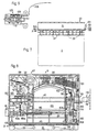
- Fig. 1
- einen Querschnitt durch das Schwenkgelenk der erfindungsgemässen Vorrichtung,
- Fig. 2
- eine Draufsicht auf das als Scharnierband ausgebildete Schwenkgelenk der in Figur 1 dargestellten Vorrichtung als separates Bauteil,
- Fig. 3
- einen Längsschnitt durch das Schwenkgelenk der in Figur 1 dargestellten Vorrichtung,
- Fig. 4
- einen Querschnitt durch einen als Deckel ausgebildeten mit dem Schwenkgelenk aufschwenkbaren gehaltenen Flügel der in Figur 1 dargestellten Vorrichtung,
- Fig. 5
- eine Draufsicht auf ein Füllelement als separates Bauteil des in Figur 1 dargestellten Schwenkgelenks,
- Fig. 6
- einen Querschnitt entlang der Linie VI - VI in Figur 5 des dort in vergrösserter Darstellung gezeigten Füllelements,
- Fig. 7
- eine Rückansicht der in Figur 1 dargestellten Vorrichtung, ausgebildet als Münzenaufnahmevorrichtung,
- Fig. 8
- eine Innenansicht eines Deckels der in Figur 7 dargestellten Münzenaufnahmevorrichtung und
- Fig. 9
- eine Ansicht gegen eine in der Deckelinnenseite angeordnete Münzeneinlaufkontrolle.
Claims (8)
- Vorrichtung mit einem Basiskörper (1) und einem am Basiskörper (1) mit einem Schwenkgelenk (3) aufschwenkbar angeordneten Flügel (5), wobei das Schwenkgelenk (3) zwei um die Schwenkachse (7) schwenkbare Befestigungsflansche (9, 10) zur Befestigung am Basiskörper (1) bzw. am Flügel (5) aufweist, wobei wenigstens einer der Befestigungsflansche (9, 10) einschnappende erste Halteelemente (21a, 21b) hat und ein Schlitz (11) für den Befestigungsflansch (9) an einer der zur Schwenkgelenkbefestigung vorgesehenen freien Randseite des Basiskörpers (1) und/oder des Flügels (5) sowie zweite, mit den ersten (21a, 21b) zusammenwirkende Halteelemente (25a, 25b) vorhanden sind, dadurch gekennzeichnet, dass die zweiten Halteelemente (25a, 25b) an einer der Innenwände (30) des Schlitzes (11) fest, als Teil der Innenwand angeordnet sind, damit der Befestigungsflansch (9) nach einem Befestigungszusammenschub unverlierbar und ohne Zerstörung nicht mehr lösbar mit der betreffenden Randseite verbindbar ist.
- Vorrichtung nach Anspruch 1, dadurch gekennzeichnet, dass beide Halteelemente wenigstens jeweils einen quer zur Befestigungseinschubrichtung verlaufenden Steg (23a, 23b, 25a, 25b) mit jeweils einer inneren Stegkante (29, 31) haben, wobei die Anordnung der Stege derart vorgenommen ist, dass nach einem Befestigungszusammenschub die einander zugeordneten inneren Stegkanten (29, 31) am Befestigungsflansch (9) und dem Randbereich bis auf eine Toleranz paarweise benachbart unlösbar zu liegen kommen.
- Vorrichtung nach Anspruch 2, gekennzeichnet durch mehrere erste und zweite Halteelemente (23a, 23b, 25a, 25b), deren paarweiser Abstand von der Schwenkachse (7) unterschiedlich ist, damit beim versuchsweisen Einschieben eines flachen Gegenstands zwischen ein Haltelelementpaar ein Demontieren des Schwenkgelenks (3) durch Öffnen sämtlicher eingeschnappter Haltelelementpaare nicht möglich ist.
- Vorrichtung nach einem der Ansprüche 1 bis 3, dadurch gekennzeichnet, dass die ersten oder die zweiten Halteelemente (25a, 25b) an der Innenwand (30) einer einen Schlitz (11) bildenden Doppelwand ausgebildet sind, wobei bevorzugt im Schlitzinnenraum (11) senkrecht zur Befestigungszusammenschubrichtung (A) distanzierte Schlitzseitenwandverbindungen (19) zur Stabilisierung der Schlitzbreite angeordnet sind und der betreffende Befestigungsflansch (9) zu den Schlitzseitenwandverbindungen angepasste Ausnehmungen (17) hat.
- Vorrichtung nach einem der Ansprüche 1 bis 4, dadurch gekennzeichnet, dass sie als austauschbare Münzenaufnahmevorrichtung eines selbstkassierenden Automaten ausgebildet ist und vorzugsweise einen die Münzen aufnehmenden Behälter als Basiskörper (1) und einen den Behälter mit einer Verschlusseinrichtung verschliessenden Deckel als Flügel (5) hat, wobei insbesondere sämtliche für den Schliessvorgang notwendigen bewegbaren mechanischen Elemente und vorzugsweise sämtliche elektrischen Regel-, Überwachungs- und/oder Vorrichtungscodierelemente im Deckel (5) angeordnet sind und der Behälter lediglich als passives Bauteil (1) ausgebildet ist.
- Vorrichtung nach Anspruch 5, dadurch gekennzeichnet, dass der Deckel (5) eine Münzeneinlasseinrichtung (53) mit einer Münzenzähleinrichtung (107) hat, damit anhand der gezählten Münzen auf einen Münzenfüllgrad des Behälters (1) geschlossen werden kann.
- Vorrichtung nach Anspruch 5 oder 6, gekennzeichnet durch wenigstens einen lediglich im Deckelrand (92) angeordneten elektrischen Stecker (101) zur Signalund/oder Energieübertragung für die elektrischen Regel-, Überwachungs- und/oder Vorrichtungscodierelemente (99).
- Vorrichtung nach einem der Ansprüche 5 bis 7, dadurch gekennzeichnet, dass der Behälter (1) und/oder der Deckel (5) aus Kunststoff, insbesondere aus einem modifizierten Polyester, bevorzugt einem Polyamid hergestellt sind.
Priority Applications (6)
| Application Number | Priority Date | Filing Date | Title |
|---|---|---|---|
| EP98810049A EP0932125B1 (de) | 1998-01-27 | 1998-01-27 | Vorrichtung mit einem aufschwenkbaren Flügel, insbesondere als Münzenaufnahmevorrichtung in einem selbstkassierenden Automaten ausgebildet |
| AT98810049T ATE237171T1 (de) | 1998-01-27 | 1998-01-27 | Vorrichtung mit einem aufschwenkbaren flügel, insbesondere als münzenaufnahmevorrichtung in einem selbstkassierenden automaten ausgebildet |
| DE59807857T DE59807857D1 (de) | 1998-01-27 | 1998-01-27 | Vorrichtung mit einem aufschwenkbaren Flügel, insbesondere als Münzenaufnahmevorrichtung in einem selbstkassierenden Automaten ausgebildet |
| DK98810049T DK0932125T3 (da) | 1998-01-27 | 1998-01-27 | Apparat med en drejelig vinge, især som møntopsamlingsapparat i en salgsautomat |
| AU12154/99A AU757243B2 (en) | 1998-01-27 | 1999-01-18 | Device with a swivelling wing, especially constructed as a coin-accepting device in a self-collecting vending machine |
| US09/237,797 US6264020B1 (en) | 1998-01-27 | 1999-01-27 | Device with a swivelling wing, especially constructed as a coin-accepting device in a self-collecting vending machine |
Applications Claiming Priority (1)
| Application Number | Priority Date | Filing Date | Title |
|---|---|---|---|
| EP98810049A EP0932125B1 (de) | 1998-01-27 | 1998-01-27 | Vorrichtung mit einem aufschwenkbaren Flügel, insbesondere als Münzenaufnahmevorrichtung in einem selbstkassierenden Automaten ausgebildet |
Publications (2)
| Publication Number | Publication Date |
|---|---|
| EP0932125A1 EP0932125A1 (de) | 1999-07-28 |
| EP0932125B1 true EP0932125B1 (de) | 2003-04-09 |
Family
ID=8235904
Family Applications (1)
| Application Number | Title | Priority Date | Filing Date |
|---|---|---|---|
| EP98810049A Expired - Lifetime EP0932125B1 (de) | 1998-01-27 | 1998-01-27 | Vorrichtung mit einem aufschwenkbaren Flügel, insbesondere als Münzenaufnahmevorrichtung in einem selbstkassierenden Automaten ausgebildet |
Country Status (6)
| Country | Link |
|---|---|
| US (1) | US6264020B1 (de) |
| EP (1) | EP0932125B1 (de) |
| AT (1) | ATE237171T1 (de) |
| AU (1) | AU757243B2 (de) |
| DE (1) | DE59807857D1 (de) |
| DK (1) | DK0932125T3 (de) |
Families Citing this family (3)
| Publication number | Priority date | Publication date | Assignee | Title |
|---|---|---|---|---|
| US6712352B2 (en) | 2000-10-17 | 2004-03-30 | Mars Incorporated | Lockable removable cassette |
| DE102008023244A1 (de) * | 2008-05-13 | 2009-11-19 | Wincor Nixdorf International Gmbh | Verfahren und Verwaltungssystem zur Überwachung von Entsorgungsvorgängen für Geldmittel |
| US10957445B2 (en) | 2017-10-05 | 2021-03-23 | Hill-Rom Services, Inc. | Caregiver and staff information system |
Family Cites Families (18)
| Publication number | Priority date | Publication date | Assignee | Title |
|---|---|---|---|---|
| DE209173C (de) * | ||||
| US699530A (en) * | 1901-01-28 | 1902-05-06 | Erskine H Jackson | Detachable fastener for hinges. |
| US864690A (en) * | 1907-01-04 | 1907-08-27 | Elmer E Rice | Hinge. |
| US908100A (en) * | 1908-05-07 | 1908-12-29 | Alfred J Howey | Hinge. |
| US909436A (en) * | 1908-07-24 | 1909-01-12 | John F Melton | Detachable hinge. |
| US1915448A (en) * | 1931-10-01 | 1933-06-27 | David C Ruth | Safety hinge |
| US1924537A (en) * | 1932-04-28 | 1933-08-29 | Bommer Emil | Spring hinge and adjustable leaf |
| GB398963A (en) * | 1932-05-31 | 1933-09-28 | Samuel Timings | Improvements in hinges |
| US3922048A (en) * | 1974-10-24 | 1975-11-25 | Whirlpool Co | Top lock and locator for appliance |
| FR2620759A1 (fr) * | 1987-09-17 | 1989-03-24 | Siguret Michel | Charniere demontable |
| DE3816016C2 (de) * | 1988-04-11 | 1997-07-24 | Landis & Gyr Betriebs Ag | Münzkassette |
| DE9013363U1 (de) * | 1990-09-21 | 1990-11-29 | Breuer & Schmitz, 5650 Solingen | Stahlzargen-Scharnierkonstruktion |
| US5193308A (en) * | 1992-07-22 | 1993-03-16 | The Stanley Works | Snap-in hinge for doors with hollow metal frames |
| US5557067A (en) * | 1993-07-22 | 1996-09-17 | Communications Technology Corporation | Pole mounted terminal housing |
| DE4431628A1 (de) * | 1994-09-06 | 1996-03-07 | Hollmann Gmbh & Co | Einbruchsicherung an Verkaufsautomaten |
| KR0121624Y1 (ko) * | 1995-04-06 | 1998-08-17 | 김광호 | 휴대용 노트북 컴퓨터의 힌지부재 |
| NO304158B1 (no) * | 1996-11-21 | 1998-11-02 | Grorud Ind As | Anordning ved en d°rhengselkonstruksjon av innsneppingstypen |
| KR100277591B1 (ko) * | 1997-09-29 | 2001-03-02 | 윤종용 | 냉장고 |
-
1998
- 1998-01-27 DE DE59807857T patent/DE59807857D1/de not_active Expired - Lifetime
- 1998-01-27 DK DK98810049T patent/DK0932125T3/da active
- 1998-01-27 AT AT98810049T patent/ATE237171T1/de active
- 1998-01-27 EP EP98810049A patent/EP0932125B1/de not_active Expired - Lifetime
-
1999
- 1999-01-18 AU AU12154/99A patent/AU757243B2/en not_active Ceased
- 1999-01-27 US US09/237,797 patent/US6264020B1/en not_active Expired - Lifetime
Also Published As
| Publication number | Publication date |
|---|---|
| AU757243B2 (en) | 2003-02-06 |
| US6264020B1 (en) | 2001-07-24 |
| EP0932125A1 (de) | 1999-07-28 |
| AU1215499A (en) | 1999-08-19 |
| DE59807857D1 (de) | 2003-05-15 |
| DK0932125T3 (da) | 2003-04-28 |
| ATE237171T1 (de) | 2003-04-15 |
Similar Documents
| Publication | Publication Date | Title |
|---|---|---|
| EP0677131B1 (de) | Verschlussvorrichtung für türen von gehäusen oder schränken | |
| DE69216988T2 (de) | Profilteil mit einem Griff und einer Vorrichtung zur Montage des Profilteils auf eine Tür, Tür mit einem solchen Profilteil und Kühlschrank mit zwei solchen Türen | |
| DE29923492U1 (de) | Scharnier | |
| EP0597170B1 (de) | Drehriegelverschluss | |
| EP0932125A1 (de) | Vorrichtung mit einem aufschwenkbaren Flügel, insbesondere als Münzenaufnahmevorrichtung in einem selbstkassierenden Automaten ausgebildet | |
| WO2005113923A1 (de) | Griffmulde | |
| DE60008223T2 (de) | Türbefestigungsvorrichtung | |
| EP0668420B1 (de) | Schliessblechkasten | |
| EP0341529A2 (de) | Schliessvorrichtung | |
| DE3602730C1 (en) | Distribution box for telecommunications cables | |
| DE3630406C2 (de) | ||
| EP3781766B1 (de) | Verschliessanordnung für einen schaltschrank und ein entsprechender adapter | |
| EP0735221A2 (de) | Bandseitensicherung für Türflügel | |
| EP0348790B1 (de) | Schublade od. dgl. mit mindestens einem verstellbaren Trennschied | |
| EP4146889B1 (de) | Scharnierverschluss | |
| DE102012101425B4 (de) | Drehgelenkverbindung | |
| DE29604643U1 (de) | Schaltschrank mit Rahmengestell und Tür mit Schubstangenverschluß | |
| DE19801681A1 (de) | Schließvorrichtung für Dachkoffer von Kraftfahrzeugen | |
| EP0976594A1 (de) | Laderaumtür | |
| DE19937889C1 (de) | Schaltschrank mit einem Schwenkrahmen | |
| EP0859899A1 (de) | Rechts und links verwendbares türschloss | |
| DE2833652C2 (de) | ||
| EP0945574B1 (de) | Band für Türen, Fenster oder dergleichen | |
| DE202023103333U1 (de) | Verriegelungsanordnung für einen Verteilerschrank | |
| DE4116379C2 (de) | Spardosenverschluß |
Legal Events
| Date | Code | Title | Description |
|---|---|---|---|
| PUAI | Public reference made under article 153(3) epc to a published international application that has entered the european phase |
Free format text: ORIGINAL CODE: 0009012 |
|
| AK | Designated contracting states |
Kind code of ref document: A1 Designated state(s): AT BE CH DE DK FR GB IT LI NL SE |
|
| AX | Request for extension of the european patent |
Free format text: AL;LT;LV;MK;RO;SI |
|
| 17P | Request for examination filed |
Effective date: 20000113 |
|
| AKX | Designation fees paid |
Free format text: AT BE CH DE DK FR GB IT LI NL SE |
|
| 17Q | First examination report despatched |
Effective date: 20010726 |
|
| GRAG | Despatch of communication of intention to grant |
Free format text: ORIGINAL CODE: EPIDOS AGRA |
|
| GRAG | Despatch of communication of intention to grant |
Free format text: ORIGINAL CODE: EPIDOS AGRA |
|
| GRAH | Despatch of communication of intention to grant a patent |
Free format text: ORIGINAL CODE: EPIDOS IGRA |
|
| GRAH | Despatch of communication of intention to grant a patent |
Free format text: ORIGINAL CODE: EPIDOS IGRA |
|
| GRAA | (expected) grant |
Free format text: ORIGINAL CODE: 0009210 |
|
| AK | Designated contracting states |
Designated state(s): AT BE CH DE DK FR GB IT LI NL SE |
|
| REG | Reference to a national code |
Ref country code: GB Ref legal event code: FG4D Free format text: NOT ENGLISH |
|
| REG | Reference to a national code |
Ref country code: SE Ref legal event code: TRGR Ref country code: CH Ref legal event code: EP |
|
| REG | Reference to a national code |
Ref country code: DK Ref legal event code: T3 |
|
| REG | Reference to a national code |
Ref country code: CH Ref legal event code: NV Representative=s name: KELLER & PARTNER PATENTANWAELTE AG |
|
| GBT | Gb: translation of ep patent filed (gb section 77(6)(a)/1977) | ||
| ET | Fr: translation filed | ||
| PG25 | Lapsed in a contracting state [announced via postgrant information from national office to epo] |
Ref country code: BE Free format text: LAPSE BECAUSE OF NON-PAYMENT OF DUE FEES Effective date: 20040131 |
|
| PLBE | No opposition filed within time limit |
Free format text: ORIGINAL CODE: 0009261 |
|
| STAA | Information on the status of an ep patent application or granted ep patent |
Free format text: STATUS: NO OPPOSITION FILED WITHIN TIME LIMIT |
|
| 26N | No opposition filed |
Effective date: 20040112 |
|
| BERE | Be: lapsed |
Owner name: *ASCOM AUTELCA A.G. Effective date: 20040131 |
|
| REG | Reference to a national code |
Ref country code: CH Ref legal event code: PUE Owner name: ASCOM (SCHWEIZ) AG Free format text: ASCOM AUTELCA AG#WORBSTRASSE 201#3073 GUEMLIGEN (CH) -TRANSFER TO- ASCOM (SCHWEIZ) AG#BELPSTRASSE 37#3000 BERN 14 (CH) Ref country code: CH Ref legal event code: PUE Owner name: ACS SOLUTIONS SCHWEIZ AG Free format text: ASCOM (SCHWEIZ) AG#BELPSTRASSE 37#3000 BERN 14 (CH) -TRANSFER TO- ACS SOLUTIONS SCHWEIZ AG#FRANKENSTRASSE 70#3018 BERN (CH) |
|
| REG | Reference to a national code |
Ref country code: GB Ref legal event code: 732E |
|
| REG | Reference to a national code |
Ref country code: GB Ref legal event code: 732E |
|
| REG | Reference to a national code |
Ref country code: FR Ref legal event code: TP |
|
| NLS | Nl: assignments of ep-patents |
Owner name: ACS SOLUTIONS SCHWEIZ AG Effective date: 20060822 Owner name: ASCOM (SCHWEIZ) AG Effective date: 20060822 |
|
| PG25 | Lapsed in a contracting state [announced via postgrant information from national office to epo] |
Ref country code: IT Free format text: LAPSE BECAUSE OF NON-PAYMENT OF DUE FEES Effective date: 20070127 |
|
| PGRI | Patent reinstated in contracting state [announced from national office to epo] |
Ref country code: IT Effective date: 20110616 |
|
| REG | Reference to a national code |
Ref country code: FR Ref legal event code: PLFP Year of fee payment: 18 |
|
| REG | Reference to a national code |
Ref country code: CH Ref legal event code: PCAR Free format text: NEW ADDRESS: EIGERSTRASSE 2 POSTFACH, 3000 BERN 14 (CH) |
|
| REG | Reference to a national code |
Ref country code: FR Ref legal event code: PLFP Year of fee payment: 19 |
|
| REG | Reference to a national code |
Ref country code: FR Ref legal event code: PLFP Year of fee payment: 20 |
|
| PGFP | Annual fee paid to national office [announced via postgrant information from national office to epo] |
Ref country code: GB Payment date: 20161228 Year of fee payment: 20 Ref country code: NL Payment date: 20161220 Year of fee payment: 20 Ref country code: CH Payment date: 20161223 Year of fee payment: 20 Ref country code: DK Payment date: 20161220 Year of fee payment: 20 |
|
| PGFP | Annual fee paid to national office [announced via postgrant information from national office to epo] |
Ref country code: FR Payment date: 20161221 Year of fee payment: 20 Ref country code: SE Payment date: 20161221 Year of fee payment: 20 |
|
| PGFP | Annual fee paid to national office [announced via postgrant information from national office to epo] |
Ref country code: DE Payment date: 20161219 Year of fee payment: 20 |
|
| PGFP | Annual fee paid to national office [announced via postgrant information from national office to epo] |
Ref country code: AT Payment date: 20161220 Year of fee payment: 20 |
|
| REG | Reference to a national code |
Ref country code: CH Ref legal event code: PFA Owner name: XEROX BUSINESS SERVICES (SWITZERLAND) AG, CH Free format text: FORMER OWNER: ACS SOLUTIONS SCHWEIZ AG, CH |
|
| PGFP | Annual fee paid to national office [announced via postgrant information from national office to epo] |
Ref country code: IT Payment date: 20170103 Year of fee payment: 20 |
|
| REG | Reference to a national code |
Ref country code: DE Ref legal event code: R082 Ref document number: 59807857 Country of ref document: DE Representative=s name: LENZING GERBER STUTE PARTNERSCHAFTSGESELLSCHAF, DE Ref country code: DE Ref legal event code: R081 Ref document number: 59807857 Country of ref document: DE Owner name: XEROX BUSINESS SERVICES (SWITZERLAND) AG, CH Free format text: FORMER OWNER: ACS SOLUTIONS SCHWEIZ AG, BERN, CH |
|
| REG | Reference to a national code |
Ref country code: DE Ref legal event code: R071 Ref document number: 59807857 Country of ref document: DE |
|
| REG | Reference to a national code |
Ref country code: DK Ref legal event code: EUP Effective date: 20180127 |
|
| REG | Reference to a national code |
Ref country code: CH Ref legal event code: PL Ref country code: NL Ref legal event code: MK Effective date: 20180126 |
|
| REG | Reference to a national code |
Ref country code: GB Ref legal event code: PE20 Expiry date: 20180126 |
|
| REG | Reference to a national code |
Ref country code: SE Ref legal event code: EUG |
|
| REG | Reference to a national code |
Ref country code: AT Ref legal event code: MK07 Ref document number: 237171 Country of ref document: AT Kind code of ref document: T Effective date: 20180127 |
|
| PG25 | Lapsed in a contracting state [announced via postgrant information from national office to epo] |
Ref country code: GB Free format text: LAPSE BECAUSE OF EXPIRATION OF PROTECTION Effective date: 20180126 |