EP0931450B1 - Vorrichtung zum Sortieren und Bündeln von Blumen - Google Patents
Vorrichtung zum Sortieren und Bündeln von Blumen Download PDFInfo
- Publication number
- EP0931450B1 EP0931450B1 EP99200913A EP99200913A EP0931450B1 EP 0931450 B1 EP0931450 B1 EP 0931450B1 EP 99200913 A EP99200913 A EP 99200913A EP 99200913 A EP99200913 A EP 99200913A EP 0931450 B1 EP0931450 B1 EP 0931450B1
- Authority
- EP
- European Patent Office
- Prior art keywords
- conveyor belt
- fork
- flowers
- shaped
- coupled
- Prior art date
- Legal status (The legal status is an assumption and is not a legal conclusion. Google has not performed a legal analysis and makes no representation as to the accuracy of the status listed.)
- Expired - Lifetime
Links
Images


Classifications
-
- A—HUMAN NECESSITIES
- A01—AGRICULTURE; FORESTRY; ANIMAL HUSBANDRY; HUNTING; TRAPPING; FISHING
- A01G—HORTICULTURE; CULTIVATION OF VEGETABLES, FLOWERS, RICE, FRUIT, VINES, HOPS OR SEAWEED; FORESTRY; WATERING
- A01G5/00—Floral handling
- A01G5/02—Apparatus for binding bouquets or wreaths
-
- A—HUMAN NECESSITIES
- A01—AGRICULTURE; FORESTRY; ANIMAL HUSBANDRY; HUNTING; TRAPPING; FISHING
- A01G—HORTICULTURE; CULTIVATION OF VEGETABLES, FLOWERS, RICE, FRUIT, VINES, HOPS OR SEAWEED; FORESTRY; WATERING
- A01G5/00—Floral handling
Definitions
- the invention relates to a device for sorting and bundling flowers, said device being provided with a frame and with a conveyor belt provided within said frame, which runs in a substantially horizontal plane during operation and to which supporting means are coupled so as to support the flowers, wherein said supporting means are capable of reciprocating movement in said substantially horizontal plane with respect to the conveyor belt in order to deliver the flowers to a second conveyor belt provided near a bundling statoin and running in a substantially vertical plane and wherein a plurality of fork-shaped means are coupled to said second conveyor belt so as to be pivotal about horizontal pivot axes.
- a device for sorting and bundling flowers being provided with a frame and with a conveyor belt provided within said frame, which runs in a substantially horizontal plane during operation and to which supporting means are coupled so as to support the flowers, wherein said supporting means are capable of reciprocating movement in said substantially horizontal plane with respect to the conveyor belt in order to deliver the flowers to a second conveyor belt provided near a bundling statoin and running in a substantially vertical plane and wherein
- weights are coupled to said pivotal fork-shaped means, in such a manner that said weights attempt to keep said fork-shaped means in a horizontal position.
- the device for sorting and bundling flowers comprises a frame (not shown), in which a few pulleys 2 are journalled, said pulleys being rotatable about vertical axes of rotation 1 ( Figure 3).
- the pulleys 2 function to guide a conveyor belt 3 which runs in a horizontal plane.
- the conveyor belt 3 may be a simple smooth belt 3, for example made of plastic material or rubber or the like material, which makes the construction a rather noiseless one.
- Supports 4 are secured to the conveyor belt in regularly spaced-apart relationship.
- the ends of two arms 7 and 8 are coupled to the supports 4 by means of vertically extending pivot pins 5 and 6.
- the ends of the arms 7 and 8 remote from the pivot pins 5 and 6 are coupled to a supporting means 11 by means of pivot pins 9 and 10 respectively extending parallel to the pivot pins 5 and 6, in which supporting means a slotted hole 12 is provided, said slotted hole being open at one end.
- the pivot pins 5, 6 and 9, 10 are located in the corner points of a parallelogram, as will be apparent in particular from Figures 1 and 3.
- the supporting means 11 are intended to support flowers 13, whereby every flower 13 can be suspended from a supporting means 11 by hand, by sliding the stem of the flower 13 into the slotted hole 12, in such a manner that the bud of the flower 13 will come to rest on top of the supporting means.
- control arms 14 and 15 including an obtuse angle with each other, whose purpose will be explained in more detail hereafter, are secured to each pivot pin 5.
- the endless conveyor belt 3 is driven in the direction according to arrow A.
- the flowers 13 are suspended from the supporting means 11 in a point located upstream of the pulley 2, to those supporting means 11 that are located near the upper part of the conveyor belt 3, seen in Figure 3.
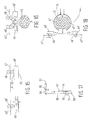
- a shaft 16 is provided near the pulley 2, said shaft being disposed at least substantially parallel to the axis of rotation 1 of said pulley 2 and being supported near its upper end by a tiltable journal 17 connected with the frame of the device, in such a manner that the shaft 16 is capable of pivoting movement near said journal 17, about an imaginary horizontal axis 18.
- the shaft 16 is furthermore journalled in a tiltable journal 19, in such a manner that also here the shaft 16 is capable of pivoting movement about an imaginary axis 20 with respect to the journal 19.
- Pulley 21 is secured to the shaft 16 between the ends of the shaft 16, said pulley 21 being coupled, by means of a crossed belt 22, to a pulley 23 secured to shaft 1, which rotates along with the pulley 2 during operation, therefore.
- a pulley 24 is secured to the bottom end of the shaft 16.
- a connecting means 28 is coupled between the ends of the arms 27 remote from the journals 17 and 19, said connecting means being capable of pivoting movement with respect to the arms 27, about axes 29 and 30 extending parallel to the axes 18 and 20, which, together with the axes 18 and 20, are located in the corner points of a parallelogram.
- a measuring vane 31 is secured to the bottom end of the lower arm 27, said measuring vane being located opposite a sensor 32 fixed to the frame.
- the stems of the flowers will move between the two pulleys 24 and 25 lying in one plane, as a result of which the pulley 24 will be pushed some distance away from the pulley 25, dependent on the thickness of the stem. It will be apparent that as a result of this also the distance between the measuring vane 31 and the sensor 32 will be changed, as a result of which the sensor will deliver a signal in accordance with the thickness of the stem.
- a number of sensors 33 are provided near the pulley 2, one sensor being located above the other, by means of which the length of the stem of a flower 13 is measured in a manner which is known per se.
- the measured thickness and/or length of the stem is used to programme a control mechanism of the device in such a manner, that each flower is delivered in a desired bundling station of a plurality of bundling stations arranged one behind the other along the conveyor belt 3, downstream of the pulley 2.
- an endless conveyor belt 34 running in a vertical plane is disposed at each bundling station, said conveyor belt being passed over two pulleys 35, which are rotatable about horizontal axes 36.
- the axes 36 extend at least substantially parallel to the longitudinal direction of the conveyor belt 3, whereby the conveyor belt 34 extends perpendicularly to the longitudinal direction of the conveyor belt 3.
- Regularly spaced-apart carriers 38 are secured to the conveyor belt 34.
- Horizontal axes 39 extending parallel to the pins 36 are journalled, in such manner as to be freely rotatable, in the ends of the carriers remote from the conveyor belt 34.
- a fork-shaped means 40 is secured to one end of each axis 39, said fork-shaped means being built up of two teeth 41 extending parallel to each other, whereby the free ends of said teeth remote from the pin 39 are slightly bent in a direction away from each other.
- a weight 42 is secured to the other end of each axis 39.
- the conveyor belt 34 will be driven in such a manner, that the upper part of the conveyor belt moves in a direction according to arrow B, seen in Figure 6. It will be apparent that when the movement of the fork-shaped means 40 effected as a result of the endless conveyor belt 34 being driven takes place, said fork-shaped means 40 will be kept in the horizontal position shown in Figure 6 at all times by the weights 42 secured to the axes 39, which project under the axes 39.
- a vertically adjustable stop or sorting pin 43 (Figure 2) is disposed some distance upstream of each conveyor belt 34 forming part of a bundling station, seen in the direction of movement of the endless conveyor belt 3 in the direction according to arrow A.
- the sorting pin 43 is thereby adjustable between a first position shown in Figure 2, in which the sorting pin lies in the path of the control arm 15, and a second position, in which the sorting pin 43 lies outside the path of the control arm 15.
- a number of further vertically adjustable stops or sorting pins 44 are arranged in regularly spaced-apart relationship near each conveyor belt 34, close to the conveyor belt 3. Furthermore a fixedly disposed sorting pint 45 is provided downstream of said four vertically adjustable sorting pins 44. The distance between said sorting pin 45 and the sorting pin 44 located closest to said sorting pin 45 is equal to the distance between the sorting pins 44 mutually.
- a guide wheel 46 is disposed some distance downstream of the fixedly disposed sorting pin 45.
- the sorting pin 43 or stop associated with said bundling station will be moved by means of the control mechanism of the device, from a position located outside the path of the control arm 15 to the position shown in Figure 2, which is located in the path of the control arm 15. Consequently the control arm 15 will strike the respective sorting pin 43 and be pivoted by means of the sorting pin 43, from the position illustrated in dotted lines in the centre of Figure 1 to the position shown in full lines in the present Figure.
- the flower 13 supported by a supporting means 11 thus extended is then moved in a path being in line with the opening between the legs 41 of a fork-shaped means 40 located nearest the conveyor belt 3, approximately in a plane through the two axes 36 of the endless conveyor belt 34, therefore, as is illustrated in Figure 6.
- the supporting means 11 is initially moved over the legs 41 of the respective fork-shaped means 40 thereby, so that the stem of the flower 13 in question is moved into the slot-shaped opening bounded by the legs 41 of the fork-shaped supporting means.
- control arm 14 will come into contact with the guide wheel 46, by means of which the arms 7 and 8 of the parallelogram mechanism supporting the supporting means 11 are caused to pivot back against the direction of movement of the conveyor belt 3, to a position in which the arms 7 and 8 extend at least substantially parallel to the longitudinal direction of the conveyor belt.
- the parallelogram mechanism is furthermore designed such that the arms can be pivoted from the extended position of the supporting means 11 with respect to the belt, in a direction opposed to the direction of movement of the belt during operation, the supporting means will be able to move out easily when said supporting means comes into contact with an obstacle of some kind, so that the risk of jamming and/or damage being caused to parts of the machine is prevented.
- the conveyor belt 34 will be moved one step in the direction according to arrow B, so that the fork-shaped means loaded with flowers will be moved out of the path of movement of flowers supported by extended supporting means 11, and an empty fork-shaped means is positioned in said path of movement so as to be filled with flowers again.
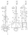
- the two carrier means 48 and 49 are secured to the upper ends of arms 51 and 52 respectively, which are pivotally connected to a frame part 55 near their bottom ends, by means of horizontal pivot axes 53 and 54 respectively.
- the arms 51 and 52 can thereby be pivoted towards or away from each other about the pivot pins 53 and 54 by means of a setting cylinder 56, as is indicated by means of arrows E and F.
- the frame part 55 is pivotally connected to the frame of the device by means of a pivot axis 57 extending perpendicularly to the pivot axes 53 and 54.
- the frame part 55 can thereby be pivoted about the pivot axis 57 with respect to the frame of the device by means of a setting cylinder 58, as is in particular diagrammatically illustrated in Figure 14.
- the rotatable disc 50 is journalled in the carrier means 49, in such a manner that said disc is capable of rotating movement with respect to the carrier means, about its axis extending parallel to the axes 53 and 54.
- the disc 50 is formed with an S-shaped passage 59, which is accessible from the outside of the disc 50 via an entrance aperture 60.
- the disc 50 is provided with teeth at its outer circumference, which teeth are in engagement with a chain 61 guided along part of the circumference of the disc 50.
- the chain 61 is furthermore guided along two guide wheels 62 supported by the carrier means 48 and is furthermore passed over a chain wheel 63, which is rotatable about the axis 54.
- the chain 61 can be moved to and fro, as is indicated by arrow G, by means of a setting cylinder 64 provided between the chain 61 and the arm 52.
- the construction is thereby such that on the outgoing stroke of the setting cylinder 64 the disc 50 will be rotated in anticlockwise direction, seen in Figure 13, about its axis of rotation a number of times, whilst the disc 50 will be rotated the same number of times in clockwise direction on the ingoing stroke of the setting cylinder 64.
- a lever 66 is coupled to the carrier means 48 by means of a axis 65 extending parallel to the axis of rotation of the disc 50.
- the end of the lever 66 located near the disc 50 is provided with a knife edge 67.
- the other end of the lever 66 is coupled to one end of a coupling rod 68, which is accommodated in a journal 69 secured to the arm 52 so as to be movable in its longitudinal direction.
- a chain wheel 71 which is rotatable about an axis of rotation 70 extending parallel to the pivot axis 54, is connected with the coupling rod 69 by means of a friction coupling.
- the binding string 47 When the carrier means 49 and 49' move towards each other, also the binding string 47 will be moved into the S-shaped passage 59 via the aperture 60, as is indicated in Figure 12. Thereupon the binding strings can be pulled tight around the stems of the flowers to be bunched, by driving the driven rollers 48 and 48' in such a manner, that the binding strings are moved in a direction according to arrows K and L respectively ( Figure 11).
- the setting cylinder 64 may be actuated, as a result of which the disc 50 is rotated and the parts of the binding strings located near said disc 50, in the S-shaped passage 59, are twisted together so as to attach said binding strings together.
- the setting cylinder 64 will move back the chain 61 to the initial position shown in Figure 13. Also the disc 50 is thereby rotated back to the initial position shown in Figure 13. Furthermore the chain piece 74 will first carry back the chain wheel 71 and the rod 68 connected therewith to the initial position shown in Figure 13, whilst the chain piece 73 will pass the chain wheel 71 after reaching said initial position, whereby the chain wheel 71 will be rotated against the action of the friction coupling connected therewith.
- arms 51 and 52 will be pivoted back from the position in which the arms are pivoted together to the position shown in Figure 13.
- the grab means comprises two jaws 76 and 77, one jaw being located above the other, and two jaws 78 and 79, one jaw being located above the other.
- the jaws 76 and 77 are pivotally coupled to one end of a carrier 81 by means of a vertical axis 80.
- the jaws 78 and 79 are pivotally coupled to another end of the carrier 81 by means of a vertical pivot axis 82.
- the carrier 81 is connected to a piston rod 83, which is with one end secured to a piston 84, which is located in a cylinder housing 85 of a horizontally disposed setting cylinder 86.
- coupling rods 87 and 88 are pivotally coupled to the jaws 76, 77 and 78, 79 respectively at some distance from the pivot axes 80 and 82.
- the other ends of the coupling rods 87 and 88 are pivotally coupled to a sliding piece 89.
- the sliding piece 89 is capable of sliding movement along a frame part 90 supporting the setting cylinder 86, said frame part being secured to a horizontally extending shaft 91, which is journalled in a bush 92.
- the bush 92 is secured to vertical shaft 93, which is rotatably journalled in the frame.
- Two pusher rods 94 and 95 are located at the end of the frame part 90 remote from the shaft 91.
- the sliding piece 89 Upon telescoping of the setting cylinder 86, that is when the piston rod 83 moves from the position shown in Figure 20 to the left, seen in Figures 19 - 21, the sliding piece 89 will strike a stop means 96 at some point, which stop means is movable with respect to the frame part 90, in the direction of movement of the sliding piece 89, and which can be locked in a desired position.
- the stop 96 When the sliding piece 89 strikes the stop 96, the jaws 76, 77 and 78, 79 will pivot towards each other upon further movement of the piston rod to the left, seen in Figures 19 - 21, from the position shown in Figure 20 to the position shown in Figure 19, so that the jaws grab the stems of a bundled bunch of flowers under the flower buds.
- the stop 96 By adjusting the stop 96 the movement of the jaws towards each other may be varied, this in accordance with the thickness of the bunches to be handled.
- a chain wheel 96 is secured to the shaft 93.
- the chain wheel 96 is coupled to a further chain wheel 98 by means of a chain 97, said further chain wheel 98 being rotatable about a shaft 99 secured to the frame of the device.
- An arm 100 is secured to the chain wheel 98.
- a toothed belt transmission may be used.
- Coupled to the free end of the arm 100 is a piston rod 101 of a setting cylinder 102 secured to the frame of the device.
- a pin 103 extending transversely to the shaft 91 is secured to said shaft 91, said pin cooperating with a guide plate 104 secured to the frame.
- the free end of the pin 103 extends along a part of the guide plate 104 which extends concentrically about the axis of the shaft 93.
- the free end of the pin 103 moves into an opening 105 provided in the guide plate 104, said opening being configured such that upon further pivoting of the grab means 75 to its end position illustrated on the right in Figures 22 and 23 the pin 103 and with it the shaft 91 connected with the pin 103 is pivoted about its central axis through an angle of 90° within the bush 92.
- the bunch of flowers grabbed in vertical position by the grab means is thus moved to a horizontal position, for example above a discharge conveyor 106 or the like.
- the bunch of flowers can be delivered onto the discharge conveyor and be discharged.
Landscapes
- Life Sciences & Earth Sciences (AREA)
- Environmental Sciences (AREA)
- Basic Packing Technique (AREA)
- Specific Conveyance Elements (AREA)
- Sorting Of Articles (AREA)
- Peptides Or Proteins (AREA)
- Agricultural Chemicals And Associated Chemicals (AREA)
- Packaging Of Special Articles (AREA)
- Cultivation Of Plants (AREA)
Claims (6)
- Eine Vorrichtung zum Sortieren und Bündeln von Blumen (13), wobei die Vorrichtung mit einem Rahmen und mit einem in dem Rahmen vorgesehenen Transportband (3) versehen ist, welches im Betrieb in einer im wesentlichen horizontalen Ebene läuft und an welchem Stützeinrichtungen (11) zum Stützen der Blumen (13) gekoppelt sind, wobei sich die Stützeinrichtungen (11) in der im wesentlichen horizontalen Ebene bezüglich des Transportbands (3) hin und her bewegen können, um die Blumen (13) einem zweiten Transportband (34) zuzuführen, welches in der Nähe einer Bündelstation vorgesehen ist und in einer im wesentlichen senkrechten Ebene läuft, und wobei eine Mehrzahl gabelförmiger Einrichtungen (40) schwenkbar um horizontale Schwenkachsen (39) an das zweite Transportband gekoppelt sind, dadurch gekennzeichnet, daß Gewichte (42) derart an die schwenkbaren gabelförmigen Einrichtungen (40) gekoppelt sind, daß die Gewichte (42) versuchen, die gabelförmigen Einrichtungen (40) in einer horizontalen Position zu halten.
- Vorrichtung wie in Anspruch 1 beansprucht, wobei sich das zweite Transportband (34) im wesentlichen senkrecht zu dem ersten Transportband (3) erstreckt.
- Vorrichtung wie in Anspruch 1 oder 2 beansprucht, wobei eine gabelförmige Einrichtung (40) an dem Ende einer horizontalen Welle fixiert ist, welche in einer an dem zweiten Transportband befestigten Stützeinrichtung (38) drehbar gelagert ist.
- Vorrichtung wie in Anspruch 3 beansprucht, wobei an dem von der gabelförmigen Einrichtung entfernt gelegenen Ende der Welle (39) ein Gewicht (42) an der Welle (39) aufgehängt ist.
- Vorrichtung wie in einem der voranstehenden Ansprüche beansprucht, wobei sich eine gabelförmige Einrichtung (40) im wesentlichen parallel zu der Längsrichtung des ersten Transportbands erstreckt.
- Vorrichtung wie in einem der voranstehenden Ansprüche beansprucht, wobei eine Zuführeinrichtung (48, 48') zum Zuführen von zwei Bindfäden (47, 47') vorgesehen ist, wobei die Anordnung derart ist, daß die gabelförmige Einrichtung (40) die Blumen (13) zwischen den Bindfäden verlagern kann.
Applications Claiming Priority (3)
| Application Number | Priority Date | Filing Date | Title |
|---|---|---|---|
| NL9400067A NL9400067A (nl) | 1994-01-14 | 1994-01-14 | Inrichting voor het sorteren en bundelen van bloemen. |
| NL9400067 | 1994-03-29 | ||
| EP95200065A EP0672341B1 (de) | 1994-01-14 | 1995-01-12 | Vorrichtung zum Sortieren und Zusammenbinden von Blumen |
Related Parent Applications (1)
| Application Number | Title | Priority Date | Filing Date |
|---|---|---|---|
| EP95200065A Division EP0672341B1 (de) | 1994-01-14 | 1995-01-12 | Vorrichtung zum Sortieren und Zusammenbinden von Blumen |
Publications (3)
| Publication Number | Publication Date |
|---|---|
| EP0931450A2 EP0931450A2 (de) | 1999-07-28 |
| EP0931450A3 EP0931450A3 (de) | 2000-06-21 |
| EP0931450B1 true EP0931450B1 (de) | 2004-04-21 |
Family
ID=19863706
Family Applications (3)
| Application Number | Title | Priority Date | Filing Date |
|---|---|---|---|
| EP99200913A Expired - Lifetime EP0931450B1 (de) | 1994-01-14 | 1995-01-12 | Vorrichtung zum Sortieren und Bündeln von Blumen |
| EP99200912A Expired - Lifetime EP0930002B1 (de) | 1994-01-14 | 1995-01-12 | Vorrichtung zum Bündeln von Blumen |
| EP95200065A Expired - Lifetime EP0672341B1 (de) | 1994-01-14 | 1995-01-12 | Vorrichtung zum Sortieren und Zusammenbinden von Blumen |
Family Applications After (2)
| Application Number | Title | Priority Date | Filing Date |
|---|---|---|---|
| EP99200912A Expired - Lifetime EP0930002B1 (de) | 1994-01-14 | 1995-01-12 | Vorrichtung zum Bündeln von Blumen |
| EP95200065A Expired - Lifetime EP0672341B1 (de) | 1994-01-14 | 1995-01-12 | Vorrichtung zum Sortieren und Zusammenbinden von Blumen |
Country Status (4)
| Country | Link |
|---|---|
| EP (3) | EP0931450B1 (de) |
| AT (3) | ATE192015T1 (de) |
| DE (3) | DE69516447T2 (de) |
| NL (1) | NL9400067A (de) |
Families Citing this family (20)
| Publication number | Priority date | Publication date | Assignee | Title |
|---|---|---|---|---|
| NL1006029C2 (nl) * | 1997-05-12 | 1998-11-13 | Brinkman Bv | Transportstelsel voor het transporteren van rozen naar een sorteermachine. |
| NL1006435C2 (nl) * | 1997-06-30 | 1999-01-04 | Stichting Tuinbouwontwikkeling | Sorteerinrichting. |
| NL1007280C2 (nl) * | 1997-10-15 | 1999-04-19 | Jamafa Agricultural Machinery | Inrichting voor het sorteren van bloemen. |
| NL1009464C2 (nl) * | 1998-06-22 | 1999-12-27 | Hietkamp Advies B V | Groeperen van snijbloemen. |
| EP1201114B1 (de) * | 2000-10-25 | 2006-01-18 | FPS Food Processing Systems B.V. | Vorrichtung und Verfahren zum Transport und Sortieren von Blumen |
| IL146140A0 (en) | 2000-10-25 | 2002-07-25 | Food Processing Systems | Apparatus and method for transporting and sorting flowers |
| NL1017452C2 (nl) * | 2001-02-26 | 2002-08-27 | Germaco B V | Invoerstation voor de verwerking van bolbloemen. |
| NL1020320C2 (nl) * | 2001-05-07 | 2002-11-19 | Havatec B V | Werkwijze en inrichting voor het verwerken van bloemen en takken. |
| NL1018013C2 (nl) * | 2001-05-07 | 2002-11-08 | Havatec B V | Inrichting voor het verwerken van bloemen en takken. |
| NL1018581C2 (nl) * | 2001-07-19 | 2003-01-21 | Altech Logistiek B V | Houder voor een plant. |
| NL1018965C2 (nl) * | 2001-09-17 | 2003-03-25 | Altech Logistiek B V | Bloemenoverzetinrichting. |
| NL1019295C2 (nl) * | 2001-11-05 | 2003-05-07 | Havatec B V | Gerbera-verpakkingsmethode. |
| NL1022550C2 (nl) * | 2003-01-31 | 2004-08-05 | Havatec B V | Inrichting en werkwijze voor het verwerken van bloemen. |
| NL1022950C2 (nl) * | 2003-03-17 | 2004-04-22 | Altech Logistiek B V | Bloemenovergeefinrichting. |
| NL1022951C2 (nl) * | 2003-03-17 | 2004-04-22 | Altech Logistiek B V | Overbrenginrichting voor bloemen. |
| WO2012055819A2 (de) | 2010-10-27 | 2012-05-03 | Schuessler Tim | Verfahren zur automatisierten handhabung von schnittblumen |
| NL1039064C2 (nl) * | 2011-09-22 | 2013-03-25 | P H Ruigrok Kwekerij B V | Werkwijze voor het samenstellen van gemengde boeketten alsmede een samenstel daarvoor. |
| ITTV20120111A1 (it) * | 2012-06-11 | 2013-12-12 | Techmek S R L | Apparato per eseguire il trasferimento di vegetali da una struttura di prelievo ad una struttura di ricezione |
| NL2019256B1 (nl) * | 2017-07-17 | 2019-01-30 | Havatec B V | Werkwijze en inrichting voor het torderen van een bundel plantenstelen in een boeket |
| CN115416913B (zh) * | 2022-09-30 | 2024-04-12 | 征图新视(江苏)科技股份有限公司 | 鲜花扎梗装置 |
Family Cites Families (11)
| Publication number | Priority date | Publication date | Assignee | Title |
|---|---|---|---|---|
| DE1189779B (de) * | 1962-03-10 | 1965-03-25 | Werner Fleischhauer | Vorrichtung zum Binden von Blumen oder Pflanzen |
| US3659709A (en) * | 1970-03-23 | 1972-05-02 | Floral Grading Inc | Method and apparatus for sorting flowers |
| US3743092A (en) * | 1971-08-27 | 1973-07-03 | E Levinstein | Apparatus for sorting flowers according to length |
| NL7310250A (en) * | 1973-07-23 | 1975-01-27 | George Johannes Ferdinandus Bl | Cut flower sorting machine - transports past measuring stations transferring to auxiliary conveyors with bunching mechanisms |
| US4470241A (en) * | 1982-05-21 | 1984-09-11 | Salinas Valley Engineering & Manufacturing, Inc. | Apparatus for bunching, trimming, and banding vegetables |
| IL73653A (en) * | 1984-11-27 | 1985-11-29 | Israel State | Apparatus for sorting and bunching flowers and other agricultural produce |
| NL182444C (nl) * | 1985-01-29 | 1988-03-16 | Potveer Bv | Inrichting voor het verzamelen en naar een bindtoestel voeren van bossen snijbloemen. |
| EP0486545A1 (de) * | 1989-08-11 | 1992-05-27 | KLAPWIJK, Arie | Vorrichtung zum behandeln von schnittblumen, insbesondere rosen |
| NL9000731A (nl) * | 1990-03-28 | 1991-10-16 | Aweta Bv | Werkwijze en inrichting voor het sorteren en bundelen van bloemen. |
| NL9100099A (nl) * | 1991-01-22 | 1992-08-17 | Aweta Bv | Steeldikte meting. |
| NL9200894A (nl) * | 1992-05-20 | 1993-12-16 | Zuurbier Tech Innovatie B V | Bundelinrichting, bundelsamenstel en bundellijn voor stengeldelen. |
-
1994
- 1994-01-14 NL NL9400067A patent/NL9400067A/nl not_active Application Discontinuation
-
1995
- 1995-01-12 AT AT95200065T patent/ATE192015T1/de not_active IP Right Cessation
- 1995-01-12 DE DE69516447T patent/DE69516447T2/de not_active Expired - Fee Related
- 1995-01-12 EP EP99200913A patent/EP0931450B1/de not_active Expired - Lifetime
- 1995-01-12 DE DE69532930T patent/DE69532930D1/de not_active Expired - Lifetime
- 1995-01-12 EP EP99200912A patent/EP0930002B1/de not_active Expired - Lifetime
- 1995-01-12 EP EP95200065A patent/EP0672341B1/de not_active Expired - Lifetime
- 1995-01-12 DE DE69530238T patent/DE69530238T2/de not_active Expired - Fee Related
- 1995-01-12 AT AT99200912T patent/ATE235803T1/de not_active IP Right Cessation
- 1995-01-12 AT AT99200913T patent/ATE264608T1/de not_active IP Right Cessation
Also Published As
| Publication number | Publication date |
|---|---|
| EP0931450A2 (de) | 1999-07-28 |
| ATE192015T1 (de) | 2000-05-15 |
| ATE235803T1 (de) | 2003-04-15 |
| EP0672341A3 (de) | 1995-11-29 |
| EP0930002A2 (de) | 1999-07-21 |
| DE69516447D1 (de) | 2000-05-31 |
| EP0672341A2 (de) | 1995-09-20 |
| DE69532930D1 (de) | 2004-05-27 |
| DE69516447T2 (de) | 2000-10-12 |
| EP0930002A3 (de) | 2000-06-21 |
| DE69530238D1 (de) | 2003-05-08 |
| NL9400067A (nl) | 1995-08-01 |
| ATE264608T1 (de) | 2004-05-15 |
| DE69530238T2 (de) | 2004-01-29 |
| EP0930002B1 (de) | 2003-04-02 |
| EP0672341B1 (de) | 2000-04-26 |
| EP0931450A3 (de) | 2000-06-21 |
Similar Documents
| Publication | Publication Date | Title |
|---|---|---|
| EP0931450B1 (de) | Vorrichtung zum Sortieren und Bündeln von Blumen | |
| EP0098733B1 (de) | Verfahren zur Behandlung von Eiern | |
| AU647686B2 (en) | Apparatus for producing croissants with fillings | |
| US4646908A (en) | Apparatus for stacking packages in particular for wrapping installations using a strip of heat-shrinkable material | |
| EP0405626B1 (de) | Brotschneidevorrichtung | |
| JPH09165004A (ja) | ラツピングテーブルおよび廃物包装装置 | |
| US4776465A (en) | Egg processing system | |
| NL1012981C2 (nl) | Werkwijze en inrichting voor het bossen van bloemen. | |
| US6674037B2 (en) | Apparatus and method for transporting and sorting flowers | |
| US4176802A (en) | Apparatus for laying balls of stranded material into cups of a conveyor | |
| US4125986A (en) | Bagging apparatus | |
| US3845705A (en) | Vegetable orienting and crowning | |
| CH691806A5 (fr) | Transporteur. | |
| JPH09207907A (ja) | 結束機 | |
| CA3070219C (en) | Method and device for twisting a bundle of plant stems in a bouquet | |
| WO1991001628A1 (en) | Device for processing cut flowers, particularly roses | |
| US2949919A (en) | Tobacco treatment | |
| EP1363486B1 (de) | Zuführstation zur bearbeitung von zwiebelblumen | |
| US3430750A (en) | Rotary gripper transfer mechanism | |
| EP1247770B1 (de) | Vorrichtung zur Übertragung von Früchten von einem ersten Förderer auf einen zweiten, welcher rechtwinklig zu dem ersten angeordnet ist | |
| SU424550A1 (ru) | Линия для выработки хлебобулочных изделий на листах | |
| JPS5927236B2 (ja) | 自動選花機 | |
| JP3491966B2 (ja) | 接木装置 | |
| JPH1081309A (ja) | 花卉の結束装置および結束方法 | |
| JPH11171130A (ja) | 花卉の処理装置および処理方法 |
Legal Events
| Date | Code | Title | Description |
|---|---|---|---|
| PUAI | Public reference made under article 153(3) epc to a published international application that has entered the european phase |
Free format text: ORIGINAL CODE: 0009012 |
|
| AC | Divisional application: reference to earlier application |
Ref document number: 672341 Country of ref document: EP |
|
| AK | Designated contracting states |
Kind code of ref document: A2 Designated state(s): AT BE CH DE DK ES FR GB GR IE IT LI LU MC NL PT SE |
|
| PUAL | Search report despatched |
Free format text: ORIGINAL CODE: 0009013 |
|
| AK | Designated contracting states |
Kind code of ref document: A3 Designated state(s): AT BE CH DE DK ES FR GB GR IE IT LI LU MC NL PT SE |
|
| 17P | Request for examination filed |
Effective date: 20000711 |
|
| 17Q | First examination report despatched |
Effective date: 20020430 |
|
| GRAP | Despatch of communication of intention to grant a patent |
Free format text: ORIGINAL CODE: EPIDOSNIGR1 |
|
| DAX | Request for extension of the european patent (deleted) | ||
| GRAS | Grant fee paid |
Free format text: ORIGINAL CODE: EPIDOSNIGR3 |
|
| GRAA | (expected) grant |
Free format text: ORIGINAL CODE: 0009210 |
|
| AC | Divisional application: reference to earlier application |
Ref document number: 0672341 Country of ref document: EP Kind code of ref document: P |
|
| AK | Designated contracting states |
Kind code of ref document: B1 Designated state(s): AT BE CH DE DK ES FR GB GR IE IT LI LU MC NL PT SE |
|
| PG25 | Lapsed in a contracting state [announced via postgrant information from national office to epo] |
Ref country code: LI Free format text: LAPSE BECAUSE OF FAILURE TO SUBMIT A TRANSLATION OF THE DESCRIPTION OR TO PAY THE FEE WITHIN THE PRESCRIBED TIME-LIMIT Effective date: 20040421 Ref country code: IT Free format text: LAPSE BECAUSE OF FAILURE TO SUBMIT A TRANSLATION OF THE DESCRIPTION OR TO PAY THE FEE WITHIN THE PRESCRIBED TIME-LIMIT;WARNING: LAPSES OF ITALIAN PATENTS WITH EFFECTIVE DATE BEFORE 2007 MAY HAVE OCCURRED AT ANY TIME BEFORE 2007. THE CORRECT EFFECTIVE DATE MAY BE DIFFERENT FROM THE ONE RECORDED. Effective date: 20040421 Ref country code: FR Free format text: LAPSE BECAUSE OF FAILURE TO SUBMIT A TRANSLATION OF THE DESCRIPTION OR TO PAY THE FEE WITHIN THE PRESCRIBED TIME-LIMIT Effective date: 20040421 Ref country code: CH Free format text: LAPSE BECAUSE OF FAILURE TO SUBMIT A TRANSLATION OF THE DESCRIPTION OR TO PAY THE FEE WITHIN THE PRESCRIBED TIME-LIMIT Effective date: 20040421 Ref country code: BE Free format text: LAPSE BECAUSE OF FAILURE TO SUBMIT A TRANSLATION OF THE DESCRIPTION OR TO PAY THE FEE WITHIN THE PRESCRIBED TIME-LIMIT Effective date: 20040421 Ref country code: AT Free format text: LAPSE BECAUSE OF FAILURE TO SUBMIT A TRANSLATION OF THE DESCRIPTION OR TO PAY THE FEE WITHIN THE PRESCRIBED TIME-LIMIT Effective date: 20040421 |
|
| REG | Reference to a national code |
Ref country code: GB Ref legal event code: FG4D |
|
| REG | Reference to a national code |
Ref country code: CH Ref legal event code: EP |
|
| REG | Reference to a national code |
Ref country code: IE Ref legal event code: FG4D |
|
| REF | Corresponds to: |
Ref document number: 69532930 Country of ref document: DE Date of ref document: 20040527 Kind code of ref document: P |
|
| PG25 | Lapsed in a contracting state [announced via postgrant information from national office to epo] |
Ref country code: SE Free format text: LAPSE BECAUSE OF FAILURE TO SUBMIT A TRANSLATION OF THE DESCRIPTION OR TO PAY THE FEE WITHIN THE PRESCRIBED TIME-LIMIT Effective date: 20040721 Ref country code: GR Free format text: LAPSE BECAUSE OF FAILURE TO SUBMIT A TRANSLATION OF THE DESCRIPTION OR TO PAY THE FEE WITHIN THE PRESCRIBED TIME-LIMIT Effective date: 20040721 Ref country code: DK Free format text: LAPSE BECAUSE OF FAILURE TO SUBMIT A TRANSLATION OF THE DESCRIPTION OR TO PAY THE FEE WITHIN THE PRESCRIBED TIME-LIMIT Effective date: 20040721 |
|
| PG25 | Lapsed in a contracting state [announced via postgrant information from national office to epo] |
Ref country code: DE Free format text: LAPSE BECAUSE OF FAILURE TO SUBMIT A TRANSLATION OF THE DESCRIPTION OR TO PAY THE FEE WITHIN THE PRESCRIBED TIME-LIMIT Effective date: 20040722 |
|
| PG25 | Lapsed in a contracting state [announced via postgrant information from national office to epo] |
Ref country code: ES Free format text: LAPSE BECAUSE OF FAILURE TO SUBMIT A TRANSLATION OF THE DESCRIPTION OR TO PAY THE FEE WITHIN THE PRESCRIBED TIME-LIMIT Effective date: 20040801 |
|
| REG | Reference to a national code |
Ref country code: CH Ref legal event code: PL |
|
| PG25 | Lapsed in a contracting state [announced via postgrant information from national office to epo] |
Ref country code: LU Free format text: LAPSE BECAUSE OF NON-PAYMENT OF DUE FEES Effective date: 20050112 Ref country code: IE Free format text: LAPSE BECAUSE OF NON-PAYMENT OF DUE FEES Effective date: 20050112 Ref country code: GB Free format text: LAPSE BECAUSE OF NON-PAYMENT OF DUE FEES Effective date: 20050112 |
|
| PG25 | Lapsed in a contracting state [announced via postgrant information from national office to epo] |
Ref country code: MC Free format text: LAPSE BECAUSE OF NON-PAYMENT OF DUE FEES Effective date: 20050131 |
|
| PLBE | No opposition filed within time limit |
Free format text: ORIGINAL CODE: 0009261 |
|
| STAA | Information on the status of an ep patent application or granted ep patent |
Free format text: STATUS: NO OPPOSITION FILED WITHIN TIME LIMIT |
|
| EN | Fr: translation not filed | ||
| 26N | No opposition filed |
Effective date: 20050124 |
|
| GBPC | Gb: european patent ceased through non-payment of renewal fee |
Effective date: 20050112 |
|
| REG | Reference to a national code |
Ref country code: IE Ref legal event code: MM4A |
|
| PG25 | Lapsed in a contracting state [announced via postgrant information from national office to epo] |
Ref country code: PT Free format text: LAPSE BECAUSE OF NON-PAYMENT OF DUE FEES Effective date: 20040921 |
|
| NLS | Nl: assignments of ep-patents |
Owner name: SYLVIA ALEXANDRA JANSSEN Effective date: 20080701 Owner name: ELISABETH MARIA JANSSEN Effective date: 20080701 |
|
| PGFP | Annual fee paid to national office [announced via postgrant information from national office to epo] |
Ref country code: NL Payment date: 20090131 Year of fee payment: 15 |
|
| REG | Reference to a national code |
Ref country code: NL Ref legal event code: V1 Effective date: 20100801 |
|
| PG25 | Lapsed in a contracting state [announced via postgrant information from national office to epo] |
Ref country code: NL Free format text: LAPSE BECAUSE OF NON-PAYMENT OF DUE FEES Effective date: 20100801 |