EP0929136B1 - Poste de distribution d'énergie placée à un endroit (semi)publique pour alimenter un particulier ou une entreprise - Google Patents
Poste de distribution d'énergie placée à un endroit (semi)publique pour alimenter un particulier ou une entreprise Download PDFInfo
- Publication number
- EP0929136B1 EP0929136B1 EP98204440A EP98204440A EP0929136B1 EP 0929136 B1 EP0929136 B1 EP 0929136B1 EP 98204440 A EP98204440 A EP 98204440A EP 98204440 A EP98204440 A EP 98204440A EP 0929136 B1 EP0929136 B1 EP 0929136B1
- Authority
- EP
- European Patent Office
- Prior art keywords
- cover
- container
- power station
- pit box
- station according
- Prior art date
- Legal status (The legal status is an assumption and is not a legal conclusion. Google has not performed a legal analysis and makes no representation as to the accuracy of the status listed.)
- Expired - Lifetime
Links
Images

Classifications
-
- H—ELECTRICITY
- H02—GENERATION; CONVERSION OR DISTRIBUTION OF ELECTRIC POWER
- H02B—BOARDS, SUBSTATIONS OR SWITCHING ARRANGEMENTS FOR THE SUPPLY OR DISTRIBUTION OF ELECTRIC POWER
- H02B7/00—Enclosed substations, e.g. compact substations
- H02B7/06—Distribution substations, e.g. for urban network
- H02B7/08—Underground substations
-
- H—ELECTRICITY
- H02—GENERATION; CONVERSION OR DISTRIBUTION OF ELECTRIC POWER
- H02B—BOARDS, SUBSTATIONS OR SWITCHING ARRANGEMENTS FOR THE SUPPLY OR DISTRIBUTION OF ELECTRIC POWER
- H02B1/00—Frameworks, boards, panels, desks, casings; Details of substations or switching arrangements
- H02B1/26—Casings; Parts thereof or accessories therefor
- H02B1/50—Pedestal- or pad-mounted casings; Parts thereof or accessories therefor
- H02B1/505—Pedestal- or pad-mounted casings; Parts thereof or accessories therefor retractable installations
Definitions
- the invention relates to an energy distribution station, as defined in the first part of claim 1.
- Such an energy distribution station is in Document WO95 / 34113 (see in particular the implementation according to Fig. 6-8).
- the first cover forms the top wall of a station a corresponding recess in the second cover box movable upwards, in a vertical wall the sockets arranged sunk one above the other are.
- lids raised but also with closed lids can be between the top Edge of the pit housing and the peripheral edge of the second Lid and on the other hand between the edge of the recess in the second cover and the peripheral edge of the first cover (Rain) water flow into the pit housing, whereby the water through an opening in the bottom of the pit housing to be dissipated.
- a disadvantage of this known power distribution station is above all that the one containing the sockets Box in the extended use position susceptible to damage is and a cumbersome obstacle forms. Measures to ensure that the distribution station in sensitive areas, such as the sockets, too in the case of floods of the overshoot type or (extraordinary) high groundwater level kept water-free will not be shown.
- the invention has set itself the task of to create improved power distribution station which does not have the disadvantage mentioned and in particular also in Floods offer adequate protection.
- the container When the pit housing is full due to the base and / or rainwater, the container works like an air bell and the apparatus remains in the air bubble within the Bell out of contact with the water in the pit housing. It in this case it is proportional extensive and heavy bell, which only for periodic Maintenance of those to be protected by the air bell Equipment must be lifted out of the pit housing.
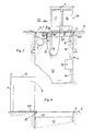
- the power distribution station has a recessed rectangular pit housing 1 from for example steel sheet treated against corrosion.
- the Pit housing 1 has a three along the top Sides extending channel profile 2, which on the fourth side (left in Fig. 1-3) on the space of the pit housing adjoined.
- the pit housing 1 is by means of two lids 3 and 4 lockable in the closed position with the road surface 5 (almost) lie on a common level.
- the cover 3 is designed to be hinged about an axis 3a, while the cover 4 in guide rails 6 between the closed position according to FIGS. 1 and 2 and the open 3 is movably guided.
- cross walls 7 formed a number of departments which can be closed overall by the cover 3. In these departments, those are for home use or operational use certain outlets 8 housed Service.
- the transverse walls 7 are at the top by means of a vertical connecting wall 9, which the departments from separates the remaining space 10 of the pit housing 1 with each other connected.
- the sockets 8 are separate or in groups normally - with lid 3 closed - open at the bottom and attached to the rest of closed containers 11.
- closed lid 3 (Fig. 1 and 3) are the containers 11 on the vertical wall 9 and the lid 3 is on the Top of the container 11 or. the top edges of the Partition walls 7.
- the containers 11 are independent of one another Axis 12 rotatably mounted, which is at a short distance from and provided parallel to the axis of rotation 3a of the cover 3 is.
- On the departments with containers 11 turned away pit wall is the so-called junction box 13 attached extendable upwards.
- This Junction box goes the stiff (5-wire) entering below Basic cable 14 in a flexible multi-core cable 15 over which to a box carried by the lid 4 16 leads in which under the management of the energy supplier vertical safety and measuring equipment housed is.
- the box 16 has a cable connection with the also carried by the cover 4 unit 17, which by means of a separate flexible cable 18 with the sockets 8 is connected. Within the unit 17, the over the different sockets 8 removed amounts of energy measured and registered.
- the boxes 16 and 17 are suspended from the lid 4 in a open at the bottom and closed at the rest Container 19 arranged, which container with the lid 4th can be moved up and down via the guide rail 6.
- the drawing shows the distribution station in the Situation in which the rainwater / groundwater within of the pit housing 1 to the level labeled 25 has risen.
- the socket 8 is in combination with a waterproof at the end of a consumer cable 24 attached connector 23 shown. 1 and 3 lies the connection point between socket and plug within the protective against the penetration of water Bubble.
- the lid 4 is normally in the closed position 1 and 2 by means of (not closer in the drawing locking means locked, which means 1 and 2 on the cover 4 can take up acting pressure.
- the container 19 is first, under which Influence of the above upward pressure, slightly from the room 10 of the pump housing move up while additional Lifting devices will be required around the container 19 to be able to lift completely (according to FIG. 3) out of the water.
- the one in the drawing with the rainwater / groundwater level 25 indicated state is a state in the generally will not occur for a long time.
- the level will be 25 (far) below the bottom of the container 19 lowered in the space 10 of the pit housing so that the container moves up and down slightly can be and tilted into the position shown in FIG. 4 can.
- Lids 3 and 4 and the support means designed for this difficult are around the load in the closed position to be able to record the traffic traveling over it. It plays an important role in lid support the channel profile designated 26.
Claims (6)
- Poste de distribution d'énergie destiné à être installé en renfoncement sur un terrain (semi) public pour le prélèvement de courant par des personnes privées ou par des entreprises, comportant un logement de fosse (1) devant être placé en renfoncement dans le sol et qui comporte un premier compartiment, qui peut être fermé par un premier couvercle (3) et comporte des prises femelles (8), et un compartiment pouvant être fermé par un second couvercle (4) et servant à loger une boíte de jonction (13) devant être raccordée à un câble souterrain (14), le second couvercle (4) possédant au moins une autre boíte (16, 17) devant être reliée par des câbles flexibles (15; 18) à la boíte de jonction (13) ou aux prises femelles (8), pour un appareillage de sécurité et de mesure, et dans lequel les prises femelles d'une part et le ou les coffrets pour l'appareil de sécurité et de mesure d'autre part peuvent être soulevées moyennant le soulèvement du premier couvercle (3) et du second couvercle (4) à partir des compartiments respectifs, caractérisé en ce que les prises femelles (8) sont disposées séparément ou par groupes et côte-à-côte dans des récipients (11) ouverts vers le bas et par ailleurs fermés, lesquels récipients sont reliés au premier couvercle (3) agencé sous la forme d'un couvercle rabattable, une fente étant présente, lorsque ce couvercle est dans la position fermée, entre le bord longitudinal libre du couvercle (3) et le bord supérieur voisin du boítier de fosse, fente dans laquelle un câble d'appareil d'utilisation, raccordé à une prise (8), peut ressortir à l'extérieur.
- Poste de distribution selon la revendication 1, caractérisé en ce que les récipients (11), qui contiennent les prises femelles (8) sont agencés de manière à être rabattables autour d'un axe (12) qui s'étend parallèlement à l'axe de rotation (3a) du couvercle considéré (3).
- Poste de distribution selon les revendications 1 et 2, caractérisé en ce que les récipients (11) sont séparés les uns des autres dans leur position abaissée dans le boítier de fosse (1), au moyen de parois transversales fixes (7).
- Poste de distribution selon les revendications 1-3, caractérisé en ce que les coffrets (16, 17) équipées de l'appareillage de sécurité et de mesure sont disposées également dans un récipient (19) ouvert vers le bas et par ailleurs fermé, lequel récipient (19) étant guidé avec possibilité de soulèvement et d'abaissement dans l'espace (10) du boítier de fosse (1) et peut être soulevé, en combinaison avec le second couvercle (4), jusqu'au-dessus du boítier de fosse (1).
- Poste de distribution selon la revendication 4, caractérisé en ce que le récipient (19), qui peut être soulevé et abaissé, pour les coffrets (16, 17) comportant un appareillage de sécurité et de mesure portent en bas, sur un côté, des déplacements de couplage (20), qui, lorsque le récipient (19) est dans sa position soulevée, attaquent un arbre (21) tourillonné le long du bord supérieur du logement en fosse (1) de telle sorte que le récipient (19) peut basculer autour de cet arbre (21) depuis sa position soulevée pour venir dans une position située à l'extérieur du boítier de fosse (1).
- Poste de distribution selon la revendication 5, caractérisé en ce que les boítes (16, 17) équipées de l'appareillage de sécurité et de mesure peuvent être ressorties, à la manière d'un tiroir, hors du récipient basculé (19).
Applications Claiming Priority (2)
| Application Number | Priority Date | Filing Date | Title |
|---|---|---|---|
| NL1007973 | 1998-01-07 | ||
| NL1007973A NL1007973C2 (nl) | 1998-01-07 | 1998-01-07 | Voor verzonken plaatsing op (semi) openbaar terrein bestemde voedingkast voor particuliere en/of bedrijfsmatige spanningafname. |
Publications (2)
| Publication Number | Publication Date |
|---|---|
| EP0929136A1 EP0929136A1 (fr) | 1999-07-14 |
| EP0929136B1 true EP0929136B1 (fr) | 2002-04-10 |
Family
ID=19766306
Family Applications (1)
| Application Number | Title | Priority Date | Filing Date |
|---|---|---|---|
| EP98204440A Expired - Lifetime EP0929136B1 (fr) | 1998-01-07 | 1998-12-23 | Poste de distribution d'énergie placée à un endroit (semi)publique pour alimenter un particulier ou une entreprise |
Country Status (6)
| Country | Link |
|---|---|
| EP (1) | EP0929136B1 (fr) |
| AT (1) | ATE216142T1 (fr) |
| DE (1) | DE59803718D1 (fr) |
| DK (1) | DK0929136T3 (fr) |
| ES (1) | ES2175605T3 (fr) |
| NL (1) | NL1007973C2 (fr) |
Cited By (1)
| Publication number | Priority date | Publication date | Assignee | Title |
|---|---|---|---|---|
| DE102009057437A1 (de) * | 2009-12-09 | 2011-06-16 | Sew-Eurodrive Gmbh & Co. Kg | Anordnung zum induktiven Beladen eines Energiespeichers Fahrzeugs und Ladestation |
Families Citing this family (12)
| Publication number | Priority date | Publication date | Assignee | Title |
|---|---|---|---|---|
| NL1021135C2 (nl) * | 2002-07-23 | 2004-01-27 | Odink & Koenderink Bv | Beschermkast voor elektronische en/of elektrotechnische apparatuur met water- en gasdichte kabelinvoer. |
| DE10314897B3 (de) * | 2003-04-01 | 2004-10-14 | Lic Langmatz Gmbh | System zur Unterbringung von Verteilereinrichtungen von Kupfer- und/oder Glasfaserkabeln |
| NL1025439C2 (nl) * | 2004-02-06 | 2005-08-09 | Seijsener Recreatietechniek B | Inrichting voor het verschaffen van faciliteiten aan nabij een aanlegsteiger gelegen vaartuigen. |
| EP1587199B1 (fr) * | 2004-04-16 | 2011-12-21 | Langmatz GmbH | Système de logement d'équipements de distribution de câbles à cuivre ou à fibres optiques |
| DE202010009603U1 (de) * | 2010-06-28 | 2010-11-11 | Kubik, Ralf | Wassergeschütztes Hochfahren und Absenken von Verteilungen in Unterflursystemen |
| DE102014017720B4 (de) * | 2014-12-02 | 2019-12-05 | Langmatz Gmbh | Unterflur-Anordnung von elektrischen und/oder elektronischen Einrichtungen insbesondere der Telekommunikation |
| NL2015564B1 (en) * | 2015-10-05 | 2017-05-17 | Brainwave B V | Underground power supply system, in particular an underground vehicle charging station and a method to charge an electric vehicle. |
| DE102016112613B4 (de) * | 2016-07-08 | 2019-06-27 | EnBW Energie Baden-Württemberg AG | Ladestation für Elektrofahrzeuge und Ladeanschluss für eine Ladestation |
| CN108819998A (zh) * | 2018-07-31 | 2018-11-16 | 国网河南省电力公司唐河县供电公司 | 一种小车式检修电源装置 |
| CN110611262B (zh) * | 2019-11-11 | 2020-11-13 | 新昌县佑资电力科技有限公司 | 一种下沉式防破坏电力配电柜 |
| CZ2022217A3 (cs) * | 2022-05-24 | 2023-07-05 | AŽD Praha s.r.o. | Bariérová studna |
| WO2024002505A1 (fr) * | 2022-06-29 | 2024-01-04 | Pierburg Gmbh | Dispositif de charge de bordure de trottoir ou de pavé pour charger un accumulateur d'énergie d'un véhicule à propulsion électrique |
Family Cites Families (2)
| Publication number | Priority date | Publication date | Assignee | Title |
|---|---|---|---|---|
| FR2721147B1 (fr) * | 1994-06-08 | 1996-07-19 | Philippe Lecreux | Unité de service technique. |
| DE29620779U1 (de) * | 1996-11-29 | 1997-02-06 | Moser Herbert | Senkelektrantanordnung |
-
1998
- 1998-01-07 NL NL1007973A patent/NL1007973C2/nl not_active IP Right Cessation
- 1998-12-23 EP EP98204440A patent/EP0929136B1/fr not_active Expired - Lifetime
- 1998-12-23 DK DK98204440T patent/DK0929136T3/da active
- 1998-12-23 ES ES98204440T patent/ES2175605T3/es not_active Expired - Lifetime
- 1998-12-23 DE DE59803718T patent/DE59803718D1/de not_active Expired - Fee Related
- 1998-12-23 AT AT98204440T patent/ATE216142T1/de not_active IP Right Cessation
Cited By (2)
| Publication number | Priority date | Publication date | Assignee | Title |
|---|---|---|---|---|
| DE102009057437A1 (de) * | 2009-12-09 | 2011-06-16 | Sew-Eurodrive Gmbh & Co. Kg | Anordnung zum induktiven Beladen eines Energiespeichers Fahrzeugs und Ladestation |
| DE102009057437B4 (de) | 2009-12-09 | 2023-03-16 | Sew-Eurodrive Gmbh & Co Kg | Anordnung zum induktiven Beladen eines Energiespeichers Fahrzeugs und Ladestation |
Also Published As
| Publication number | Publication date |
|---|---|
| EP0929136A1 (fr) | 1999-07-14 |
| ATE216142T1 (de) | 2002-04-15 |
| DK0929136T3 (da) | 2002-07-01 |
| NL1007973C2 (nl) | 1999-07-08 |
| ES2175605T3 (es) | 2002-11-16 |
| DE59803718D1 (de) | 2002-05-16 |
Similar Documents
| Publication | Publication Date | Title |
|---|---|---|
| EP0929136B1 (fr) | Poste de distribution d'énergie placée à un endroit (semi)publique pour alimenter un particulier ou une entreprise | |
| DE2953103C2 (fr) | ||
| DE3423184C2 (de) | Unterflurstation für Kabelverzweigereinrichtungen der Fernmeldetechnik | |
| DE2116402B2 (de) | Bodenanschlußeinrichtung für elektrische Unterflur-Installationen | |
| DE202018100726U1 (de) | Rinnensystem | |
| DE2116401C3 (de) | Bodenanschlußvorrichtung für elektrische Unterflur-Installationen | |
| DE1949694C3 (de) | Unterirdisch angeordneter Niederspannungsverteiler | |
| EP0905842B1 (fr) | Poste de distribution d'énergie placé à un endroit semi-publique pour alimenter un particulier ou une entreprise | |
| DE3038074A1 (de) | Gehaeuse mit einschub fuer geraete der elektrischen nachrichtentechnik | |
| DE102015117187A1 (de) | Vorrichtung zum Anschluss von Energieleitungen an einen Verbraucher | |
| DE2643201B2 (de) | Hubladerfahrgestell | |
| EP0982822B1 (fr) | Station de distribution d'électricité | |
| EP1587199B1 (fr) | Système de logement d'équipements de distribution de câbles à cuivre ou à fibres optiques | |
| DE29908863U1 (de) | Erschließungs-, Revisions- und Verteilerschacht mit Hausanschluß-Winkelplatte | |
| DE3011619C2 (de) | Schaltgeräteschrank für transportable Siganlanlagen | |
| DE102013012079B4 (de) | Vorrichtung zur Versorgung, insbesondere von Schiffen, mit elektrischer Energie und Verfahren zum Sichern einer derartigen Vorrichtung | |
| WO2012052001A1 (fr) | Colonne pour milieux | |
| DE1665678C3 (de) | BodenanschluBvorrichtung tür elektrische Unterflurinstallationen | |
| DE3740486C2 (fr) | ||
| DE19515960C1 (de) | Parkanlage für Kraftfahrzeuge | |
| DE3907412A1 (de) | Gehaeusesystem zur aufnahme von elektrischen einschueben | |
| DE19507377A1 (de) | Heizungskasten | |
| DE7223445U (de) | Schaltanlage | |
| DE7530099U (de) | Vorrichtung zur Deckenmontage von Elektrochirurgiegeräten und peroperativen Überwachungsgeräten | |
| EP0940898B1 (fr) | Coffre de connexion de câble dans un poste de distribution apte à être abaissé dans le sol |
Legal Events
| Date | Code | Title | Description |
|---|---|---|---|
| PUAI | Public reference made under article 153(3) epc to a published international application that has entered the european phase |
Free format text: ORIGINAL CODE: 0009012 |
|
| AK | Designated contracting states |
Kind code of ref document: A1 Designated state(s): AT BE CH DE DK ES FR GB IE IT LI LU MC NL |
|
| AX | Request for extension of the european patent |
Free format text: AL;LT;LV;MK;RO;SI |
|
| 17P | Request for examination filed |
Effective date: 19990630 |
|
| AKX | Designation fees paid |
Free format text: AT BE CH DE DK ES FR GB IE IT LI LU MC NL |
|
| GRAG | Despatch of communication of intention to grant |
Free format text: ORIGINAL CODE: EPIDOS AGRA |
|
| 17Q | First examination report despatched |
Effective date: 20010307 |
|
| GRAG | Despatch of communication of intention to grant |
Free format text: ORIGINAL CODE: EPIDOS AGRA |
|
| GRAG | Despatch of communication of intention to grant |
Free format text: ORIGINAL CODE: EPIDOS AGRA |
|
| GRAH | Despatch of communication of intention to grant a patent |
Free format text: ORIGINAL CODE: EPIDOS IGRA |
|
| GRAH | Despatch of communication of intention to grant a patent |
Free format text: ORIGINAL CODE: EPIDOS IGRA |
|
| REG | Reference to a national code |
Ref country code: GB Ref legal event code: IF02 |
|
| GRAA | (expected) grant |
Free format text: ORIGINAL CODE: 0009210 |
|
| AK | Designated contracting states |
Kind code of ref document: B1 Designated state(s): AT BE CH DE DK ES FR GB IE IT LI LU MC NL |
|
| REF | Corresponds to: |
Ref document number: 216142 Country of ref document: AT Date of ref document: 20020415 Kind code of ref document: T |
|
| REG | Reference to a national code |
Ref country code: CH Ref legal event code: EP |
|
| REG | Reference to a national code |
Ref country code: CH Ref legal event code: NV Representative=s name: FELBER & PARTNER AG PATENTANWAELTE Ref country code: IE Ref legal event code: FG4D Free format text: GERMAN |
|
| REF | Corresponds to: |
Ref document number: 59803718 Country of ref document: DE Date of ref document: 20020516 |
|
| REG | Reference to a national code |
Ref country code: DK Ref legal event code: T3 |
|
| GBT | Gb: translation of ep patent filed (gb section 77(6)(a)/1977) |
Effective date: 20020708 |
|
| ET | Fr: translation filed | ||
| REG | Reference to a national code |
Ref country code: ES Ref legal event code: FG2A Ref document number: 2175605 Country of ref document: ES Kind code of ref document: T3 |
|
| PLBE | No opposition filed within time limit |
Free format text: ORIGINAL CODE: 0009261 |
|
| STAA | Information on the status of an ep patent application or granted ep patent |
Free format text: STATUS: NO OPPOSITION FILED WITHIN TIME LIMIT |
|
| 26N | No opposition filed |
Effective date: 20030113 |
|
| PGFP | Annual fee paid to national office [announced via postgrant information from national office to epo] |
Ref country code: NL Payment date: 20041129 Year of fee payment: 7 |
|
| PGFP | Annual fee paid to national office [announced via postgrant information from national office to epo] |
Ref country code: MC Payment date: 20041201 Year of fee payment: 7 |
|
| PGFP | Annual fee paid to national office [announced via postgrant information from national office to epo] |
Ref country code: AT Payment date: 20041202 Year of fee payment: 7 |
|
| PGFP | Annual fee paid to national office [announced via postgrant information from national office to epo] |
Ref country code: IE Payment date: 20041222 Year of fee payment: 7 Ref country code: CH Payment date: 20041222 Year of fee payment: 7 |
|
| PGFP | Annual fee paid to national office [announced via postgrant information from national office to epo] |
Ref country code: LU Payment date: 20041227 Year of fee payment: 7 |
|
| PG25 | Lapsed in a contracting state [announced via postgrant information from national office to epo] |
Ref country code: IT Free format text: LAPSE BECAUSE OF NON-PAYMENT OF DUE FEES Effective date: 20051223 Ref country code: AT Free format text: LAPSE BECAUSE OF NON-PAYMENT OF DUE FEES Effective date: 20051223 |
|
| PG25 | Lapsed in a contracting state [announced via postgrant information from national office to epo] |
Ref country code: MC Free format text: LAPSE BECAUSE OF NON-PAYMENT OF DUE FEES Effective date: 20051231 Ref country code: LU Free format text: LAPSE BECAUSE OF NON-PAYMENT OF DUE FEES Effective date: 20051231 Ref country code: LI Free format text: LAPSE BECAUSE OF NON-PAYMENT OF DUE FEES Effective date: 20051231 Ref country code: CH Free format text: LAPSE BECAUSE OF NON-PAYMENT OF DUE FEES Effective date: 20051231 |
|
| PG25 | Lapsed in a contracting state [announced via postgrant information from national office to epo] |
Ref country code: NL Free format text: LAPSE BECAUSE OF NON-PAYMENT OF DUE FEES Effective date: 20060701 |
|
| REG | Reference to a national code |
Ref country code: CH Ref legal event code: PL |
|
| NLV4 | Nl: lapsed or anulled due to non-payment of the annual fee |
Effective date: 20060701 |
|
| REG | Reference to a national code |
Ref country code: IE Ref legal event code: MM4A |
|
| PGFP | Annual fee paid to national office [announced via postgrant information from national office to epo] |
Ref country code: DK Payment date: 20081230 Year of fee payment: 11 |
|
| PGFP | Annual fee paid to national office [announced via postgrant information from national office to epo] |
Ref country code: ES Payment date: 20081226 Year of fee payment: 11 |
|
| PGFP | Annual fee paid to national office [announced via postgrant information from national office to epo] |
Ref country code: DE Payment date: 20090202 Year of fee payment: 11 |
|
| PGFP | Annual fee paid to national office [announced via postgrant information from national office to epo] |
Ref country code: GB Payment date: 20081229 Year of fee payment: 11 |
|
| PGFP | Annual fee paid to national office [announced via postgrant information from national office to epo] |
Ref country code: BE Payment date: 20090202 Year of fee payment: 11 |
|
| PGFP | Annual fee paid to national office [announced via postgrant information from national office to epo] |
Ref country code: FR Payment date: 20081217 Year of fee payment: 11 |
|
| BERE | Be: lapsed |
Owner name: *ODINK & KOENDERINK B.V. Effective date: 20091231 |
|
| REG | Reference to a national code |
Ref country code: DK Ref legal event code: EBP |
|
| GBPC | Gb: european patent ceased through non-payment of renewal fee |
Effective date: 20091223 |
|
| REG | Reference to a national code |
Ref country code: FR Ref legal event code: ST Effective date: 20100831 |
|
| PG25 | Lapsed in a contracting state [announced via postgrant information from national office to epo] |
Ref country code: FR Free format text: LAPSE BECAUSE OF NON-PAYMENT OF DUE FEES Effective date: 20091231 Ref country code: BE Free format text: LAPSE BECAUSE OF NON-PAYMENT OF DUE FEES Effective date: 20091231 |
|
| PG25 | Lapsed in a contracting state [announced via postgrant information from national office to epo] |
Ref country code: DE Free format text: LAPSE BECAUSE OF NON-PAYMENT OF DUE FEES Effective date: 20100701 |
|
| PG25 | Lapsed in a contracting state [announced via postgrant information from national office to epo] |
Ref country code: GB Free format text: LAPSE BECAUSE OF NON-PAYMENT OF DUE FEES Effective date: 20091223 |
|
| PG25 | Lapsed in a contracting state [announced via postgrant information from national office to epo] |
Ref country code: DK Free format text: LAPSE BECAUSE OF NON-PAYMENT OF DUE FEES Effective date: 20100104 |
|
| REG | Reference to a national code |
Ref country code: ES Ref legal event code: FD2A Effective date: 20110309 |
|
| PG25 | Lapsed in a contracting state [announced via postgrant information from national office to epo] |
Ref country code: ES Free format text: LAPSE BECAUSE OF NON-PAYMENT OF DUE FEES Effective date: 20110308 |
|
| PG25 | Lapsed in a contracting state [announced via postgrant information from national office to epo] |
Ref country code: ES Free format text: LAPSE BECAUSE OF NON-PAYMENT OF DUE FEES Effective date: 20091224 |