EP1587199B1 - Système de logement d'équipements de distribution de câbles à cuivre ou à fibres optiques - Google Patents
Système de logement d'équipements de distribution de câbles à cuivre ou à fibres optiques Download PDFInfo
- Publication number
- EP1587199B1 EP1587199B1 EP04009054A EP04009054A EP1587199B1 EP 1587199 B1 EP1587199 B1 EP 1587199B1 EP 04009054 A EP04009054 A EP 04009054A EP 04009054 A EP04009054 A EP 04009054A EP 1587199 B1 EP1587199 B1 EP 1587199B1
- Authority
- EP
- European Patent Office
- Prior art keywords
- housing
- shaft
- distribution devices
- base plate
- water
- Prior art date
- Legal status (The legal status is an assumption and is not a legal conclusion. Google has not performed a legal analysis and makes no representation as to the accuracy of the status listed.)
- Expired - Lifetime
Links
- RYGMFSIKBFXOCR-UHFFFAOYSA-N Copper Chemical compound [Cu] RYGMFSIKBFXOCR-UHFFFAOYSA-N 0.000 title claims description 3
- 229910052802 copper Inorganic materials 0.000 title claims description 3
- 239000010949 copper Substances 0.000 title claims description 3
- 239000000835 fiber Substances 0.000 title description 5
- 238000009434 installation Methods 0.000 claims description 3
- 238000010276 construction Methods 0.000 claims 1
- 239000013307 optical fiber Substances 0.000 claims 1
- XLYOFNOQVPJJNP-UHFFFAOYSA-N water Substances O XLYOFNOQVPJJNP-UHFFFAOYSA-N 0.000 description 11
- 230000005540 biological transmission Effects 0.000 description 4
- 238000007789 sealing Methods 0.000 description 3
- 238000000034 method Methods 0.000 description 2
- 229910000831 Steel Inorganic materials 0.000 description 1
- 230000000712 assembly Effects 0.000 description 1
- 238000000429 assembly Methods 0.000 description 1
- 238000005452 bending Methods 0.000 description 1
- 230000001419 dependent effect Effects 0.000 description 1
- 238000005516 engineering process Methods 0.000 description 1
- 238000003780 insertion Methods 0.000 description 1
- 230000037431 insertion Effects 0.000 description 1
- 230000035515 penetration Effects 0.000 description 1
- 230000000284 resting effect Effects 0.000 description 1
- 239000002689 soil Substances 0.000 description 1
- 239000010959 steel Substances 0.000 description 1
Images


Classifications
-
- G—PHYSICS
- G02—OPTICS
- G02B—OPTICAL ELEMENTS, SYSTEMS OR APPARATUS
- G02B6/00—Light guides; Structural details of arrangements comprising light guides and other optical elements, e.g. couplings
- G02B6/46—Processes or apparatus adapted for installing or repairing optical fibres or optical cables
- G02B6/50—Underground or underwater installation; Installation through tubing, conduits or ducts
- G02B6/501—Underground or underwater installation; Installation through tubing, conduits or ducts underground installation of connection boxes
-
- H—ELECTRICITY
- H02—GENERATION; CONVERSION OR DISTRIBUTION OF ELECTRIC POWER
- H02G—INSTALLATION OF ELECTRIC CABLES OR LINES, OR OF COMBINED OPTICAL AND ELECTRIC CABLES OR LINES
- H02G9/00—Installations of electric cables or lines in or on the ground or water
- H02G9/10—Installations of electric cables or lines in or on the ground or water in cable chambers, e.g. in manhole or in handhole
Definitions
- the invention relates to a system for accommodating distributor devices for copper and / or fiber optic cables according to the preamble of patent claim 1.
- the DE 33 22 584 A1 discloses a system according to the preamble of claim 1.
- the housing containing the manifolds is folded out of the well for servicing purposes, with the cables being severely deflected, which can lead to the occurrence of bit errors in high bit rate transmissions.
- US-A 5,210,374 and DE 1952 453 U reveal airtight, bell-shaped housings which, for example, cover telephone lines and are embedded in the floor. They are not arranged in a shaft into which a mechanic enters to perform assembly or service work.
- the present invention has for its object to provide a system of the type considered, in which the above-mentioned disadvantages are avoided.
- the invention provides that the distribution devices are housed in a closable lid provided with shaft, which is recessed into the ground below, and in that shaft, a waterproof housing is installed, which contains the distribution devices.
- the location of the distribution facilities of cables for telecommunications equipment or the like can be chosen almost freely without a complex approval process, since the associated shaft can be introduced anywhere in the soil. Since the cover of the shaft can be closed, the cables and their distribution devices are reliably protected against damage, which also applies to the lower bay arranged bay.
- the distribution devices are installed in a waterproof housing, so that no damage to the telecommunications equipment or the like can occur even when the shaft flooded.
- the invention further provides that the housing a waterproof bottom wall through which the cables are passed through suitable seals in a watertight manner, at least one fixed to the bottom wall frame from which the distribution devices and optionally other components or assemblies are taken, and a Side walls and an upper ceiling wall existing housing part which covers the at least one frame and is connected watertight to the bottom wall.
- the upper housing part is integrally formed and contains no wall openings, so that the upper housing part practically forms an airtight bell over the bottom wall, with which the upper housing part is releasably locked.
- the invention provides that the upper housing - after unlocking - is pulled upwards, so that the mounted on the frame / racks facilities for assembly and service work are accessible.
- the upper housing part can be locked in the raised position on the shaft wall.
- opening the housing i. the uncovering of the distribution devices etc. for assembly and service work no space in the necessarily relatively narrow manhole claimed, so that the entire free shaft space between the waterproof housing or under the housing upper part arranged frame and the opposite shaft wall is available as a working space ,
- the shaft in its lower portion includes a cable receiving space through which the cable inserted through lateral openings of a shaft wall in the shaft to the bottom wall of the waterproof housing, and that this cable space is bounded above by an additional walk-in floor.
- the service person stands on this walkable floor, which excludes any contact with the cables underneath.
- the cables are inserted through openings in the side wall in the shaft, which faces the watertight housing, wherein the openings are closed by sealing plugs.
- the shaft preferably has a rectangular planform, with the watertight housing extending almost over the entire narrow side of the shaft.
- the watertight housing is located near a short side wall of the well so that the cables extend within the cable receiving space in the longitudinal direction of the well.
- ramps curved from the bottom of the cable receiving space extend to the bottom wall of the housing, i. to the places provided for passing the cables.
- the invention provides as underfloor location for telecommunications equipment, etc., a preferably made of plastic shaft whose manhole cover is securely closed.
- the shaft contains three spaces, namely at its bottom a cable space, above it at an end of the shaft a technical room with the distribution devices, etc. within a watertight housing and in front of a working space for assembly and service work.
- the worker stands on a preferably stilted floor, which covers the underlying cable space.
- the distribution devices which may contain, inter alia, telecommunications terminations, 230 V connection units, power supply unit, fiber optic connection panels and other components are protected by the bell-like airtight housing top even from flooding, even if the entire shaft is under water. Thus, the distribution devices are securely protected from damage, with the required assembly and service work can be easily performed.
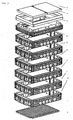
- FIG. 1 shows in an exploded perspective view of the components of a shaft with modular manhole structure, which is useful for the inventive system.
- the shaft consists of a base plate 1, a plurality of interconnected frame members 2, a head frame 3, a resting on steel frame 4 and a cover 5, which is closed by a locking device, not shown, which is operable only with a special key or tool, so that the shaft can only be opened by a person authorized to do so.
- FIG. 2 shows the plastic shaft or junction box in an assembled state.
- the illustrated shaft contains five frame elements 2 and has a clear width of 800 mm x 1.165 mm.
- the shaft height is approx. 1,620 mm.
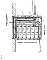
- FIG. 3 shows in a purely schematic representation of the system according to the invention.
- the shaft 6 which has a rectangular shape in plan, is in the Near a narrow side wall 7 a waterproof housing 8 is arranged, which has a bottom plate 9, an ETS frame 10 disposed thereon and an upper housing part 11 which covers the ETS frame 10 in the manner of an airtight bell and is lockable with the bottom plate 9, which is indicated by the reference numeral 12.
- the bottom plate 9 Through the bottom plate 9 extend divisible cable entries 13, which are waterproof sealed by sealing sets, not shown.
- the distribution devices such as Industries terminations, fiber optic connection panels, etc., and optionally a power supply and a 230 V connection unit are attached.
- the cables 16 are inserted through the bottom frame member in the shaft 6, by breaking predetermined breaking areas in the housing 8 opposite narrow side wall. The remaining openings are closed by sealing plugs.
- the cables 16 extend below the bottom 15 through the cable space 14 and are guided along curved ramps 17 to the bottom plate 9 of the watertight housing 8, with suitable seals 18 provide a watertight closure of the bottom plate 9.
- the upper housing part 11, which consists of the side walls 19 and the upper ceiling wall 20 and thereby forms an airtight bell or hood is releasably locked to the bottom plate 9.
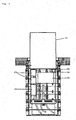
- FIG. 5 shows a longitudinal section through the shaft in the width direction with a view of the housing 8, the housing upper part 11 is pulled up so that assembly or service work can be performed on the manifold.
- the lower area of the installation space remains free of built-in components up to the height at which water can enter in the case described above.
- the housing top can be locked in the raised position by suitable means.
- FIG. 6 schematically shows in a size comparison a worker who kneels in the working position on the walkable, preferably Huaweistelzten bottom 15.
- the size comparison shows that there is enough space in the slot in front of the open case to perform the required work.
Landscapes
- Physics & Mathematics (AREA)
- General Physics & Mathematics (AREA)
- Optics & Photonics (AREA)
- Casings For Electric Apparatus (AREA)
- Installation Of Indoor Wiring (AREA)
Claims (3)
- Système de logement d'équipements de distribution ou d'objets similaires pour des câbles en cuivre et/ou en fibre de verre, doté d'un puits (6) qui comporte un couvercle (5) pouvant être verrouillé et peut être encastré au niveau du sol, et d'un boîtier (8) étanche à l'eau installé dans le puits (6), dans lequel sont logés les équipements de distribution ou les objets similaires, le boîtier (8) comportant une plaque de fond étanche à l'eau (9), au moins un bâti (10), fixé sur la plaque de fond, sur lequel sont installés les équipements de distribution ou les objets similaires, et une partie supérieure (11) du boîtier, qui est étanche à l'air, est formée d'un seul bloc, est composée de parois latérales (19) et d'une paroi couvrante supérieure (20), recouvre le ou les bâtis (10) et peut être reliée à la plaque de fond (9) de manière étanche à l'eau,
un espace de travail destiné à des travaux sur les équipements de distribution ou les objets similaires se trouvant dans le puits (6) devant le boîtier (8), et la partie supérieure (11) du boîtier pouvant être extraite par le haut après le déverrouillage de sorte que les équipements de distribution ou les objets similaires soient accessibles pour des travaux de montage et d'entretien,
caractérisé en ce que l'espace de travail est assez grand pour recevoir une personne travaillant et en ce que la partie supérieure du boîtier peut être arrêtée dans la position soulevée contre la paroi du puits. - Système selon la revendication 1,
caractérisé en ce que le puits (6) comporte dans sa partie inférieure un espace de réception de câbles (14) par lequel les câbles (16), introduits dans le puits (6) par des ouvertures latérales d'une paroi du puits, sont menés à la plaque de fond (9) du boîtier étanche à l'eau (8), et en ce que l'espace de réception de câbles (14) est limité par le haut par un plancher praticable (15). - Système selon la revendication 2,
caractérisé en ce que des rampes (17) incurvées depuis le sol de l'espace de réception de câbles (14) mènent à la plaque de fond (9) du boîtier (8).
Priority Applications (1)
| Application Number | Priority Date | Filing Date | Title |
|---|---|---|---|
| EP04009054A EP1587199B1 (fr) | 2004-04-16 | 2004-04-16 | Système de logement d'équipements de distribution de câbles à cuivre ou à fibres optiques |
Applications Claiming Priority (1)
| Application Number | Priority Date | Filing Date | Title |
|---|---|---|---|
| EP04009054A EP1587199B1 (fr) | 2004-04-16 | 2004-04-16 | Système de logement d'équipements de distribution de câbles à cuivre ou à fibres optiques |
Publications (2)
| Publication Number | Publication Date |
|---|---|
| EP1587199A1 EP1587199A1 (fr) | 2005-10-19 |
| EP1587199B1 true EP1587199B1 (fr) | 2011-12-21 |
Family
ID=34924623
Family Applications (1)
| Application Number | Title | Priority Date | Filing Date |
|---|---|---|---|
| EP04009054A Expired - Lifetime EP1587199B1 (fr) | 2004-04-16 | 2004-04-16 | Système de logement d'équipements de distribution de câbles à cuivre ou à fibres optiques |
Country Status (1)
| Country | Link |
|---|---|
| EP (1) | EP1587199B1 (fr) |
Families Citing this family (4)
| Publication number | Priority date | Publication date | Assignee | Title |
|---|---|---|---|---|
| DE102004033976B4 (de) | 2004-07-14 | 2010-09-23 | Berthold Sichert Gmbh | Dachmodul-Bausatz |
| FR3017022B1 (fr) * | 2014-01-24 | 2018-01-05 | Syndicat Intercommunal Pour Le Gaz Et L'electricite En Ile-De-France | Chambre pour un reseau de communications electroniques |
| DE102022114132A1 (de) * | 2022-06-03 | 2023-12-14 | Langmatz Gmbh | Schacht |
| DE102022114116A1 (de) * | 2022-06-03 | 2023-12-14 | Langmatz Gmbh | Schacht |
Citations (2)
| Publication number | Priority date | Publication date | Assignee | Title |
|---|---|---|---|---|
| DE3322584A1 (de) * | 1983-06-23 | 1983-11-24 | Krone Gmbh, 1000 Berlin | Gehaeuse in unterflurausfuehrung, insbesondere fuer fernmeldetechnische geraete |
| US5210374A (en) * | 1990-05-21 | 1993-05-11 | Channell William H | Terminal housing for buried communication lines |
Family Cites Families (5)
| Publication number | Priority date | Publication date | Assignee | Title |
|---|---|---|---|---|
| DE1952453U (de) | 1966-10-26 | 1966-12-29 | Krone Kg | Ueberflutsicherer behaelter zur aufnahme elektrischer bauteile. |
| US3482030A (en) * | 1968-09-30 | 1969-12-02 | Pepco Products Corp | Underground electrical conductor housing with inner bell-jar housing |
| NL1007973C2 (nl) * | 1998-01-07 | 1999-07-08 | Odink & Koenderink Bv | Voor verzonken plaatsing op (semi) openbaar terrein bestemde voedingkast voor particuliere en/of bedrijfsmatige spanningafname. |
| FR2784812B1 (fr) * | 1998-10-14 | 2001-02-02 | Alstom Technology | Dispositif de protection a l'immersion pour armoire, notamment electrique, escamotable dans le sol et module d'equipement dote d'un tel dispositif |
| NL1017089C2 (nl) * | 2001-01-12 | 2002-07-15 | Eijndhoven Internat B V Van | Ondergronds plaatsbare kabelverbindingskast. |
-
2004
- 2004-04-16 EP EP04009054A patent/EP1587199B1/fr not_active Expired - Lifetime
Patent Citations (2)
| Publication number | Priority date | Publication date | Assignee | Title |
|---|---|---|---|---|
| DE3322584A1 (de) * | 1983-06-23 | 1983-11-24 | Krone Gmbh, 1000 Berlin | Gehaeuse in unterflurausfuehrung, insbesondere fuer fernmeldetechnische geraete |
| US5210374A (en) * | 1990-05-21 | 1993-05-11 | Channell William H | Terminal housing for buried communication lines |
Also Published As
| Publication number | Publication date |
|---|---|
| EP1587199A1 (fr) | 2005-10-19 |
Similar Documents
| Publication | Publication Date | Title |
|---|---|---|
| DE10314897B3 (de) | System zur Unterbringung von Verteilereinrichtungen von Kupfer- und/oder Glasfaserkabeln | |
| DE19654594A1 (de) | Freiluftgehäuse zur Aufnahme von Telekommunikationseinrichtungen und Verfharen zur Unterstützung von Freiluftgehäusen | |
| WO2010089029A1 (fr) | Boîtier de terminaison de réseau en deux parties pour une terminaison de réseau optique | |
| DE3423184C2 (de) | Unterflurstation für Kabelverzweigereinrichtungen der Fernmeldetechnik | |
| DE3322584C2 (de) | Gehäuse in Unterflurausführung, insbesondere für fernmeldetechnische Geräte | |
| DE2740963A1 (de) | Anschlussvorrichtung in modulbauweise | |
| EP0929136B1 (fr) | Poste de distribution d'énergie placée à un endroit (semi)publique pour alimenter un particulier ou une entreprise | |
| EP1587199B1 (fr) | Système de logement d'équipements de distribution de câbles à cuivre ou à fibres optiques | |
| DE1949694C3 (de) | Unterirdisch angeordneter Niederspannungsverteiler | |
| EP0487802A1 (fr) | Répartiteur de télécommunication | |
| DE29818507U1 (de) | Verteilerschrank | |
| EP1555727B1 (fr) | Module de connexion | |
| DE19814647B4 (de) | Elektrischer Installationsgeräteträger | |
| DE102023113175B4 (de) | Verteilervorrichtung mit einer Funktionseinheit | |
| EP2749921B1 (fr) | Dispositif de répartition pour guide à fibres optiques | |
| EP0626599B1 (fr) | Coffre de distribution | |
| DE102006056962B4 (de) | Anordnung aus einem Gehäuse mit Telekommunikationseinbauten und einer Energieanschlusssäule | |
| EP0599442B1 (fr) | Central téléphonique privé | |
| DE102018129234B4 (de) | Kollokationsmodul, Modulbaugruppe sowie Glasfaserverteilereinrichtung | |
| EP2757400B1 (fr) | Terminaison de fibres optiques en verre | |
| US9419425B2 (en) | Retractable termination pedestal | |
| DE3342566A1 (de) | Unterflur-gehaeuse, insbesondere fuer fernmeldetechnische geraete | |
| DE8418720U1 (de) | Sockel für Kabelverzweigergehäuse | |
| DE29606869U1 (de) | Brüstungskanal für elektrotechnische Installationen | |
| DE8707576U1 (de) | Aufnahmevorrichtung für Lichtwellenleiter-Verbindungen |
Legal Events
| Date | Code | Title | Description |
|---|---|---|---|
| PUAI | Public reference made under article 153(3) epc to a published international application that has entered the european phase |
Free format text: ORIGINAL CODE: 0009012 |
|
| 17P | Request for examination filed |
Effective date: 20050323 |
|
| AK | Designated contracting states |
Kind code of ref document: A1 Designated state(s): AT BE BG CH CY CZ DE DK EE ES FI FR GB GR HU IE IT LI LU MC NL PL PT RO SE SI SK TR |
|
| AX | Request for extension of the european patent |
Extension state: AL HR LT LV MK |
|
| AKX | Designation fees paid |
Designated state(s): CZ HU SK |
|
| REG | Reference to a national code |
Ref country code: DE Ref legal event code: 8566 |
|
| 17Q | First examination report despatched |
Effective date: 20090323 |
|
| GRAP | Despatch of communication of intention to grant a patent |
Free format text: ORIGINAL CODE: EPIDOSNIGR1 |
|
| RAP1 | Party data changed (applicant data changed or rights of an application transferred) |
Owner name: LANGMATZ GMBH |
|
| GRAS | Grant fee paid |
Free format text: ORIGINAL CODE: EPIDOSNIGR3 |
|
| GRAA | (expected) grant |
Free format text: ORIGINAL CODE: 0009210 |
|
| AK | Designated contracting states |
Kind code of ref document: B1 Designated state(s): CZ HU SK |
|
| REG | Reference to a national code |
Ref country code: SK Ref legal event code: T3 Ref document number: E 11240 Country of ref document: SK |
|
| PLBE | No opposition filed within time limit |
Free format text: ORIGINAL CODE: 0009261 |
|
| STAA | Information on the status of an ep patent application or granted ep patent |
Free format text: STATUS: NO OPPOSITION FILED WITHIN TIME LIMIT |
|
| 26N | No opposition filed |
Effective date: 20120924 |
|
| REG | Reference to a national code |
Ref country code: SK Ref legal event code: MM4A Ref document number: E 11240 Country of ref document: SK Effective date: 20120416 |
|
| PG25 | Lapsed in a contracting state [announced via postgrant information from national office to epo] |
Ref country code: SK Free format text: LAPSE BECAUSE OF NON-PAYMENT OF DUE FEES Effective date: 20120416 |
|
| REG | Reference to a national code |
Ref country code: HU Ref legal event code: AG4A Ref document number: E014632 Country of ref document: HU |
|
| PGFP | Annual fee paid to national office [announced via postgrant information from national office to epo] |
Ref country code: CZ Payment date: 20140409 Year of fee payment: 11 |
|
| PGFP | Annual fee paid to national office [announced via postgrant information from national office to epo] |
Ref country code: HU Payment date: 20140429 Year of fee payment: 11 |
|
| PG25 | Lapsed in a contracting state [announced via postgrant information from national office to epo] |
Ref country code: HU Free format text: LAPSE BECAUSE OF NON-PAYMENT OF DUE FEES Effective date: 20150417 Ref country code: CZ Free format text: LAPSE BECAUSE OF NON-PAYMENT OF DUE FEES Effective date: 20150416 |