EP0929136B1 - Power station placed on (semi)public ground to supply a private subscriber or a company - Google Patents
Power station placed on (semi)public ground to supply a private subscriber or a company Download PDFInfo
- Publication number
- EP0929136B1 EP0929136B1 EP98204440A EP98204440A EP0929136B1 EP 0929136 B1 EP0929136 B1 EP 0929136B1 EP 98204440 A EP98204440 A EP 98204440A EP 98204440 A EP98204440 A EP 98204440A EP 0929136 B1 EP0929136 B1 EP 0929136B1
- Authority
- EP
- European Patent Office
- Prior art keywords
- cover
- container
- power station
- pit box
- station according
- Prior art date
- Legal status (The legal status is an assumption and is not a legal conclusion. Google has not performed a legal analysis and makes no representation as to the accuracy of the status listed.)
- Expired - Lifetime
Links
Images

Classifications
-
- H—ELECTRICITY
- H02—GENERATION; CONVERSION OR DISTRIBUTION OF ELECTRIC POWER
- H02B—BOARDS, SUBSTATIONS OR SWITCHING ARRANGEMENTS FOR THE SUPPLY OR DISTRIBUTION OF ELECTRIC POWER
- H02B7/00—Enclosed substations, e.g. compact substations
- H02B7/06—Distribution substations, e.g. for urban network
- H02B7/08—Underground substations
-
- H—ELECTRICITY
- H02—GENERATION; CONVERSION OR DISTRIBUTION OF ELECTRIC POWER
- H02B—BOARDS, SUBSTATIONS OR SWITCHING ARRANGEMENTS FOR THE SUPPLY OR DISTRIBUTION OF ELECTRIC POWER
- H02B1/00—Frameworks, boards, panels, desks, casings; Details of substations or switching arrangements
- H02B1/26—Casings; Parts thereof or accessories therefor
- H02B1/50—Pedestal- or pad-mounted casings; Parts thereof or accessories therefor
- H02B1/505—Pedestal- or pad-mounted casings; Parts thereof or accessories therefor retractable installations
Definitions
- the invention relates to an energy distribution station, as defined in the first part of claim 1.
- Such an energy distribution station is in Document WO95 / 34113 (see in particular the implementation according to Fig. 6-8).
- the first cover forms the top wall of a station a corresponding recess in the second cover box movable upwards, in a vertical wall the sockets arranged sunk one above the other are.
- lids raised but also with closed lids can be between the top Edge of the pit housing and the peripheral edge of the second Lid and on the other hand between the edge of the recess in the second cover and the peripheral edge of the first cover (Rain) water flow into the pit housing, whereby the water through an opening in the bottom of the pit housing to be dissipated.
- a disadvantage of this known power distribution station is above all that the one containing the sockets Box in the extended use position susceptible to damage is and a cumbersome obstacle forms. Measures to ensure that the distribution station in sensitive areas, such as the sockets, too in the case of floods of the overshoot type or (extraordinary) high groundwater level kept water-free will not be shown.
- the invention has set itself the task of to create improved power distribution station which does not have the disadvantage mentioned and in particular also in Floods offer adequate protection.
- the container When the pit housing is full due to the base and / or rainwater, the container works like an air bell and the apparatus remains in the air bubble within the Bell out of contact with the water in the pit housing. It in this case it is proportional extensive and heavy bell, which only for periodic Maintenance of those to be protected by the air bell Equipment must be lifted out of the pit housing.
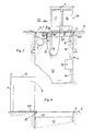
- the power distribution station has a recessed rectangular pit housing 1 from for example steel sheet treated against corrosion.
- the Pit housing 1 has a three along the top Sides extending channel profile 2, which on the fourth side (left in Fig. 1-3) on the space of the pit housing adjoined.
- the pit housing 1 is by means of two lids 3 and 4 lockable in the closed position with the road surface 5 (almost) lie on a common level.
- the cover 3 is designed to be hinged about an axis 3a, while the cover 4 in guide rails 6 between the closed position according to FIGS. 1 and 2 and the open 3 is movably guided.
- cross walls 7 formed a number of departments which can be closed overall by the cover 3. In these departments, those are for home use or operational use certain outlets 8 housed Service.
- the transverse walls 7 are at the top by means of a vertical connecting wall 9, which the departments from separates the remaining space 10 of the pit housing 1 with each other connected.
- the sockets 8 are separate or in groups normally - with lid 3 closed - open at the bottom and attached to the rest of closed containers 11.
- closed lid 3 (Fig. 1 and 3) are the containers 11 on the vertical wall 9 and the lid 3 is on the Top of the container 11 or. the top edges of the Partition walls 7.
- the containers 11 are independent of one another Axis 12 rotatably mounted, which is at a short distance from and provided parallel to the axis of rotation 3a of the cover 3 is.
- On the departments with containers 11 turned away pit wall is the so-called junction box 13 attached extendable upwards.
- This Junction box goes the stiff (5-wire) entering below Basic cable 14 in a flexible multi-core cable 15 over which to a box carried by the lid 4 16 leads in which under the management of the energy supplier vertical safety and measuring equipment housed is.
- the box 16 has a cable connection with the also carried by the cover 4 unit 17, which by means of a separate flexible cable 18 with the sockets 8 is connected. Within the unit 17, the over the different sockets 8 removed amounts of energy measured and registered.
- the boxes 16 and 17 are suspended from the lid 4 in a open at the bottom and closed at the rest Container 19 arranged, which container with the lid 4th can be moved up and down via the guide rail 6.
- the drawing shows the distribution station in the Situation in which the rainwater / groundwater within of the pit housing 1 to the level labeled 25 has risen.
- the socket 8 is in combination with a waterproof at the end of a consumer cable 24 attached connector 23 shown. 1 and 3 lies the connection point between socket and plug within the protective against the penetration of water Bubble.
- the lid 4 is normally in the closed position 1 and 2 by means of (not closer in the drawing locking means locked, which means 1 and 2 on the cover 4 can take up acting pressure.
- the container 19 is first, under which Influence of the above upward pressure, slightly from the room 10 of the pump housing move up while additional Lifting devices will be required around the container 19 to be able to lift completely (according to FIG. 3) out of the water.
- the one in the drawing with the rainwater / groundwater level 25 indicated state is a state in the generally will not occur for a long time.
- the level will be 25 (far) below the bottom of the container 19 lowered in the space 10 of the pit housing so that the container moves up and down slightly can be and tilted into the position shown in FIG. 4 can.
- Lids 3 and 4 and the support means designed for this difficult are around the load in the closed position to be able to record the traffic traveling over it. It plays an important role in lid support the channel profile designated 26.
Abstract
Description
Die Erfindung betrifft eine Energieverteilungsstation, wie definiert im ersten Teil des Anspruchs 1.The invention relates to an energy distribution station, as defined in the first part of claim 1.
Eine derartige Energieverteilungsstation ist im Dokument WO95/34113 (siehe insbesondere die Ausführung nach Fig. 6-8) offenbart worden. Bei dieser bekannten Station bildet der erste Deckel die obere Wand eines durch eine entsprechende Aussparung im zweiten Deckel hindurch nach oben bewegbaren Kastens, in einer senkrechten Wand desselben die Steckdosen übereinander versenkt angeordnet sind. Nicht nur bei angehobenen Deckeln, sondern auch bei geschlossenen Deckeln kann einerseits zwischen dem oberen Rand des Grubengehäuses und dem Umfangsrand des zweiten Deckels und andererseits zwischen dem Rand der Aussparung im zweiten Deckel und dem Umfangsrand des ersten Deckels (Regen)wasser in das Grubengehäuse hineinströmen, wobei das Wasser durch eine Öffnung im Boden des Grubengehäuses abgeführt werden soll.Such an energy distribution station is in Document WO95 / 34113 (see in particular the implementation according to Fig. 6-8). In this known The first cover forms the top wall of a station a corresponding recess in the second cover box movable upwards, in a vertical wall the sockets arranged sunk one above the other are. Not only with lids raised, but also with closed lids can be between the top Edge of the pit housing and the peripheral edge of the second Lid and on the other hand between the edge of the recess in the second cover and the peripheral edge of the first cover (Rain) water flow into the pit housing, whereby the water through an opening in the bottom of the pit housing to be dissipated.
Ein Nachteil dieser bekannten Energieverteilungsstation ist vor allem, dass der die Steckdosen enthaltende Kasten in der nach oben ausgefahrenen Gebrauchslage beschädigungsempfindlich ist und ein hinderliches Obstakel bildet. Massnahmen, dahin gehend, dass die Verteilungsstation an empfindlichen Stellen, wie die Steckdosen, auch bei Hochwasser vom Überschwingungstyp oder bei (ausserordentlich) hohem Grundwasserstand wasserfrei gehalten wird, werden nicht gezeigt.A disadvantage of this known power distribution station is above all that the one containing the sockets Box in the extended use position susceptible to damage is and a cumbersome obstacle forms. Measures to ensure that the distribution station in sensitive areas, such as the sockets, too in the case of floods of the overshoot type or (extraordinary) high groundwater level kept water-free will not be shown.
Die Erfindung hat sich zur Aufgabe gestellt, eine verbesserte Energieverteilungsstation zu schaffen, welche den genannten Nachteil nicht hat und insbesondere auch bei Hochwasser einen ausreichenden Schutz bietet.The invention has set itself the task of to create improved power distribution station which does not have the disadvantage mentioned and in particular also in Floods offer adequate protection.
Erfindungsgemäss wird diese Aufgabe gelöst durch die im zweiten Teil des Anspruchs 1 beschriebenen Merkmale.According to the invention, this object is achieved by Features described in the second part of claim 1.
Infolge der erfindungsgemässen Massnahmen darf der Spiegel des Grundwassers bezw. des Regenwassers im Grubengehäuse, während der jeweilige Deckel verschlossen ist, ohne Bedenken bis oberhalb der unteren Ränder der Steckdosenbehälter steigen. Die Steckdosen bleiben dabei ja ausser Berührung mit dem (steigenden) Wasser, indem die sie aufnehmenden Behälter wie eine Luftglocke arbeiten.As a result of the measures according to the invention, the Groundwater level or the rainwater in the pit housing, while the respective lid is closed, without hesitation up to the lower edges of the socket holder climb. The sockets remain so out of contact with the (rising) water by the they work as an air bell.
Zu bemerken ist, dass die amerikanische Patentschrift
2 247 936 (siehe insbesondere die Ausführungsform nach
Fig. 4 und 5) ein im Boden gesenktes, mit einem Deckel
verschliessbares Grubengehäuse offenbart ist, in dem ein
unten offener und zum übrigen geschlossener, zylindrischer
Behälter vorgesehen ist. Dieser Behälter stützt mit seinem
unteren Rand auf dem Boden des Grubengehäuses und enthält
elektrische Wiederholungsapparatur für ein Fernmeldesystem.It should be noted that the
Beim Vollaufen des Grubengehäuses durch Grund- und/ oder Regenwasser arbeitet der Behälter wie eine Luftglocke und bleibt die Apparatur in der Luftblase innerhalb der Glocke ausser Kontakt mit dem Wasser im Grubengehäuse. Es handelt sich in diesem Fall um eine verhältnismässig umfangreiche und schwere Glocke, welche nur zur periodischen Wartung der durch die Luftglocke zu schutzenden Apparatur aus dem Grubengehäuse gehoben werden muss.When the pit housing is full due to the base and / or rainwater, the container works like an air bell and the apparatus remains in the air bubble within the Bell out of contact with the water in the pit housing. It in this case it is proportional extensive and heavy bell, which only for periodic Maintenance of those to be protected by the air bell Equipment must be lifted out of the pit housing.
Weiterhin soll bemerkt werden, dass im nicht vorveröffentlichten Dokument EP-A-0905842 eine Energieverteilungsstation der obigen Gattung beschrieben wird, wobei eine Anzahl von nebeneinander angeordneten Steckdosen in einer Abteilung eines Grubengehäuses untergebracht sind, welche Abteilung mittels eines Klappdeckels verschliessbar ist und wobei in der Schliesslage dieses Deckels ebenfalls ein Spalt zwischen dem freien Längsrand des Deckels und dem benachbarten oberen Rand des Grubengehäuses vorhanden ist, durch den ein an einer Steckdose angeschlossenes Verbraucherkabel nach aussen passieren kann. In der Ausführung nach dem Dokument EP-A-0905842 sind die Steckdosen jedoch in einer festen Position innerhalb des Grubengehäuses angeordnet und fehlen Massnahmen, wodurch bei Hochwasser vom Überschwimmungstyp oder bei (ausserordentlich) hohem Grundwasserstand die Verteilungsstation an empfindlichen Stellen, wie die Steckdosen, wasserfrei gehalten werden können.It should also be noted that in the unpublished Document EP-A-0905842 an energy distribution station of the above genus is described, wherein a number of sockets arranged side by side in a department of a pit housing, which department can be closed with a hinged lid is and also in the closed position of this lid a gap between the free longitudinal edge of the lid and the adjacent upper edge of the pit housing through which is connected to an electrical outlet Consumer cable can pass outside. In execution according to document EP-A-0905842 are the sockets however in a fixed position within the pit housing ordered and lack of measures, resulting in flood of the overflow type or at (extraordinary) high groundwater level the distribution station at sensitive Places, like the sockets, kept water-free can be.
Praktische weitere Ausbildungen der Erfindung sind in den Unteransprüchen definiert worden.Practical further developments of the invention are in the sub-claims have been defined.
Die Erfindung wird unten an Hand der Zeichnung mit einem Ausführungsbeispiel näher erläutert.The invention is shown below with reference to the drawing an embodiment explained in more detail.
Es zeigen:
Die erfindungsgemässe Energieverteilungsstation hat
ein im Boden versenktes rechteckiges Grubengehäuse 1 aus
zum Beispiel gegen Korrosion behandeltem Stahlblech. Das
Grubengehäuse 1 hat am oberen Rand ein sich längs drei
Seiten erstreckendes Rinnenprofil 2, das sich an der
vierten Seite (links in Fig. 1-3) am Raum des Grubengehäuses
anschliesst. The power distribution station according to the invention has
a recessed rectangular pit housing 1 from
for example steel sheet treated against corrosion. The
Pit housing 1 has a three along the top
Sides extending
Das Grubengehäuse 1 ist mittels zwei Deckel 3 und 4
verschliessbar, die in der Schliesslage mit der Strassendecke
5 (nahezu) in einer gemeinsamen Ebene liegen.The pit housing 1 is by means of two
Der Deckel 3 ist um eine Achse 3a aufklappbar ausgebildet,
während der Deckel 4 in Führungsschienen 6 zwischen
der Schliesslage nach Fig. 1 und 2 und der geöffneten
Lage nach Fig. 3 bewegbar geführt ist.The
Im Raum des Grubengehäuses ist links in Fig. 3 mit
Hilfe von Querwänden 7 eine Anzahl von Abteilungen gebildet,
die insgesamt durch den Deckel 3 verschliessbar sind.
In diesen Abteilungen sind die für Privatgebrauch oder
betriebsmässige Verwendung bestimmten Steckdosen 8 untergebracht
worden. Die Querwände 7 sind oben mittels einer
senkrechten Verbindungswand 9, welche die Abteilungen vom
übrigen Raum 10 des Grubengehäuses 1 trennt, miteinander
verbunden.In the space of the pit housing is on the left in Fig. 3 with
Using
Die Steckdosen 8 sind gesondert oder gruppenweise in
normalerweise - bei geschlossenem Deckel 3 - unten offenen
und zum übrigen geschlossenen Behältern 11 angebracht. Bei
geschlossenem Deckel 3 (Fig. 1 und 3) liegen die Behälter
11 an der Vertikalwand 9 an und liegt der Deckel 3 auf der
Obenseite der Behälter 11 bezw. den oberen Rändern der
Trennungswände 7 an.The sockets 8 are separate or in groups
normally - with
Die Behälter 11 sind unabhängig voneinander um eine
Achse 12 drehbar montiert, welche in kurzem Abstand von
und parallel zu der Drehachse 3a des Deckels 3 vorgesehen
ist. Auf der von den Abteilungen mit den Behältern 11
abgekehrten Grubengehäusewand ist der sogenannte Übergangskasten
13 nach oben ausfahrbar befestigt. In diesem
Übergangskasten geht das unten hineintretende steife (5-adrige)
Grundkabel 14 in ein biegsames mehradriges Kabel
15 über, welches zu einem vom Deckel 4 getragenen Kasten
16 führt, in welchem die unter Verwaltung vom Energielieferanten
stehende Sicherungs- und Messapparatur untergebracht
ist. Der Kasten 16 hat eine Kabelverbindung mit der
ebenfalls vom Deckel 4 getragenen Einheit 17, welche
mittels gesonderter biegsamer Kabel 18 mit den Steckdosen
8 verbunden ist. Innerhalb der Einheit 17 werden die über
die unterschiedlichen Steckdosen 8 abgenommenen Energiemengen
gemessen und registriert.The
Die Kästen 16 und 17 sind in einem am Deckel 4 aufgehängten,
unten offenen und zum übrigen geschlossenen
Behälter 19 angeordnet, welcher Behälter mit dem Deckel 4
über die Führungsschiene 6 auf und ab bewegbar ist.The
Unten an der hinteren Wand des Behälters 19 (siehe
Fig. 3) sind zwei Koppelstücke 20 vorgesehen, die in der
oberen Lage des Behälters 19 (Fig. 3) auf einer an der
betreffenden Seite längs des oberen Randes des Grubengehäuses
gelagerten Drehungswelle 21 angreifen, in der
Weise, dass nach dem Zustandekommen des Eingriffs zwischen
den Koppelstücken 20 und der Drehungswelle 21 der Behälter
19 um die Drehachse 21 in die Lage gemäss Fig. 4 gekippt
werden kann, in welcher Lage die Kästen 16 und 17 für
Inspektion und andersartige Arbeiten zugänglich sind und
gegebenenfalls wie eine Schublade aus dem Behälter 19
gezogen werden können. In Fig. 4 sind die Kästen 16 und 17
nicht näher dargestellt.Below on the rear wall of the container 19 (see
Fig. 3) two
Die Zeichnung zeigt die Verteilungsstation in der
Situation, in der das Regenwasser/Grundwasser innerhalb
des Grubengehäuses 1 bis auf das mit 25 bezeichnete Niveau
gestiegen ist. Dies bedeutet, dass in Fig. 1, wo die
beiden Deckel 3 und 4 in einer nicht näher dargestellten
Weise in der geschlossenen Lage verriegelt sind, sowohl
innerhalb der Behälter 11, wie auch innerhalb des Behälters
19 eine Luftblase vorhanden ist, innerhalb welcher
die Steckdosen 8 bezw. die Kästen 17 und 16 gegen Hineindringen
von Wasser geschützt sind.The drawing shows the distribution station in the
Situation in which the rainwater / groundwater within
of the pit housing 1 to the level labeled 25
has risen. This means that in Fig. 1, where the
two
Nach Entriegeln und Aufklappen des Deckels 3 kann ein
ausgewählter Behälter 11 aus der Lage nach Fig. 1 in diejenige
nach Fig. 2 gebracht werden, zu welchem Zweck der
Behälter mit einem nicht näher gezeigten Griff versehen
sein kann.After unlocking and opening the
In der Zeichnung ist die Steckdose 8 in Kombination
mit einem wasserdicht am Ende eines Verbraucherkabels 24
angebrachten Stecker 23 gezeigt. In Fig. 1 und 3 liegt
die Verbindungsstelle zwischen Steckdose und Stecker
innerhalb der gegen das Hineindringen von Wasser schützenden
Luftblase.In the drawing, the socket 8 is in combination
with a waterproof at the end of a
Normalerweise wird der Deckel 4 in der Schliesslage
nach Fig. 1 und 2 mittels (in der Zeichnung nicht näher
gezeigter) Verriegelungsmittel verriegelt, welche Mittel
den in der Situation nach Fig. 1 und 2 auf dem Deckel 4
wirkenden Aufwärtsdruck aufnehmen können. Bei Entriegelung
des Deckels 4 wird der Behälter 19 zunächst, unter dem
Einfluss des genannten Aufwärtsdrucks, leicht aus dem Raum
10 des Pumpengehäuses nach oben bewegen, während zusätzliche
Hebemittel benötigt sein werden um den Behälter 19
ganz (gemäss Fig. 3) aus dem Wasser heben zu können.The
Der in der Zeichnung mit dem Regenwasser/Grundwasserniveau
25 angedeutete Zustand ist ein Zustand, der im
allgemeinen nicht für längere Zeit auftreten wird. Normalerweise
wird das Niveau 25 (weit) unten dem unteren Rand
des im Raum 10 des Grubengehäuses gesenkten Behälters 19
liegen, sodass der Behälter dann leicht auf und ab bewegt
werden kann und in die Lage nach Fig. 4 gekippt werden
kann.The one in the drawing with the rainwater /
Schliesslich soll noch bemerkt werden, dass die Deckel 3 und 4 und die Stützmittel dafür schwer ausgebildet sind um in der geschlossenen Position die Belastung des darüber fahrenden Verkehrs aufnehmen zu können. Eine wichtige Rolle im Deckelunterstützung erfüllt dabei das mit 26 bezeichnete Rinnenprofil.Finally, it should be noted that the Lids 3 and 4 and the support means designed for this difficult are around the load in the closed position to be able to record the traffic traveling over it. It plays an important role in lid support the channel profile designated 26.
Claims (6)
- A power station adapted to be sunk in place on (semi)public ground to supply a private subcriber or a company, comprising a pit box (1) to be sunk into the ground, said pit box having a first compartment with power plug sockets (8) contained therein and closable by a first cover (3), and a compartment which is closable by a second cover (4) for receiving a transition cabinet (13) to be connected to an underground cable (14), wherein said second cover (4) carries at least one additional cabinet (16, 17) to be connected - through flexible cables (15; 18) - to said transition cabinet (13) and the power plug sockets (8) respectively and adapted to contain safety and measuring equipment, and wherein the power plug sockets on one hand and the cabinet(s) containing safety and measuring equipment on the other hand are mounted for movement from the respective compartments by lifting said first (3) and said second cover (4) respectively, characterized in that the power plug sockets (8) are mounted - either individually or in groups and arranged side by side - in containers (11) which are open at the bottom and for the rest completely closed, said container(s) being connected to said first cover (3) which is formed as a hinged lid, wherein in the closed position of the latter there is a slit between the free longitudinal edge of the first cover (3) and the adjacent upper edge of the pit box, through which a supply cable connected to a power plug socket may pass from the pit box to the outside of the latter.
- A power station according to claim 1, characterized in that the container (11) ccontaining said power plug sockets (8) are mounted to be tilted upwardly about an axis (12) which is parallel to the hinge axis (3a) of the respective cover (3).
- A power station according to claims 1-2, characterized in that fixed partitions (7) are provided which separate said containers (11) from one another, when the latter are in their lowered positions within the pit box (1).
- A power station according to claims 1-3, characterized in that said cabinets (16, 17) containing safety and measuring equipment are also mounted in a container (19) which is open at the bottom and for the rest completely closed, said container (19) being mounted for an up and down movement in the space (10) of the pit box (1), such that it may be lifted together with said second cover (4) to a position above said pit box (1).
- A power station according to claim 4, characterized in that the up and down movable container (19) for the cabinets (16, 17) containing said safety and measuring equipment is carrying on one side - at the bottom - coupling members (20) adapted to engage a shaft mounted along the upper edge of the pit box (1) when the container (19) is in its lifted position, in such a way that the container (19) may be tilted about said shaft (21) from the lifted position into a position laterally outside of said pit box (1).
- A power station according to claim 5, characterized in that the cabinets (16, 17) containing said safety and measuring equipment are mounted to be pulled out from the tilted container (19) like a drawer.
Applications Claiming Priority (2)
| Application Number | Priority Date | Filing Date | Title |
|---|---|---|---|
| NL1007973 | 1998-01-07 | ||
| NL1007973A NL1007973C2 (en) | 1998-01-07 | 1998-01-07 | Power supply box for recessed installation in (semi) public areas for private and / or commercial voltage drop. |
Publications (2)
| Publication Number | Publication Date |
|---|---|
| EP0929136A1 EP0929136A1 (en) | 1999-07-14 |
| EP0929136B1 true EP0929136B1 (en) | 2002-04-10 |
Family
ID=19766306
Family Applications (1)
| Application Number | Title | Priority Date | Filing Date |
|---|---|---|---|
| EP98204440A Expired - Lifetime EP0929136B1 (en) | 1998-01-07 | 1998-12-23 | Power station placed on (semi)public ground to supply a private subscriber or a company |
Country Status (6)
| Country | Link |
|---|---|
| EP (1) | EP0929136B1 (en) |
| AT (1) | ATE216142T1 (en) |
| DE (1) | DE59803718D1 (en) |
| DK (1) | DK0929136T3 (en) |
| ES (1) | ES2175605T3 (en) |
| NL (1) | NL1007973C2 (en) |
Cited By (1)
| Publication number | Priority date | Publication date | Assignee | Title |
|---|---|---|---|---|
| DE102009057437A1 (en) * | 2009-12-09 | 2011-06-16 | Sew-Eurodrive Gmbh & Co. Kg | Arrangement for inductive charging of an energy storage vehicle and charging station |
Families Citing this family (12)
| Publication number | Priority date | Publication date | Assignee | Title |
|---|---|---|---|---|
| NL1021135C2 (en) * | 2002-07-23 | 2004-01-27 | Odink & Koenderink Bv | Protective cabinet for electronic and / or electrical equipment with water and gas-tight cable entry. |
| DE10314897B3 (en) * | 2003-04-01 | 2004-10-14 | Lic Langmatz Gmbh | Housing system for copper and/or glass fibre cable distributors has water-tight housing received in shaft embedded in ground |
| NL1025439C2 (en) * | 2004-02-06 | 2005-08-09 | Seijsener Recreatietechniek B | Installation is for creating facilities, such as electricity and water, for vessel berthed near to a landing stage |
| EP1587199B1 (en) * | 2004-04-16 | 2011-12-21 | Langmatz GmbH | System for housing copper or fiber optic cable distribution equipments |
| DE202010009603U1 (en) * | 2010-06-28 | 2010-11-11 | Kubik, Ralf | Water-protected raising and lowering of distributions in underfloor systems |
| DE102014017720B4 (en) * | 2014-12-02 | 2019-12-05 | Langmatz Gmbh | Underfloor arrangement of electrical and / or electronic devices, in particular telecommunications |
| NL2015564B1 (en) * | 2015-10-05 | 2017-05-17 | Brainwave B V | Underground power supply system, in particular an underground vehicle charging station and a method to charge an electric vehicle. |
| DE102016112613B4 (en) * | 2016-07-08 | 2019-06-27 | EnBW Energie Baden-Württemberg AG | Charging station for electric vehicles and charging port for a charging station |
| CN108819998A (en) * | 2018-07-31 | 2018-11-16 | 国网河南省电力公司唐河县供电公司 | A kind of trolley type maintenance power supply device |
| CN111555161B (en) * | 2019-11-11 | 2021-11-12 | 芜湖金牛电气股份有限公司 | Work control method of power distribution cabinet convenient to maintain |
| CZ309672B6 (en) * | 2022-05-24 | 2023-07-05 | AŽD Praha s.r.o | Barrier well |
| WO2024002505A1 (en) * | 2022-06-29 | 2024-01-04 | Pierburg Gmbh | Curb or paving stone charging device for charging an energy store of an electrically driven vehicle |
Family Cites Families (2)
| Publication number | Priority date | Publication date | Assignee | Title |
|---|---|---|---|---|
| FR2721147B1 (en) * | 1994-06-08 | 1996-07-19 | Philippe Lecreux | Technical service unit. |
| DE29620779U1 (en) * | 1996-11-29 | 1997-02-06 | Moser Herbert | Lowering arrangement |
-
1998
- 1998-01-07 NL NL1007973A patent/NL1007973C2/en not_active IP Right Cessation
- 1998-12-23 DE DE59803718T patent/DE59803718D1/en not_active Expired - Fee Related
- 1998-12-23 ES ES98204440T patent/ES2175605T3/en not_active Expired - Lifetime
- 1998-12-23 DK DK98204440T patent/DK0929136T3/en active
- 1998-12-23 AT AT98204440T patent/ATE216142T1/en not_active IP Right Cessation
- 1998-12-23 EP EP98204440A patent/EP0929136B1/en not_active Expired - Lifetime
Cited By (2)
| Publication number | Priority date | Publication date | Assignee | Title |
|---|---|---|---|---|
| DE102009057437A1 (en) * | 2009-12-09 | 2011-06-16 | Sew-Eurodrive Gmbh & Co. Kg | Arrangement for inductive charging of an energy storage vehicle and charging station |
| DE102009057437B4 (en) | 2009-12-09 | 2023-03-16 | Sew-Eurodrive Gmbh & Co Kg | Arrangement for inductive charging of an energy storage vehicle and charging station |
Also Published As
| Publication number | Publication date |
|---|---|
| DE59803718D1 (en) | 2002-05-16 |
| NL1007973C2 (en) | 1999-07-08 |
| ATE216142T1 (en) | 2002-04-15 |
| EP0929136A1 (en) | 1999-07-14 |
| ES2175605T3 (en) | 2002-11-16 |
| DK0929136T3 (en) | 2002-07-01 |
Similar Documents
| Publication | Publication Date | Title |
|---|---|---|
| EP0929136B1 (en) | Power station placed on (semi)public ground to supply a private subscriber or a company | |
| DE2953103C2 (en) | ||
| DE3423184C2 (en) | Underfloor station for cable distribution equipment in telecommunications | |
| DE2116402B2 (en) | Floor connection device for electrical underfloor installations | |
| DE202018100726U1 (en) | gutter system | |
| DE2116401C3 (en) | Floor connection device for electrical underfloor installations | |
| DE1949694C3 (en) | Low-voltage distributor arranged underground | |
| EP0905842B1 (en) | Power station placed on semi-public ground to supply a private subscriber or a company | |
| DE2643201B2 (en) | Loader chassis | |
| EP1587199B1 (en) | System for housing copper or fiber optic cable distribution equipments | |
| DE102018005962B4 (en) | Underfloor shaft, in particular for power distribution and/or telecommunications | |
| DE29908863U1 (en) | Access, revision and distribution shaft with house connection angle plate | |
| EP0982822A1 (en) | Distribution station for electricity | |
| DE3011619C2 (en) | Switchgear cabinet for transportable signal systems | |
| DE102013012079B4 (en) | Apparatus for the supply, in particular of ships, with electric energy and method for securing such a device | |
| WO2012052001A1 (en) | Media column | |
| DE3439620C1 (en) | Transportable tool for the underground driving of product pipes | |
| DE1665678C3 (en) | Floor connection device for electrical underfloor installations | |
| DE3740486C2 (en) | ||
| DE3907412A1 (en) | Housing system for accommodating electrical push-in units | |
| DE19507377A1 (en) | Heater box for tram rail shunting systems | |
| DE7223445U (en) | Switchgear | |
| DE7530099U (en) | Device for ceiling mounting of electrosurgical devices and peroperative monitoring devices | |
| EP0940898B1 (en) | Cable connection box in a distribution station apt to be lowered underground | |
| DE8008254U1 (en) | Switchgear cabinet for transportable signal systems |
Legal Events
| Date | Code | Title | Description |
|---|---|---|---|
| PUAI | Public reference made under article 153(3) epc to a published international application that has entered the european phase |
Free format text: ORIGINAL CODE: 0009012 |
|
| AK | Designated contracting states |
Kind code of ref document: A1 Designated state(s): AT BE CH DE DK ES FR GB IE IT LI LU MC NL |
|
| AX | Request for extension of the european patent |
Free format text: AL;LT;LV;MK;RO;SI |
|
| 17P | Request for examination filed |
Effective date: 19990630 |
|
| AKX | Designation fees paid |
Free format text: AT BE CH DE DK ES FR GB IE IT LI LU MC NL |
|
| GRAG | Despatch of communication of intention to grant |
Free format text: ORIGINAL CODE: EPIDOS AGRA |
|
| 17Q | First examination report despatched |
Effective date: 20010307 |
|
| GRAG | Despatch of communication of intention to grant |
Free format text: ORIGINAL CODE: EPIDOS AGRA |
|
| GRAG | Despatch of communication of intention to grant |
Free format text: ORIGINAL CODE: EPIDOS AGRA |
|
| GRAH | Despatch of communication of intention to grant a patent |
Free format text: ORIGINAL CODE: EPIDOS IGRA |
|
| GRAH | Despatch of communication of intention to grant a patent |
Free format text: ORIGINAL CODE: EPIDOS IGRA |
|
| REG | Reference to a national code |
Ref country code: GB Ref legal event code: IF02 |
|
| GRAA | (expected) grant |
Free format text: ORIGINAL CODE: 0009210 |
|
| AK | Designated contracting states |
Kind code of ref document: B1 Designated state(s): AT BE CH DE DK ES FR GB IE IT LI LU MC NL |
|
| REF | Corresponds to: |
Ref document number: 216142 Country of ref document: AT Date of ref document: 20020415 Kind code of ref document: T |
|
| REG | Reference to a national code |
Ref country code: CH Ref legal event code: EP |
|
| REG | Reference to a national code |
Ref country code: CH Ref legal event code: NV Representative=s name: FELBER & PARTNER AG PATENTANWAELTE Ref country code: IE Ref legal event code: FG4D Free format text: GERMAN |
|
| REF | Corresponds to: |
Ref document number: 59803718 Country of ref document: DE Date of ref document: 20020516 |
|
| REG | Reference to a national code |
Ref country code: DK Ref legal event code: T3 |
|
| GBT | Gb: translation of ep patent filed (gb section 77(6)(a)/1977) |
Effective date: 20020708 |
|
| ET | Fr: translation filed | ||
| REG | Reference to a national code |
Ref country code: ES Ref legal event code: FG2A Ref document number: 2175605 Country of ref document: ES Kind code of ref document: T3 |
|
| PLBE | No opposition filed within time limit |
Free format text: ORIGINAL CODE: 0009261 |
|
| STAA | Information on the status of an ep patent application or granted ep patent |
Free format text: STATUS: NO OPPOSITION FILED WITHIN TIME LIMIT |
|
| 26N | No opposition filed |
Effective date: 20030113 |
|
| PGFP | Annual fee paid to national office [announced via postgrant information from national office to epo] |
Ref country code: NL Payment date: 20041129 Year of fee payment: 7 |
|
| PGFP | Annual fee paid to national office [announced via postgrant information from national office to epo] |
Ref country code: MC Payment date: 20041201 Year of fee payment: 7 |
|
| PGFP | Annual fee paid to national office [announced via postgrant information from national office to epo] |
Ref country code: AT Payment date: 20041202 Year of fee payment: 7 |
|
| PGFP | Annual fee paid to national office [announced via postgrant information from national office to epo] |
Ref country code: IE Payment date: 20041222 Year of fee payment: 7 Ref country code: CH Payment date: 20041222 Year of fee payment: 7 |
|
| PGFP | Annual fee paid to national office [announced via postgrant information from national office to epo] |
Ref country code: LU Payment date: 20041227 Year of fee payment: 7 |
|
| PG25 | Lapsed in a contracting state [announced via postgrant information from national office to epo] |
Ref country code: IT Free format text: LAPSE BECAUSE OF NON-PAYMENT OF DUE FEES Effective date: 20051223 Ref country code: AT Free format text: LAPSE BECAUSE OF NON-PAYMENT OF DUE FEES Effective date: 20051223 |
|
| PG25 | Lapsed in a contracting state [announced via postgrant information from national office to epo] |
Ref country code: MC Free format text: LAPSE BECAUSE OF NON-PAYMENT OF DUE FEES Effective date: 20051231 Ref country code: LU Free format text: LAPSE BECAUSE OF NON-PAYMENT OF DUE FEES Effective date: 20051231 Ref country code: LI Free format text: LAPSE BECAUSE OF NON-PAYMENT OF DUE FEES Effective date: 20051231 Ref country code: CH Free format text: LAPSE BECAUSE OF NON-PAYMENT OF DUE FEES Effective date: 20051231 |
|
| PG25 | Lapsed in a contracting state [announced via postgrant information from national office to epo] |
Ref country code: NL Free format text: LAPSE BECAUSE OF NON-PAYMENT OF DUE FEES Effective date: 20060701 |
|
| REG | Reference to a national code |
Ref country code: CH Ref legal event code: PL |
|
| NLV4 | Nl: lapsed or anulled due to non-payment of the annual fee |
Effective date: 20060701 |
|
| REG | Reference to a national code |
Ref country code: IE Ref legal event code: MM4A |
|
| PGFP | Annual fee paid to national office [announced via postgrant information from national office to epo] |
Ref country code: DK Payment date: 20081230 Year of fee payment: 11 |
|
| PGFP | Annual fee paid to national office [announced via postgrant information from national office to epo] |
Ref country code: ES Payment date: 20081226 Year of fee payment: 11 |
|
| PGFP | Annual fee paid to national office [announced via postgrant information from national office to epo] |
Ref country code: DE Payment date: 20090202 Year of fee payment: 11 |
|
| PGFP | Annual fee paid to national office [announced via postgrant information from national office to epo] |
Ref country code: GB Payment date: 20081229 Year of fee payment: 11 |
|
| PGFP | Annual fee paid to national office [announced via postgrant information from national office to epo] |
Ref country code: BE Payment date: 20090202 Year of fee payment: 11 |
|
| PGFP | Annual fee paid to national office [announced via postgrant information from national office to epo] |
Ref country code: FR Payment date: 20081217 Year of fee payment: 11 |
|
| BERE | Be: lapsed |
Owner name: *ODINK & KOENDERINK B.V. Effective date: 20091231 |
|
| REG | Reference to a national code |
Ref country code: DK Ref legal event code: EBP |
|
| GBPC | Gb: european patent ceased through non-payment of renewal fee |
Effective date: 20091223 |
|
| REG | Reference to a national code |
Ref country code: FR Ref legal event code: ST Effective date: 20100831 |
|
| PG25 | Lapsed in a contracting state [announced via postgrant information from national office to epo] |
Ref country code: FR Free format text: LAPSE BECAUSE OF NON-PAYMENT OF DUE FEES Effective date: 20091231 Ref country code: BE Free format text: LAPSE BECAUSE OF NON-PAYMENT OF DUE FEES Effective date: 20091231 |
|
| PG25 | Lapsed in a contracting state [announced via postgrant information from national office to epo] |
Ref country code: DE Free format text: LAPSE BECAUSE OF NON-PAYMENT OF DUE FEES Effective date: 20100701 |
|
| PG25 | Lapsed in a contracting state [announced via postgrant information from national office to epo] |
Ref country code: GB Free format text: LAPSE BECAUSE OF NON-PAYMENT OF DUE FEES Effective date: 20091223 |
|
| PG25 | Lapsed in a contracting state [announced via postgrant information from national office to epo] |
Ref country code: DK Free format text: LAPSE BECAUSE OF NON-PAYMENT OF DUE FEES Effective date: 20100104 |
|
| REG | Reference to a national code |
Ref country code: ES Ref legal event code: FD2A Effective date: 20110309 |
|
| PG25 | Lapsed in a contracting state [announced via postgrant information from national office to epo] |
Ref country code: ES Free format text: LAPSE BECAUSE OF NON-PAYMENT OF DUE FEES Effective date: 20110308 |
|
| PG25 | Lapsed in a contracting state [announced via postgrant information from national office to epo] |
Ref country code: ES Free format text: LAPSE BECAUSE OF NON-PAYMENT OF DUE FEES Effective date: 20091224 |