EP0927883B1 - Verfahren zum untersuchen einer ungleichmässigkeit eines transparenten materials - Google Patents
Verfahren zum untersuchen einer ungleichmässigkeit eines transparenten materials Download PDFInfo
- Publication number
- EP0927883B1 EP0927883B1 EP98932551A EP98932551A EP0927883B1 EP 0927883 B1 EP0927883 B1 EP 0927883B1 EP 98932551 A EP98932551 A EP 98932551A EP 98932551 A EP98932551 A EP 98932551A EP 0927883 B1 EP0927883 B1 EP 0927883B1
- Authority
- EP
- European Patent Office
- Prior art keywords
- transparent material
- laser beam
- light
- inspecting
- ununiformity
- Prior art date
- Legal status (The legal status is an assumption and is not a legal conclusion. Google has not performed a legal analysis and makes no representation as to the accuracy of the status listed.)
- Expired - Lifetime
Links
Images


Classifications
-
- G—PHYSICS
- G01—MEASURING; TESTING
- G01N—INVESTIGATING OR ANALYSING MATERIALS BY DETERMINING THEIR CHEMICAL OR PHYSICAL PROPERTIES
- G01N21/00—Investigating or analysing materials by the use of optical means, i.e. using sub-millimetre waves, infrared, visible or ultraviolet light
- G01N21/84—Systems specially adapted for particular applications
- G01N21/88—Investigating the presence of flaws or contamination
- G01N21/95—Investigating the presence of flaws or contamination characterised by the material or shape of the object to be examined
- G01N21/958—Inspecting transparent materials or objects, e.g. windscreens
-
- G—PHYSICS
- G01—MEASURING; TESTING
- G01N—INVESTIGATING OR ANALYSING MATERIALS BY DETERMINING THEIR CHEMICAL OR PHYSICAL PROPERTIES
- G01N21/00—Investigating or analysing materials by the use of optical means, i.e. using sub-millimetre waves, infrared, visible or ultraviolet light
- G01N21/17—Systems in which incident light is modified in accordance with the properties of the material investigated
- G01N21/55—Specular reflectivity
- G01N21/552—Attenuated total reflection
-
- G—PHYSICS
- G01—MEASURING; TESTING
- G01N—INVESTIGATING OR ANALYSING MATERIALS BY DETERMINING THEIR CHEMICAL OR PHYSICAL PROPERTIES
- G01N21/00—Investigating or analysing materials by the use of optical means, i.e. using sub-millimetre waves, infrared, visible or ultraviolet light
- G01N21/84—Systems specially adapted for particular applications
- G01N21/88—Investigating the presence of flaws or contamination
- G01N21/89—Investigating the presence of flaws or contamination in moving material, e.g. running paper or textiles
- G01N21/892—Investigating the presence of flaws or contamination in moving material, e.g. running paper or textiles characterised by the flaw, defect or object feature examined
- G01N21/896—Optical defects in or on transparent materials, e.g. distortion, surface flaws in conveyed flat sheet or rod
- G01N2021/8965—Optical defects in or on transparent materials, e.g. distortion, surface flaws in conveyed flat sheet or rod using slant illumination, using internally reflected light
Definitions
- the present invention relates to a method of inspecting an optical ununiformity (defect) of a transparent material such as a glass substrate serving as a transparent substrate for a photo mask or a transparent substrate for an information recording medium and an apparatus therefore. More particularly, the invention relates to a method of inspecting an ununiformity of a transparent material, whereby the ununiformity of the transparent material can be detected at a high sensibility and a high speed by using characteristics of a total reflection on the surface of the transparent material.
- a photolithography method is used to form a fine pattern.
- a pattern is transferred onto a transparent substrate which was mirror-finished by polishing at a high precision by using a photo mask whose pattern was formed by a transparent film (for example, a chromium film).
- a method of inspecting the photo mask which can be said as an original board of the pattern as shown in a surface state inspecting apparatus disclosed in Japanese Patent Application Laid-Open No. 58-162038 (1983), a method of converging light onto a fine region on a pattern surface and comparing a reflection output and transmission output from the pattern surface has been known.
- a transparent substrate for an information recording medium from the viewpoints of the formation of an under layer and a magnetic layer having a good crystallinity which are formed on the surface of the transparent substrate, the low flotation of a magnetic head, and the like with the realization of high density recording, the transparent substrate having the surface polished at a high precision is required, so that the fine defect of the transparent substrate itself is also set to a target of the defect detection.
- existing defect inspecting method and apparatus do not necessarily satisfy a request of the defect detection.
- EP-A-497649 relates to a method and a device for testing the surface quality of a transmitting optical element, in particular a window of optronic visible and/or infrared observation equipment.
- This method consists in transmitting into the optical element a light flux which is labelled and confined inside this element, and in measuring the labelled light flux emerging from the element to be tested in the presence of surface defects.
- US-A-5355213 relates to an inspection system for detecting surface flaws in a transparent element which includes a source of electromagnetic radiation, such as a laser beam or visible light, with the radiation beam directed edgewise into the transparent element to be inspected at such an angle that the resulting internal angle is larger than the critical angle. This ensures that substantially all of the radiation will stay within the transparent element and exit through an opposing edge of the transparent element unless a surface flaw is encountered, in which case a portion of the radiation will exit the transparent element through the surface of the transparent element.
- a source of electromagnetic radiation such as a laser beam or visible light
- an object of the invention is to provide a method of inspecting an ununiformity of a transparent material, whereby a desired transparent material can be immediately extracted .
- a method of inspecting an ununiformity of a transparent material by introducing a laser beam into the transparent material wherein the transparent material has: at least one pair of total reflective surfaces in which the laser beam introduced in the transparent material repeats the total reflection and which face each other and at least one pair of turning surfaces which are arranged so as to face each other in the progressing direction of the laser beam that repeats the total reflection between the total reflective surfaces and progresses and which totally reflect the laser beam and return to the total reflective surfaces, when an optical path in the transparent material is optically uniformed, the laser beam is introduced in such a manner that the laser beam which propagates in the transparent material and impinges on the total reflective surfaces and the turning surfaces of the transparent material is propagated so as to totally reflect and repeat between at least the pair of turning surfaces and the laser beam is spread in an inspecting region which is formed by the propagation and is surrounded by the total reflective surfaces and the turning surfaces, and when an ununiform portion exists in the optical path of the laser beam which is introduced into the transparent material
- the laser beam introduced through the transparent material repeats the total reflection on the surface and is confined in the transparent material (the laser beam is spread), so that the light does not substantially leak to the outside (on the total reflective surfaces and turning surfaces).
- the total reflecting conditions are not satisfied and the light leaks out of the surface of the transparent material. That is, when the ununiform portion (defect) such as scratch, crack, and stain due to an adhering foreign matter exists on the surface of the transparent material, the light leaks out of the surfaces (total reflective surfaces and turning surfaces) as total reflective surfaces so long as the optical path is uniform.
- the inspecting method of the invention since the light is (substantially) confined in the transparent material by using the geometrical and optical total reflection serving as a physical critical phenomenon, responses to inspection light in the ununiform and uniform portions of the transparent material as an inspecting object are also critical, so that the ununiformity appears as a dramatic contrast. That is, the inspecting method of the invention can be called as an inspecting method for the defect (ununiformity) by a light confining method.
- a defect such as a very fine scratch of the transparent material is observed as light in a shielding case like a black box leaks out of a pinhole existing on the case.
- Incident conditions of the light for repeating the total reflection on the surface of the transparent material to (substantially) confine the light in the transparent material are obtained as follows.
- the conditions to (substantially) confine the light by the multiple total reflection in a rectangular transparent material like a transparent substrate will now be obtained hereinbelow.
- a refraction beam ⁇ Lt> when an incident beam ⁇ Li> impinges on a boundary surface between the refractive indices ni and nt is considered.
- a solvent vector which is perpendicular to the boundary surface and is directed to the side of an incident medium is set to ⁇ N> (unit vector).
- the vector ⁇ Lt> of the refraction beam exists on the flat surface extended by the vectors ⁇ N> and ⁇ Li> and can be expressed by a linear connection of ⁇ N> and ⁇ Li>. That is, it can be expressed as follows.
- ⁇ Lt> ⁇ Li> + ⁇ N>
- ⁇ and ⁇ are coefficients.
- an xy plane is considered as a first boundary surface of the total reflection.
- ⁇ Li> ⁇ Nz> cos( ⁇ - ⁇ 1)
- L1z -cos ⁇ 1 Since
- 1, the following equation is satisfied under conditions that ⁇ 1 ⁇ ⁇ c.
- L1x 2 + L1y 2 + cos 2 ⁇ 1 1
- the incident vector which can totally reflect on the xy plane of the first boundary surface exists on the outside of a circular cone in Fig. 28 obtained by rotating a straight line which forms a critical angle ⁇ c with the z axis around the z axis.
- the vectors which can satisfy the above-mentioned conditions infinitely exist.
- a vector ⁇ L3> after completion of the reflection is as follows.
- ⁇ L3> (+ ⁇ 1 - cos 2 ⁇ 1 - cos 2 2 ⁇ 1/2 ⁇ cos ⁇ 2, cos ⁇ 1)
- ⁇ L3> totally reflects on a third boundary surface
- the confinement of the light is succeeded.
- ⁇ L3> ⁇ Nx> cos( ⁇ - ⁇ 3)
- Nx (1, 0, 0).
- the total reflecting conditions with respect to the rectangular transparent material like a transparent substrate has been derived, it is also possible to decide the conditions of the incident angle of the light by a method similar to the above in a general form which will be described hereinlater.
- the conditions of the incident angle of the light which is introduced into the transparent material in the embodiment, which will be described hereinlater, are derived on the basis of the above.
- the transparent material can take any form of a square (rectangular) plate, a circular plate, an annular plate, a lens whose curved surface has a large curvature, a sphere, a polyhedron, a column, a cylinder, and a polyhedral column.
- the form of the transparent material is not limited.
- the transparent material has at least one pair of total reflective surfaces in which the light introduced through the transparent material repeats the total reflection and which face each other and at least one pair of turning surfaces which are arranged so as to face each other in the progressing direction of the laser beam that repeats the total reflection between the total reflective surfaces and propagates and which totally reflect and return the laser beam to the total reflective surfaces.
- the turning surfaces are important to confine the light in the transparent material. The turning surfaces have to be provided so as to face each other in the progressing direction of the light and it is necessary to provide at least one pair. The reason is that if the light does not repeat between the turning surfaces, the light cannot be confined.
- the introduction of the laser beam it is necessary to introduce the laser beam in such a manner that the laser beam introduced through the transparent material is propagated so that light which propagates in the transparent material and impinges on the total reflective surfaces and turning surfaces totally reflects and repeats between at least the pair of turning surfaces and the laser beam is spread in an inspecting region which is formed by the propagation and is surrounded by the total reflective surfaces and the turning surfaces.
- the laser beam is introduced in such a manner that the light introduced through the transparent material is propagated while repeating the total reflection between the total reflective surfaces which face each other, the light impinges on a turning surface (a) and totally reflects, after that, the light further repeats the propagation in the transparent material and totally reflects between at least one of turning surfaces (b), (c), ... except for the turning surface (a), and the light propagated in the turning surface (a) is again returned.
- the optical path in the transparent material is optically uniform. Even if there is no ununiform portion, the total reflection is repeated between the total reflective surfaces and turning surfaces.
- the confinement of the light is (substantially) realized.
- the light is confined on one certain plane of the transparent material.
- the confinement of the light is executed in almost the whole region of the transparent material.
- the ununiformity can be inspected by propagating the light so as to repeat the total reflection on at least two pairs of surfaces (at least one pair of total reflective surface and at least one pair of turning surfaces) which are provided on the outside of the transparent material and which face each other.
- the inspection can be executed in such a manner that a transparent vessel having mirror-finished surfaces is used, a transparent material is inserted into a medium (a liquid or the like) in the vessel, which has a refractive index larger than that of an external medium of the vessel, and the laser beam is introduced so as to repeat the total reflection on the external surface of the vessel and propagate.
- a transparent vessel having mirror-finished surfaces is used, a transparent material is inserted into a medium (a liquid or the like) in the vessel, which has a refractive index larger than that of an external medium of the vessel, and the laser beam is introduced so as to repeat the total reflection on the external surface of the vessel and propagate.
- the light satisfying the total reflecting conditions can be precisely introduced through the transparent material.
- the light satisfying the total reflecting conditions can be precisely introduced through the transparent material.
- an introducing surface to introduce the laser beam is provided in a portion sandwiched by one certain total reflective surface and at least one turning surface.
- the laser beam can be introduced from the total reflective surface or turning surface other than the introducing surface.
- an optical member made of a material having substantially the same refractive index as that of the transparent material has to be attached by an adhesive agent or the like, so that it takes much time. Since the optical member is attached to the total reflective surfaces or turning surfaces serving as inspecting regions, the light propagated in the transparent material does not satisfy the total reflecting conditions in the attached portion and the light leaks, so that the inspection cannot be substantially executed. Therefore, it is not preferable.
- the laser beam is introduced so as to emit the introduced laser beam into only the introducing surface and a surface in which an angle formed between the surface and introducing surface is almost equivalent to an angle formed between the surface and total reflective surface, thereby realizing the light confinement referred to in the present invention.
- the introducing surface of the transparent material to introduce the laser beam is mirror-polished.
- the laser beam is introduced so that the total reflection is repeated at the total reflective surfaces and turning surfaces and the light is confined.
- the introducing surface is mirror-polished, however, the introduced laser beam is not influenced due to a diffusion by the introducing surface and is propagated as parallel light as it is. Consequently, all of the light which impinges on the total reflective surfaces and turning surfaces is totally reflected, so that responses of the inspection light in the ununiform and uniform portions of the transparent material become more critical and the contrast is improved.
- it is desired that the whole surface (total reflective surfaces, turning surfaces, and introducing surfaces) of the transparent material is mirror-polished.
- the size of the total reflective surface is set to L
- the width of introducing surface is set to d
- the refractive index of the transparent material for the wavelength ⁇ of the laser beam is set to nt
- the refractive index of the external medium which is come into contact with the transparent material is set to ni
- a beam diameter of the laser beam is set to ⁇
- an angle of the light which first impinges on the total reflective surface or turning surface after the laser beam is introduced is set to ⁇ i.), and the number of reflecting times at the total reflective surfaces is set to m.
- m is expressed by a function of L, d, nt( ⁇ ), ni, ⁇ , and ⁇ 1
- conditions of at least one of L, d, nt( ⁇ ), ni, ⁇ , and ⁇ 1 are determined so that m is equal to a reference set value or more in a range where each ⁇ ik is equal to the critical angle ⁇ or more and the laser beam is introduced from the introducing surface of the transparent material.
- the beam locus is obtained by a simulation, the light introduced through the transparent material repeats the total reflection at the total reflective surfaces and turning surfaces and propagates, so that the width d of the introducing surface that the number of reflecting times until the light leaks out of the introducing surface increases is determined. Specifically speaking, it is sufficient that the width d of the introducing surface is reduced.
- the width d of the introducing surface is also limited by a beam diameter of the laser beam and a process for the transparent material, it is desirable that d is equal to 0.4 mm or less, preferably, 0,2 mm or less. When it is extremely reduced (it is smaller than 0.1 mm), since a break easily occurs on an interface between the total reflective surfaces and the introducing surface and an interface between the turning surfaces and the introducing surface, it is not preferable.
- nt the refractive index of the transparent material
- ⁇ of the laser beam the number of reflecting times on the total reflective surfaces
- the wavelength of the laser beam also exerts an influence onto a resolution of the ununiformity (scratch on the surface or the like). Since the maximum of the resolution of the ununiformity becomes the wavelength ⁇ of the laser beam, when it is desired to resolve and detect such a fine defect that the width of a scratch of a glass substrate for an electronic device is equal to 1 ⁇ m or less as an image, the wavelength of the laser beam is set to 1 ⁇ m or less.
- the transparent material has a certain specific form (for example, when the total reflective surfaces are perpendicular to the turning surfaces or the like), since the angle at which the beam impinges on each of the total reflective surfaces and turning surfaces has a predetermined relation with the angle ⁇ 1 at which the laser beam first impinges on the total reflective surfaces after completion of the introduction, m (the number of reflecting times on the total reflective surfaces) can be adjusted by properly adjusting the angle ⁇ 1.
- ⁇ 1 is adjusted so as to be equal to the reference design value m which permits the transparent material to be filled with light or more, and the laser beam is introduced.
- m which permits the transparent material to be filled with light or more
- the laser beam which is introduced through the transparent material can be detected at a high sensitivity and a high speed by fluctuating the incident angle within a range where the total reflection is caused and impinging the beam, so that the inspecting method having a high utility can be realized.
- the total reflective surfaces and turning surfaces of the transparent material have such a relation as to cross at right angles to each other.
- the introduced laser beam easily enters a state where it repeats the total reflection on the total reflective surfaces and turning surfaces and is confined in the transparent material.
- the inspection for the wide region of the transparent material can be simultaneously executed, so that a high speed inspection can be realized.
- the reason is that the incident angle of the light is the same on at least the pair of total reflective surfaces on which the introduced laser beam repeats the total reflection and, on at least the pair of turning surfaces as well, the incident angle of the light is the same, so that the light is propagated so as to have a predetermined relation (when the incident angle of the light on the total reflective surface is set to ⁇ , the incident angle of the light on the turning surface is equal to 90°- ⁇ ).
- the ununiformity in one certain plane in the inspecting region filled with the light due to such a fact that the light is propagated in the transparent material is inspected and, after that, the ununiformity of the inspecting region is inspected by relatively moving the plane of the inspection in the direction in which the inspecting region is filled with the light to the transparent material, so that the inspecting method can be simplified and it is preferable.
- a method of inspecting an ununiformity of a transparent material by introducing a laser beam through the transparent material, wherein the surface of the transparent material has at least one pair of main surfaces which are parallel to each other, at least one pair of end surfaces which intersect the main surfaces, and chamfer portions sandwiched by the main surfaces and end surfaces, when an optical path in the transparent material is optically uniform, a laser beam is introduced in such a manner that light which propagates in the transparent material and impinges on the main surfaces and the end surfaces of the transparent material is propagated so as to totally reflect and repeat between at least the pair of end surfaces and the laser beam is spread in an inspecting region which is formed by the propagation and is surrounded by the main surfaces, the end surfaces, and the chamfer portions, and when an ununiform portion exists in the optical path of the light introduced and propagated in the transparent material, the light that leaks out of the main surfaces and/or end
- the main surfaces, the end surfaces, and each of the chamfer portions correspond to the foregoing total reflective surfaces, the turning surfaces, and the introducing surface.
- a square (rectangular) plate, a circular plate, an annular plate, or the like can be mentioned.
- the introduced laser beam easily enters a state where the laser beam repeats the total reflection on the main surfaces and end surfaces and is (substantially) confined in the transparent material.
- the reason is as follows.
- each incident angle of the light on the main surfaces on which the introduced laser beam repeats the total reflection is the same and each incident angle of the light which impinges on the end surfaces is also the same. Since the light is propagated so that those incident angles keep a predetermined relation (when it is assumed that the incident angle of the light which impinges on the main surfaces is set to ⁇ , the incident angle of light which impinges on the end surfaces is equal to 90° - ⁇ ), the light confinement is (substantially) satisfied by merely setting so that the incident angle to the main surfaces on which the light first impinges after it introduces through the transparent material is larger than a critical point and the incident angle to the end surfaces is larger than the critical point.
- the laser beam is introduced so that a singular point that the laser beam geometrically and optically leaks out of the main surfaces and end surfaces does not substantially exist. Further, the laser beam is introduced so that the introduced laser beam is emitted from only the chamfer portions.
- the transparent material serving as an object of the ununiformity inspecting method is made of glass.
- the quality of material of the transparent material is decided in accordance with various uses. In case of glass, there are advantages that it is hard, a remarkably smooth surface can be obtained by mirror-polishing, light permeability is good, and the like.
- the ununiformity inspecting method exhibits the effect still more. Since a glass substrate having a surface polished at a high precision is required in association with the realization of high density of a pattern in recent years, the ununiformity inspecting method is effective in inspecting the ununiformity such as fine scratch or striae of the substrate which becomes an adverse influence on a formation or an exposure of the pattern.
- the ununiformity inspecting method exhibits the effect more and more. Since the transparent substrate having the surface polished at a high precision is required in association with the realization of high density recording and low flotation of a magnetic head in recent years, the ununiformity inspecting method is effective in inspecting the ununiformity such as a scratch on the substrate surface which becomes an adverse influence onto the realization of high density recording and low flotation of the magnetic head.
- glass substrate for the electronic device glass substrate for the information recording medium, or glass substrate for a liquid crystal display
- the material is formed so as to have main surfaces which are parallel to each other and end surfaces which are perpendicular to the main surfaces and so that introduced light repeats the total reflection and is confined in the transparent material, actually, a wide region of the transparent material can be simultaneously inspected, so that the inspection can be performed at a high speed.
- An apparatus suitable for performing the method according to the invention comprises: illuminating means (irradiating means) for introducing a laser beam through the transparent material; and detecting means for detecting light which leaks out of the transparent material, wherein the transparent material has an introducing surface for introducing the laser beam through the transparent material and at least two pairs of surfaces on which the introduced laser beam repeats a total reflection and which face each other, and the illuminating means is arranged so that a laser beam emitted from the illuminating means is introduced from the introducing surface, when an optical path in the transparent material is optically uniform, light which propagates in the transparent material and impinges on the surfaces of the transparent material is propagated so as to totally reflect and repeat at least one pair of surfaces among the above-mentioned surfaces, and the laser beam is spread in an inspecting region which is formed by the propagation and is surrounded by at least the two pairs of surfaces.
- angle adjusting means for changing an incident angle of the laser beam to the transparent material is provided for the illuminating means.
- the angle adjusting means adjusts the incident angle so that the laser beam introduced through the transparent material repeats the total reflection on the surface of the transparent material and the light is confined and is also used when the incident angle is fluctuated within a range where the total reflection occurs in order to absorb a variation in size due to a difference between processing precisions of the transparent material.
- angle adjusting means a mirror can be mentioned.
- the mirror is arranged between the illuminating means (for example, a laser) and the transparent material and adjusts the incident angle for the transparent material.
- angle adjusting means for changing an angle of the illuminating means to the transparent material is provided for the illuminating means itself or angle adjusting means is provided for a holder for holding the transparent material.
- Means for adjusting and fluctuating the incident angle by using an acousto-optical effect of an ultrasonic beam such as an acousto-optical polariscope can be also used.
- moving (scanning) means for moving (scanning) an incident position of the laser beam on the transparent material. It is because the whole region of the transparent material can be exhaustively and automatically inspected.
- illuminating means such as a laser and angle adjusting means such as a mirror are mounted on the same table.
- a driving apparatus By attaching a driving apparatus to the table, consequently, they can be sequentially moved along one side of the transparent material or by attaching a driving apparatus to the holder for holding the transparent material, the holder can be moved.
- the transparent material and detecting means are integratedly and relatively moved for the illuminating means.
- the transparent material is relatively moved for the illuminating means, so that the inspection of the ununiformity can be performed.
- the inspecting region is generally larger than the detecting region of the detecting means, the transparent material and detecting means are integratedly and relatively moved for the illuminating means.
- the illuminating means namely, an illuminating optical system such as a laser is fixed and the transparent material and/or detecting means are moved by using the driving apparatus or the like, or the transparent material and/or detecting means are fixed and the illuminating optical system such as a laser is moved.
- the detecting means has an image pickup camera having an image pickup device (CCD or the like) and a lens for forming, as an image onto the image pickup camera, the light which leaks out of the transparent material, and the image pickup camera and/or lens are relatively moved in the depth direction for the transparent material.
- the image pickup camera and/or lens By relatively moving the image pickup camera and/or lens in the depth direction for the transparent material, a focusing of the image pickup camera can be performed, so that accurate information of the ununiformity (scratch on the surface, internal striae, bubbles, or the like) in the thickness direction of the transparent material can be obtained.
- the detecting means such as image pickup camera and lens are fixed and the transparent material, laser, and mirror are integratedly moved in the depth direction of the detecting means.
- the transparent material, laser, and mirror are fixed and the detecting means such as image pickup camera and lens are moved.
- the inspecting apparatus it is desirable to provide discriminating means for discriminating the presence or absence, kind, and size of the ununiformity of the transparent material on the basis of the information detected by the detecting means.
- a desired transparent material can be extracted. Therefore, for example, a glass substrate having an ununiformity that has an influence at the time of a formation of a pattern or an exposure for a transferring object can be eliminated before the following process after completion of the inspection or can be returned to a re-polishing process, so that the productivity can be improved.
- the S/N ratio (10 ⁇ log 10 (S/N)) is equal to 4.8 dB or more so long as the normalized exposing time is equal to 0.025 or more.
- the normalized exposing time is defined as (exposing time of the CCD)/(maximum exposing time of the CCD until a signal of a background reaches (20000/4095) x 100 electrons). The foregoing normalized exposing time can be freely set due to measuring conditions or inspecting apparatus.
- the value is an image processing possible level which is generally known, so that the presence or absence, kind, and size of the ununiformity of the transparent material can be accurately discriminated.
- a method of selecting a transparent substrate using the method according to the invention comprises the steps of: preparing a transparent substrate having an introducing surface to which a laser beam is introduced, at least one pair of main surfaces on which the introduced laser beam repeats a total reflection and which face each other, and at least one pair of end surfaces provided so as to face each other in the progressing direction of light; introducing the laser beam from the introducing surface in such a manner that when an optical path in the transparent substrate is optically uniform, light which propagates in the transparent material and impinges on the main surfaces and the end surfaces of the transparent material is propagated so as to totally reflect and repeat between at least the pair of end surfaces and the laser beam is spread in an inspecting region which is formed by the propagation and is surrounded by the main surfaces and the end surfaces; detecting light which leaks out of the main surfaces and/or end surfaces without being totally reflected; and comparing the detected information with information which has previously been stored and which corresponds to the presence or absence, kind, and size of an ununiformity existing in the transparent substrate,
- FIG. 1 is a schematic constructional diagram showing an apparatus for performing the method of inspecting an ununiformity of a transparent material according to the invention.
- reference numeral 1 denotes a transparent substrate made of glass such as optical glass serving as an inspecting object.
- the transparent substrate 1 has parallel planes which face each other and are constructed by main surfaces (surface and rear surface) H and end surfaces (T planes and C planes as chamfer portions). Every plane is mirror-polished and, after that, it is cleaned.
- the main surfaces (surface and rear surface) have a role that the laser beam introduced through the transparent substrate repeats a total reflection and propagates and have a function as a total reflective surface.
- the end surfaces (T planes) are arranged so as to face each other in the progressing direction of the light, allow the light which repeated the total reflection on the main surfaces and propagated to repeat between mirror surfaces which face each other, and have a function as a turning surface for turning the introduced and propagated light.
- the C planes are planes sandwiched by the main surfaces and end surfaces (T planes). Generally, in the C plane, since a fine scratch on the surface hardly becomes a problem, the plane is not regarded as an object of the inspecting region. In the invention, it has a function as an introducing surface for introducing the laser beam.
- every surface of the main surfaces (surface and rear surface) as total reflective surfaces, end surfaces (T planes) serving as turning surfaces, and C planes serving as introducing surfaces is mirror polished.
- the introducing surfaces are mirror polished has a sense in the light confinement of the invention. That is, by mirror-polishing the introducing surfaces, the introduced laser beam propagates as almost parallel light without substantially being scattered, so that it is possible to adjust almost all of the light which impinges on the main surfaces and end surfaces so as to be totally reflected.
- the introducing surfaces are not mirror-polished, the light is scattered on the introducing surfaces, the light of a plurality of directions propagates, and every beam locus cannot be expected, so that the light confinement of the invention is not satisfied.
- the introducing surfaces are mirror-polished, so long as the laser beam can be introduced so that all of the laser beams are totally reflected on the main surfaces on which the laser beam that is introduced into the substrate at least first impinges, it is unnecessary to mirror-polish.
- the light confinement of the invention is also realized.
- the transparent substrate 1 is horizontally held by a holder so as to reduce a contact portion as little as possible.
- Fig. 3 shows an example of the holder of the transparent substrate 1.
- a holder 20 has a rectangular framing form for holding the transparent substrate 1.
- Receiving portions 21 for supporting corner portions of the bottom surface of the transparent substrate 1 are formed at four corners on the inner side of the bottom of the holder 20.
- Spheres 22 for supporting the transparent substrate 1 at dots so as to be come into contact with it are placed.
- Illuminating means for introducing the laser beam to inspect an ununiformity from the side surface of the transparent substrate 1 is provided for the transparent substrate 1.
- the illuminating means has: a laser 2 as a light source for emitting an illuminating light; and mirrors 31 and 32 for allowing the laser beam to illuminate at predetermined position and angle of the C plane.
- the laser 2 and mirrors 31 and 32 are placed on a table 5 on which a driving apparatus 4 for moving the laser beam in parallel with the direction of a side 1a of the transparent substrate 1.
- the transparent substrate 1 and detecting means are fixed and the laser 2 and mirrors 31 and 32 can be integratedly moved by the driving apparatus 4.
- the driving apparatus is attached to the transparent substrate 1 and detecting means, the laser 2 and mirrors 31 and 32 are fixed, so that the transparent substrate 1 and detecting means can be integratedly moved.
- the table (not shown) on which the laser 2 and mirrors 31 and 32 are placed can be moved in the directions of X, Y, and Z.
- the mirrors 31 and 32 are used for a fine adjustment of an angle or the like. It is also sufficient to directly irradiate the laser beam onto the substrate 1 from the laser 2 without using the mirrors 31 and 32.
- Incident angle adjusting means can be also provided so as to enable the laser beam introduced through the transparent substrate 1 to impinge by fluctuating the incident angle in a range where the laser beam causes the total reflection.
- incident angle adjusting means means having a mechanism for automatically adjusting angles of the mirrors 31 and 32 by a control of a computer or the like or means such as an acousto-optical polariscope for allowing the incident angle by using an acousto-optical effect of an ultrasonic beam can be also used.
- Detecting means for detecting the laser beam which leaks out of the transparent substrate 1 is provided above the transparent substrate 1.
- the detecting means has a CCD 6 and a lens system (image forming optical system) 7 for forming, as an image onto the CCD 6, the light leaked out of the transparent substrate 1.
- An optical sensor for detecting the light leaked out of the transparent substrata 1 is not limited to the CCD but a photo-multiplier or the like can be also used.
- the CCD When the CCD is used as detecting means, there are a CCD of a full frame system having a mechanical shutter function and one of an interline system in which the mechanical shutter is not needed. In consideration of a durability, the CCD of the interline system is preferable. In order to reduce noises, it is also desirable that the CCD has a forced radiating fan or a thermoelectric cooling function.
- An image processing apparatus 12 constructed by a computer or the like to process a detected image is connected to the CCD 6 through an A/D converter 11 for converting a detected analog signal into a digital signal.
- the image processing apparatus 12 has a function for analyzing an image signal from the CCD 6 and displaying a form pattern, a light quantity, an intensity distribution, or the like of the leak light due to the ununiformity and a discriminating unit for discriminating the presence or absence, kind (scratch or crack on the surface portion, striae, foreign matter in the inside, or the like), size (area, length, width, depth, region, or the like) of the ununiformity of the transparent substrate 1.
- FIG. 1 A specific inspecting method executed by using the inspecting apparatus in Fig. 1 will now be described.
- a glass substrate for a photo mask whose size is 152.4 x 152.4 x 6.35 mm and in which a width of the C plane is 0.4 mm is inspected.
- the laser beam is impinged from the C plane of the glass substrate so that an incident angle ⁇ i to the main surface on which the laser beam first impinges after it introduces through the glass substrate is larger than a critical angle ⁇ c and an incident angle (90 ° - ⁇ i) to the end surface of the glass substrate is larger than the critical angle ⁇ c.
- the incident angle ⁇ i is set to 44.1°. That is, the method of introducing is characterized with respect to a point that the laser beam is introduced so that a singular point that the laser beam (geometrically and optically) leaks does not exist on the main surfaces and end surfaces of the glass substrate and the introduced laser beam is emitted only from the C planes.
- a laser an He-Ne laser is used and a laser beam in which a beam diameter is 0.5 mm, a spread angle of the beam is 1 mrad, a laser power is 0.5 mW, and a wavelength is 543 nm is irradiated.
- the substrate which is used this time has a form in which all of the main surfaces as total reflective surfaces and the end surfaces as turning surfaces have such a relation as to cross at right angles to each other, the incident angles of the light which impinges on the main surfaces are the same, the incident angles of the light which impinges on the end surfaces are the same, and the light propagates so that those angles have a predetermined relation (when the incident angle of the light which impinges on the main surface is set to ⁇ i, the incident angle of the light which impinges on the end surfaces is equal to 90°- ⁇ i).
- the incident angle ⁇ i to the main surface on which the light first impinges after it introduces through the glass substrate and the incident angle 90° - ⁇ i to the end surface are larger than the critical angle ⁇ c.
- a normal form for example, a form in which the main surfaces and end surfaces do not have such a relation as to cross at right angles to each other, it becomes complicated slightly.
- the laser beam introduced through the transparent substrate (glass substrate) 1 by the illuminating means repeats the total reflection on the main surfaces and end surfaces of the substrate 1 and enters a state where the light is almost confined in the substrate 1.
- the state where the light is almost confined means that the introduced laser beam propagates in the transparent substrate and repeats the total reflection and continues to propagate in the transparent substrate until the light impinges on the chamfer portion serving as an introducing surface, namely, so long as it impinges on the main surfaces and end surfaces.
- the laser beam incident in the Y direction is scanned everywhere so as to be spread in a region (measuring region) of a cross section (YZ cross section) obtained by cutting the substrate 1 in the Y direction by the propagation due to the total reflection of the light itself.
- the laser beam introduced through the glass substrate repeats the total reflection on the main surfaces and end surfaces of the glass substrate and enters the state in which the beam is almost confined in the glass substrate.
- the total reflecting conditions are not satisfied, so that the light leaks out of a portion of the scratch.
- the light is out of an inherent orbit (optical path) at a portion where the refractive index is different and leaks to the outside of the substrate 1 without being totally reflected on the main surfaces and end surfaces.
- the leak light is detected by the detecting means.
- the inspecting process is executed by moving the table 5 in the direction (X direction) of one side 1a of the substrate 1 by the driving means 4, so that the ununiformity of the whole region of the substrate 1 can be inspected.
- it is a method of inspecting an ununiformity in such a manner that in an inspecting region of a substrate sandwiched by main surfaces as one certain pair of total reflective surfaces and end surfaces as one certain pair of turning surfaces of the substrate, an ununiformity (defect) on one certain plane in the inspecting region filled with light by propagating the light in the substrate is inspected and, after that, the inspected plane is relatively moved in the direction which permits the inspecting region to be filled with the light for the substrate.
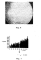
- FIG. 4 shows an image of a scratch on the surface of the glass substrate detected by the CCD 6.
- Fig. 5 is a graph obtained by performing an image process to information of the light detected by the CCD on one certain side in the width direction of the scratch by a computer via an A/D converter (analog-digital converter).
- the CCD used at that time is a CCD of the interline system (having no mechanical shutter) in which a thermoelectric cooling function is mounted and in which the number of elements is 1300 x 1030, a detecting area is 8.71 x 6.90 mm, and a saturation amount of the CCD is 20000 electrons.
- an exposing time of the CCD is set to 200 msec.
- An X axis of Fig. 5 denotes a coordinate in the width direction of the scratch.
- a Y axis denotes an intensity of the detected light.
- a unit of a scale of the X axis is a pixel.
- one pixel is 6.7 [ ⁇ m]/(50 x 0.45), namely, it corresponds to about 0.3 ⁇ m. (6.7 ⁇ m indicates a size of one pixel of the CCD.)
- the light intensity is resolved to 12 bits (4096 : 1) and one scale denotes (20000/4095) ⁇ Y(Y: scale) electrons.
- the intensity of the light leaked out of the scratch is (20000/4095)
- x 4095 20000 electrons as a peak value that exceeds a allowance value of the CCD and the intensity of light in a region other than the scratch is equal to 0.
- the ununiform portion in which the scratch or the like exists is brightly seen in a linear or a dot form in a black background.
- the ununiform portion such as a scratch can be clearly discriminated from the obtained image.
- Fig. 6 shows an image of a scratch similar to that of Fig. 4 observed by an optical microscope (reflection ⁇ bright field).
- Fig. 7 is a graph showing the image to which the image process similar to that in Fig. 5 was performed.
- signals of the scratch are buried by signals of the background and the scratch cannot be detected by the method.
- AFM atomic force microscope
- the incident angle ⁇ i of the laser beam when it is desired to confirm the incident angle ⁇ i of the laser beam to the transparent substrate 1, for example, as shown in Fig. 2, so long as an wedged optical member 8 is arranged on the substrate surface via matching oil or the like, the incident angle ⁇ i can be obtained from a refractive index ⁇ of light which is emitted from the optical member 8 or an apex angle of the optical member 8.
- the light can be also introduced from portions other than the chamfer portions (C planes) of the substrate.
- Fig. 8 shows a relation between an S/N ratio and a normalized exposing time when an arbitrary scratch is observed and the image process similar to the above is performed in order to clarify a difference between a case where the ununiformity is detected by the optical microscope in a conventional normal illumination and a case where the ununiformity is detected by the inspecting method of the present invention.
- the normalized exposing time is defined as (exposing time of the CCD)/(maximum exposing time of the CCD until the signals in the background reach (20000/4095) x 100 electrons) and the S/N ratio is set to 10 ⁇ log 10 (S/N).
- the S/N ratio exceeds 4.8 dB (the signal for the background is equal to an amount that is three times as much as that of noises) which is generally known as an image processing possible level by far, so that the presence or absence, kind, and size of the ununiformity in the transparent material can be accurately discriminated.
- the incident angle ⁇ i is set to 44.1°.
- the optimum incident angle at which the total reflection is repeated more can be easily selected by simulations shown as follows. The results obtained by simulating a situation in which the light propagates in the transparent substrate will now be explained hereinbelow.
- the dimension of the transparent substrate 1 is 152.4 x 152.4 x 6.35 mm that is the same as that of the glass substrate for the photo mask in the foregoing embodiment.
- the width of C plane is set to 0.4 mm.
- the refractive index of the transparent substrate 1 is set to 1.47 that is a refractive index of quartz glass and the refractive index around the transparent substrate 1 is set to 1.00 that is a refractive index of air.
- a vector (unit vector) indicative of the direction of the beam which impinges on the C plane (which forms an angle of 45° against the main surface and T plane) obtained by chamfering the transparent substrate 1 is set to (0.0000000, 0.6864532, -0.7271740).
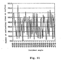
- Fig. 10 shows results of the simulations.
- the incident angle is the incident angle to the surface (main surface) on which the beam first impinges after it enters the substrate 1.
- the incident angle is changed every 0.05 degree of angle.
- Fig. 11 is a graph showing the number of reflecting times on the surfaces at respective incident angles. As will be understood from Fig. 11, it is sufficient that the incident angle at which the number of reflecting times on the surfaces increases is selected in accordance with the form or the like of the transparent substrate. It is also sufficient that the incident angle of the light which is introduced is fluctuated.
- Fig. 12 shows states of the propagation of the light in the substrate in case of the incident angle of 43.35°.
- Figs. 12(1), (2), and (3) show states in which the number of reflecting times on the surfaces are set to 50, 250, and 661 times (upon emitting), respectively.
- the propagation is performed in the only region in the cross section of one plane (yz plane). As shown in Fig. 12, it will be understood that the light beam repeats the total reflection and propagates so as to fill the region.
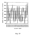
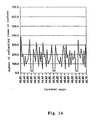
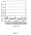
- the simulation results when the width of C plane, refractive index of the glass substrate (corresponding to the wavelength of the laser beam) in the simulation of Fig. 9 are changed are shown in Figs. 13, 14, and 15.
- the simulation is executed under the conditions similar to those of the simulation executed in Fig. 9 other than a fact that the refractive index of the glass substrate is set to 1.46 (corresponding to the wavelength of the laser beam that is equal to 543 nm) and the width of C plane is changed to 0.2 mm (Fig. 13), 0.4 mm (Fig. 14), and 0.8 mm (Fig. 15).
- the width of C plane is equal to 0.4 mm or less.
- the critical angle for satisfying the total reflecting conditions is changed by changing the refractive index (or wavelength of the laser beam (because the refractive index of the transparent substrate is decided by the wavelength of the laser beam)) of the transparent substrate, so that the number of reflecting times on the surfaces can be adjusted.
- the critical angle to satisfy the total reflecting conditions as a difference between the refractive index of the transparent substrate and that of the external medium (for example, the air) of the transparent substrate is larger, a degree of freedom of the critical angle increases. In accordance with the above, the number of reflecting times on the surfaces also increases. In fact, however, there is a case where the material of the transparent substrate is limited depending on the use.
- the number of reflecting times on the surfaces can be adjusted by properly selecting the wavelength of the laser beam.
- the wavelength of the laser beam As a wavelength of the laser beam, the wavelength in which the absorption for the transparent substrate is little is preferable. Since it is influenced on the resolution of the ununiformity, the wavelength of the laser beam is selected in consideration of the following points.
- Fig. 16 shows loci of the light beam in the general direction introduced through the transparent substrate, which is not parallel to the one side similar to the above simulation.
- a vector indicative of the direction of the light beam which impinges on the C plane of the transparent substrate 1 is set to (0.6924, 0.3823, -0.6117) and the conditions other than the above are the same as those of the simulation (Fig. 9).
- the introduced light beam repeats the total reflection in the transparent substrate 1 and is substantially confined in the substrate, so that the light propagates in the whole area of the substrate. Therefore, even when the scanning of the illuminating light is not executed at all, the whole range of the transparent substrate as an inspecting region can be inspected in a lump at a high speed.
- the case where one certain surface of the transparent material is decided as shown in the above embodiment, the incident angle satisfying the total reflecting conditions is determined in the surface, the light is introduced, and after that, the incident position of the light is moved in accordance with the form of the transparent material is more preferable than the case where three dimensional directional vectors (x, y, z) of the incident light are set so that the introduced light covers the whole region in the transparent material and the light is introduced from a certain point on the substrate, because the inspecting method can be simplified.
- the transparent material is the substrate having the surfaces which face each other, it is particularly effective.
- the inspection is executed by introducing the light from the direction of one side 1b or from two directions of the sides 1a and 1b.
- the inspection is executed by introducing the light from the two directions of the sides 1a and 1b, it is effective to detect a defect having directionality or the like and the inspection at a higher precision can be performed, so that it is preferable.
- the present invention is extremely effective with respect to the detection of the defect having directionality for the light, which can be detected because it glints in a specific irradiating direction but cannot be detected because it does not glint in the other irradiating directions, which fact is peculiar to a scratch on glass.
- the reason is as follows. Since the light is substantially confined in the inspecting object made of the transparent material by geometrically and optically repeating the total reflection, the irradiated light is deviated from an inherent orbit only in the ununiform portion of the inspecting object and leaks out of the inspecting object from the geometrical and optical viewpoints.
- the ununiform portion is illuminated from various directions in the process to repeating the total reflection.
- the defect having the directionality can be hardly detected.
- the defect of the glass in which the transmittance is the same but the refractive index alone is different which fact is peculiar to the striae of the glass, the light is deviated from the inherent orbit in a portion where the refractive index is different and leaks out of the inspecting object, so that the defect can be detected.
- the detection is impossible in principle.
- the glass substrate having the defect can be rapidly and properly excluded, so that the productivity of the glass substrate can be improved.
- the glass substrate having the defect such as a scratch on the surface, it can be formed as a glass substrate for the photo mask in a range of a specification.
- the above inspecting method is used in the inspecting process after the manufacturing process of the glass substrate as a transparent substrate for the photo mask.
- the optical ununiformity of the glass substrate can be detected at a high sensitivity and a high speed, so that there are provided ununiformity inspecting method and apparatus of a high utility.
- the incident angle is changed in a range where the total reflection may occur on the surface of the transparent material and the light is introduced in the transparent material. Consequently, even when there is a variation in dimensions of the transparent materials and the optimum total reflecting conditions for the transparent materials slightly differ, the incident light of a predetermined direction is not introduced but the light having different incident angles is introduced and propagates various - paths while being totally reflected, so that the light is spread up to the corners of the transparent material without leaking.
- an angle adjusting mechanism is provided for the laser itself or the holder for holding the substrate, or means such as an acousto-optical polariscope for fluctuating the incident angle by using the acousto-optical effect of the ultrasonic beam can be also used.
- the incident angle ⁇ i of the laser beam is successively changed in a range of 45.0° to 44.0°.
- the introduction of the laser beam to the transparent material is performed on the basis of information of the transparent material. Consequently, when a plurality of transparent materials are inspected, particularly, the inspection can be efficiently executed.
- the information of the transparent material indicates the relative positional relation between the transparent material and illuminating means, the state of the surface of the transparent material (whether it has been mirror-polished), or the like.
- the information regarding the relative positional relation between the transparent material and the illuminating means is necessary to properly introduce the light from the illuminating means into a predetermined position of the transparent material.
- the information regarding the surface state of the transparent material can be used when such a substrate is previously eliminated (as necessary, it is returned to the preceding process (polishing or the like)).
- the position detecting means indicates a distance measuring device (laser scan measuring system, laser interference measuring device, or the like) by using the laser beam.
- the transmitting means indicates a computer for fetching data from the position detecting means and feeding back to the illuminating means, the angle adjusting means, moving means for moving the incident position of the introduction light, and the like. It is also sufficient to provide an apparatus such as TV camera or CCD image pickup device image sensor for observing the surface state of the transparent material and, for example, eliminating the inspecting object, for example, which is not mirror-polished.
- the relation (information) between the presence or absence, kind (scratch or crack of the surface portion, internal striae or foreign matter), and size (area, length, width, depth, region, or the like) of the ununiformity previously existing in the transparent material and the information of the light which leaks out of the surface (light amount, luminance, intensity distribution, depth from the surface of the leak light) has been stored in the computer or the like.
- the presence or absence, kind, and size of the ununiformity of the transparent material can be discriminated.
- a desired transparent material can be immediately extracted.
- the glass substrate having the ununiformity which has an influence on the time of formation of the pattern or the exposure for a transferring object can be eliminated before the next process after the inspection or can be also returned to the re-polishing process, so that the productivity can be improved.
- the discriminating method will now be specifically explained by using the inspecting apparatus in Fig. 1.
- the light leaked out of the substrate 1 is formed as an image on the surface of the CCD 6 of the CCD camera by the lens system 7.
- the shutter of the CCD camera is opened as it is and image data of the whole surface of the main surface of the substrate 1 is accumulated.
- the image data fetched in the CCD camera is converted to a digital signal by the A/D converter 11, the converted signal is inputted to the image processing apparatus 12 and is stored into the storage unit, and an image analysis is performed by the discriminating unit.
- the discriminating unit by comparing the image data of the light detected by the inspection with basic data of the image information which has previously been inputted in the storage unit, the presence or absence, kind, and size of the transparent substrate 1 are discriminated.
- the moving amount (information of the irradiating position of the substrate 1) of the table 5 or the like is inputted from a laser interferometer (not shown) or the like to the image processing apparatus 12. From the image data of the CCD camera and position data of the substrate 1, which kind and size of ununiform portion exists on which position (x, y) of the substrate 1 is obtained.
- the ununiform portion exists in the irradiating region of the substrate 1, the ununiform portion (and its periphery) is brightly seen in a dot form.
- images as shown in Fig. 17 are observed (the images in Fig. 17 are shown by reversing bright and dark of images that are actually observed).
- a linear image 41 as shown in Fig. 17(a) is a scratch on the surface of the substrate 1.
- the length is 30 ⁇ m
- the width is 0.2 ⁇ m
- the depth is 0.002 ⁇ m (the size of such a fine scratch was measured by the atomic force microscope).
- the 17(b) are caused by striae or foreign matters such as gasses in the substrate 1.
- the diameter is about 1 mm.
- the pattern or size of the image differs depending on the ununiformity existing in the substrate 1, the kind of ununiformity can be discriminated.
- the images 42 by the striae are seen so as to glimmer as compared with the image 41 by the scratch, it can be also discriminated from the luminance or intensity distribution of the image.
- the size of the ununiform portion can be discriminated from a light amount of the detected light. Further, whether the position where the ununiformity exists is located on the surface portion of the substrate 1 (scratch or crack) or in the substrate 1 (striae or foreign matter) can be discriminated from a location (depth) where a focal point is obtained by focusing on bright dotty portions of the substrate 1 by the optical microscope. As for the inspection of the ununiformity, in order to realize a high speed process, it is desirable that whether the bright dotty leak light exists on the surface of the substrate 1 is first inspected and, with respect to only the substrate 1 in which the leak light was detected, bright dotty portions is further inspected by enlarging or the like by the optical microscope.
- a laser beam L1 is introduced in the direction (X direction) of the side 1a of the transparent substrate 1 and a laser beam L2 is introduced in the direction (Y direction) of the side 1b at the same time or it is also sufficient that the laser beams of the different directions are introduced every direction (X and Y directions or the like) to the substrate 1, thereby inspecting.
- the ununiformity is inspected by introducing a laser beam L from the corner portion of the transparent substrate 1 by using, for example, a laser 13 and mirrors 14 and 15, the kind and size of the ununiformity can be discriminated by an image forming optical system 16, a CCD camera 17, and an image processing apparatus 18 in a manner similar to the above.
- the introduction of the laser beam to the transparent substrate has been performed from the chamfer portion as a C plane in the above embodiment, it is also possible to introduce the beam from planes other than the chamfer portions.
- an optical member made of a material having substantially the same refractive index as that of the transparent substrate is attached by an adhesive agent or the like.
- the chamfer portion is mirror-polished. As the width of chamfer portion is smaller, it is more desirable. It is better to set the width to be equal to 0.4 mm or less, more preferably, 0.2 mm or less. Even if it is set to be extremely small (smaller than 0.1 mm), since a defect occurs upon mirror-polishing, it is not preferable.
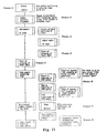
- Fig. 21 is a diagram showing a flowchart for the inspecting process to selecting the transparent substrate.
- a transparent substrate 1 serving as an inspecting target a glass substrate for a photo mask made of quartz glass in which both main surfaces, end surfaces, and chamfer surfaces are mirror-polished, whose size is 152.4 x 152.4 x 6.35 mm, and in which the width of each C plane is equal to 0.4 mm is prepared.
- the glass substrate is conveyed by conveying means (not shown) until it is come into contact with a stage guide pin (not shown) fixed to a certain reference position of the inspecting apparatus, thereby positioning the glass substrate (process 1). At that time, an origin and coordinates in the glass substrate are decided.
- the inspecting region is specified on the basis of the previously decided coordinates.
- the inspecting region does not always coincide with a measuring visual field of the CCD. Therefore, when they don't coincide with each other, the measuring region is divided into (A1, A2, A3, B1, B2, B3, ...) in correspondence to the visual field of the CCD (Fig. 22) (process 2).
- the divided measuring regions A1, A2, A3, B1, B2, B3, ... coincide with the measuring visual field of the CCD.
- the CCD used for the measurement is the CCD of the interline system (having no mechanical shutter) having a thermoelectric cooling function is mounted, in which the number of elements is 1300 x 1035 and a detecting area is 8.71 x 6.90 mm.
- the measuring visual field is measured at a magnification of 0.7 time.
- the incident position and the incident angle of the laser beam are adjusted so that the laser beam propagates in the inspecting area (process 3).
- the incident position and incident angle of the laser beam information of the glass substrate is obtained by position detecting means (not shown) for detecting the relative positional relation between the transparent substrate and the laser and the laser beam is introduced by adjusting the mirrors and table so that the laser beam can be accurately introduced through the glass substrates having different sizes.
- the incident angle since the refractive index of the glass substrate is 1.46 and the critical angle ⁇ c is about 43.2°, the incident angle ⁇ i is set to 45.0°.
- the incident angle of the laser beam is fluctuated in a range where the beam repeats the total reflection and propagates (process 4).
- the process is executed in order to absorb the variation of processing precisions of the glass substrate and inspect the ununiformity of the glass substrate. The process is also executed for an image matching of the CCD in the next process.
- means for fluctuating the incident angle means having a function for automatically adjusting the angle of the mirror by a control of a computer or the like or means such as an acousto-optical polariscope for fluctuating the incident angle by using the acousto-optical effect of the ultrasonic beam can be also used.
- the incident angle ⁇ i is successively changed in a range of 45.0° to 44.0° so as to satisfy the total reflection.
- the focusing of the CCD image is executed (process 5).
- the focusing is executed by integratedly moving the laser and the mirrors in an a axial direction (direction to the lens and CCD). It is also sufficient that the glass substrate, mirrors, and laser are fixed and the lens and CCD are integratedly moved in a z axial direction.
- the laser beam L is introduced from the chamfer plane serving as an introducing surface so that the laser beam L which passes certain coordinates (A1X1, A1Y1) of the measuring region A1 as one of the divided regions and is parallel to the y axial direction propagates, the incident angle is changed in a range where the laser beam repeats the total reflection and propagates in the glass substrate (of 45.0° to 44.0°), thereby inspecting the ununiformity.
- the similar scan is performed so that the laser beam L is moved in the x axial direction, the inspection of the ununiformity is performed until the laser beam passes coordinates (A1XX, A1Y1) at the end portion of the measuring region A1, so that the inspection of the ununiformity in the measuring region A1 is finished (process 6).
- the exposure of the CCD is executed from the start to the completion of the inspection of the ununiformity in the measuring region A1.
- the laser beam is impinged so that the laser beam which passes (A1X1, A1Y1) and is parallel to the x axial direction propagates and it is moved in the y axial direction.
- information (analog signal) of the light which was detected by the CCD and which leaked out of the glass substrate is converted into a digital signal by the A/D converter in order to execute an image process by information accumulating means such as a computer.
- the information of the light converted into the digital signal is accumulated by the information accumulating means such as a computer, the intensity of the light as shown in Fig. 28 is resolved to 12 bits (4096 : 1), and the image process is performed (process 7).
- the Y axis in Fig. 23 denotes the intensity of the light and one scale denotes (20000/4095) ⁇ Y(Y:scale) electrons.
- the ununiformity existing in the glass substrate is discriminated as a scratch on the substrate surface.
- x 200 electrons which has previously been set as an allowance design value of the scratch (when the background is (20000/4095) x 100 electrons or less), since it exceeds the allowance design value, it is discriminated that the glass substrate is bad (process 8).
- the inspection for the ununiformity is not executed in the next inspecting area A2 but the process is shifted to the re-polishing and cleaning process for the substrate.
- the previously divided inspecting regions A2, A3, B1, B2, ... and the processes 6 to 8 are repetitively executed.
- the glass substrate for the photo mask is selected as good.
- the glass substrate having the defect can be rapidly and properly eliminated, so that the producibility of the glass substrate can be improved.
- the glass substrate having the defect By again precisely mirror-polishing and cleaning the glass substrate having the defect, it can be formed as a glass substrate for the photo mask which lies in the range of the specification.
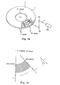
- Fig. 24 is the second example in which the method of selecting the transparent substrate using the method according to the invention is applied to a glass substrate for a magnetic disk.
- a disc-shaped glass substrate for magnetic disk made of quartz glass in which both main surfaces (H), inner rim edge surface (T1 plane) and outer rim edge surface (T2 plane), and chamfer surfaces (C planes) are mirror-polished and in which the diameter is 95 mm (3.5 inches ⁇ ), the thickness is 0.8 mm, and a diameter of a circular hole on a center portion is 20 mm ⁇ is prepared.
- the region on the main surface of the transparent substrate is divided into the measuring regions A1, A2, A3, ... from the inner rim side to the outer rim side.
- the inspection regarding the ununiformity is executed every divided measuring region.
- the inspection for the ununiformity is executed in such a manner that the laser beam L is introduced from the outer rim edge surface of the disc-shaped glass substrate 1 in the direction of the center (O) of the disc, the light is confined in one plane in the radial direction (r direction) including the outer rim edge surface and the inner rim edge surface (so that the total reflection is repeated in both the main surfaces of the transparent substrate and the light is returned between the inner rim and outer rim edge surfaces), the disc is rotated by a driving apparatus (not shown) for rotating the disc, and the laser beam L is moved in the direction to the rim ( ⁇ direction) of the disc.
- a driving apparatus not shown
- the laser beam L is introduced to the chamfer surface (C plane) as an introducing surface by a laser 25 and mirrors 26 and 27 so that the laser beam L which passes certain coordinates (A1r1, A1 ⁇ 1) of the measuring region A1 divided as shown in Fig. 25 and is parallel to the r direction is propagated, the incident angle is changed in a range (45.0 ° to 44.0°) where the beam repeats the total reflection and propagates in the disc-shaped glass substrate 1, thereby inspecting the ununiformity.
- the disc-shaped glass substrate 1 is rotated, the same scan is performed by moving the laser beam in the ⁇ direction, and when the inspection for the ununiformity in the region which passes the coordinates (A1r1, A1 ⁇ X) of the measuring region A1 is finished, the inspection of the ununiformity in the measuring region A1 is completed.
- the laser beam is impinged from the inner rim edge surface of the disc or from both of the inner rim and outer rim edge surfaces.
- the image process and allowance discrimination for the ununiformity are executed. Consequently, since the defect exceeding the allowance range is not found in the inspecting region A1, the inspecting region is changed to the inspecting regions A2, A3, B1, B2, ... and the inspection for the ununiformity similar to that in the inspecting region A1 is executed. Although the inspection for the ununiformity is performed in the whole region of the disc-shaped glass substrate, no defect exceeding the allowance range is found, so that it is discriminated as good.
- the scattering light can be eliminated by applying a (color) filter for absorbing or reflecting a wavelength area of the mixed light between the transparent material and the detecting means.
- the light having the specific polarization the light becomes light having peculiar polarizing characteristics in a peculiar polarizing state by the Rayleigh scattering.
- a polarizing device such as polar screen, polarizing plate, or polarizing prism is placed between the transparent material and the detecting means, so that the Rayleigh scattering light can be effectively eliminated.
- the introduction light is reduced in correspondence to the size of the introducing surface of the transparent material on which the laser beam is impinged by converging the beam by the optical system such as a lens and the introducing surface is shaped into a concave cross section so that the converged laser beam is introduced as almost parallel light into the transparent material from the introducing surface. Consequently, the stray light can be reduced, the contrast of the detection light for the ununiformity can be increased, and the detection can be executed at a high sensitivity and a high precision.
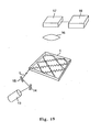
- Fig. 26 As another factor to reduce the contrast of the light which leaks out of the ununiformity (defect) of the transparent material, as shown in Fig. 26 (in the diagram, (1) is a perspective view and (2) is a cross sectional view), there is a case where the light shielding material is a rectangular plate having main surfaces, end surfaces, and chamfer surfaces, when the ununiformity is inspected by introducing the laser beam L from the introducing surface (chamfer surface(C plane)), the light leaks out of the chamfer surfaces other than the introducing surface and becomes stray light.
- the light shielding material is a rectangular plate having main surfaces, end surfaces, and chamfer surfaces
- portions between the chamfer surfaces other than the chamfer surface which face each other in the progressing direction of the light to introduce the light are connected by an introducing light 50 formed by binding a plurality of optical fibers arranged in the surface direction of the chamfer surfaces, thereby enabling the light which leaks out of the chamfer surfaces to be again introduced through the transparent material. Therefore, the stray light is reduced, the introduced laser beam can be more effectively concentrated to the ununiform portion, so that the contrast is increased and the detection can be realized at a high sensitivity and a high speed.
- the transparent substrate made of glass has been mentioned as a transparent material having the mirror-polished surfaces. It is not limited to glass but any material, for example, optical plastic such as acrylic resin or optical crystal such as quartz through which the inspection light can transmit can be used.
- the example in which the whole surface of the transparent substrate was mirror-polished has been mentioned. It is not limited to the above but a transparent substrate having a part or whole of the surface which is not mirror-polished can be also used.
- a transparent substrate having a part or whole of the surface which is not mirror-polished can be also used.
- the glass substrate as a glass substrate for the photo mask there is a case where the end surfaces other than the main surfaces, in which the pattern is not formed, are not mirror-polished.
- the glass substrate for the magnetic disk there is a case where the inner rim and outer rim edge surfaces in which a film such as a magnetic layer is not formed are not mirror-finished.
- the surfaces look as if they are mirror-polished (free surface of liquid, pseudo mirror surface), so that the ununiform portion can be inspected by the inspecting method of the invention. More particularly, when it is desired that the ununiform portion alone (striae, bubbles, foreign matter, or the like) existing in the transparent material is inspected at a stage where the mirror-finishing is not executed, it is effective.
- a liquid such as a matching oil
- a matching oil or a sealing agent used for optical parts, or masking agent for scratch of the glass can be mentioned.
- the liquid coated on the surface of the transparent substrate can be in a liquid state as it is or in a solid state of jelly, a hard film, or the like after completion of the coating.
- any method such as brush coating (a brush or a sponge-like material is soaked in liquid, thereby coating), spray coating, or spin coating which can smoothly coat on the surface of the transparent material can be used. In this case, the proper method is selected in accordance with the liquid which is used or coating surface.
- the liquid-coated surface in a mirror state optically and substantially becomes the surface of the transparent material, so that the light introduced through the transparent material can be certainly totally reflected and be returned into the inside.
- quartz glass reffractive index is 1.466
- quartz glass refractive index is 1.466
- Enterannew trade name, refractive index is 1.49
- diiodemethane ethylene iodide
- refractive index is 1.74
- cedar oil reffractive index is 1.52
- liquid paraffin refractive index is 1.48
- Aquatex trade name, refractive index is 1.4
- glycerol reffractive index is 1.46
- the refractive index and viscosity can be adjusted by adding organic solution such as xylene.
- a water soluble material such as glycerol or Aquatex
- the refractive index and viscosity can be adjusted by adding water.
- a masking agent for scratch of the glass there is emulsion composition in which polyorganosiloxane and polydiorganosiloxane are main components disclosed in Japanese Patent Application Laid-Open Publication No. 6-4496 (1994) or the like.
- the ununiformity alone striae, bubbles, foreign matter, or the like
- the ununiform portion exists in the inside, it results in fatal defect.
- the glass substrate for a phase shift mask since the bad one can be eliminated by inspecting at a stage before the mirror-finishing, the costs of manufacturing can be also held down.
- the form of the transparent material is not limited to the square (rectangular) or circular substrate but the transparent material can take any form of a block form, a sphere, a column, a cylinder, a polyhedron, and a form having curved surfaces.
- the transparent material can take any form of a block form, a sphere, a column, a cylinder, a polyhedron, and a form having curved surfaces.
- a substrate having surfaces which face each other more particularly, a substrate having at least two pairs of parallel planes which face each other (for example, square (rectangular) or circular cone) is used as such an above-mentioned transparent material
- the introduced light repeats the total reflection and easily enters a state in which the light is confined in the substrate.
- the inspection for the wide region of the transparent material can be simultaneously executed and the inspection can be executed at a high speed.
- the inspection can be applied to various kinds of substrates such as glass substrate for the electronic device (for the photo mask (phase shift mask)), glass substrate for the liquid crystal display, or glass substrate for information recording (such as magnetic disk or optical disk) Since the glass substrate for information recording is disc-shaped, in case of actually inspecting, the laser beam is impinged from the polished outer rim or inner rim edge surface (for example, chamfer portion).
- the detecting means are provided on the upper and lower sides of the substrate, respectively, and both of the substrate surfaces are inspected in a lump.
- the gas laser has been used as a laser. It is not limited to the above but a laser of a visible area such as a semiconductor laser or, so long as it is absorbed to the transparent substrate by little, an excimer laser of an ultraviolet area, an Nd-YAG laser of an infrared area, a CO 2 laser, or the like can be used as a light source for the inspection. Particularly, in case of using the laser of the ultraviolet area (for example, a higher harmonic wave of the excimer laser, a YAG laser, or the like), since the foreign matter or the like adhered on the substrate surface can be eliminated due to the operation such as evaporating or transpiring, it is preferable.
- the laser of the ultraviolet area for example, a higher harmonic wave of the excimer laser, a YAG laser, or the like
- the foreign matter or the like adhered on the substrate surface can be eliminated due to the operation such as evaporating or transpiring, it is preferable.
- the angle adjusting means for changing the incident angle for the substrate was attached to the mirrors located between the laser and the substrate. So long as the incident angle of the laser beam for the substrate can be changed, any construction can be used. It is also sufficient that the angle adjusting means is provided for the laser itself or it is provided for the holder for supporting the substrate. As for the introduction of the laser beam, it is also sufficient that the light is introduced by using not mirrors but an optical fiber. At that time, it is sufficient that an emitting edge portion of the optical fiber is moved along each side of the substrate by using a guide or the like or an fluctuation is applied to the side of the emitting edge portion of the optical fiber, thereby fluctuating the incident angle.
- the laser beam is confined in the transparent material by using the total reflection as a physical critical phenomenon
- the responses to the inspection light in the ununiform and uniform portions of the transparent material become critical and the ununiformity appears as a very clear contrast, so that the ununiformity such as a fine scratch can be detected at a high sensitivity and it can be also detected at a high precision and a high speed.
- the defect such as internal damage or striae can be also detected.
- the presence or absence, kind, and size of the ununiformity of the transparent material are discriminated on the basis of the information of the light leaked out of the surface of the transparent material, so that a desired transparent material can be immediately extracted and the producibility of the transparent material can be improved.
Claims (15)
- Verfahren zum Untersuchen einer Ungleichmäßigkeit eines transparenten Materials, wobei
ein Laserstrahl in das transparente Material (1) eingeleitet wird, das transparente Material mindestens ein Paar totalreflektierender Flächen (H), die einander gegenüberstehen und an denen der in das transparente Material eingeleitete Laserstrahl eine Totalreflexion wiederholt, wodurch er sich in dem transparenten Material in Ausbreitungsrichtung ausbreitet, und mindestens ein Paar von Wendeflächen (T), die so angeordnet sind, dass sie einander in Ausbreitungsrichtung gegenüberstehen, aufweist, wobei
Licht, das aus den totalreflektierenden Flächen (H) und/oder den Wendeflächen (T) entweicht, wenn ein ungleichmäßiger Abschnitt in dem optischen Weg des Laserstrahls in dem transparenten Material existiert, erfasst wird,
dadurch gekennzeichnet, dass
der Laserstrahl unter einem solchen Winkel in das transparente Material eingeleitet wird, dass er sich, wenn der optische Weg des Laserstrahls in dem transparenten Material optisch gleichmäßig ist, in dem transparenten Material ausbreitet und auf die totalreflektierenden Flächen (H) und die Wendeflächen (T) fällt, so dass er sowohl an den reflektierenden Flächen als auch an den Wendeflächen totalreflektiert wird, und zwischen dem mindestens einen Paar von Wendeflächen wiederholt wird, wodurch er im Untersuchungsbereich verbreitert wird, der durch die Ausbreitung gebildet ist und von den totalreflektierenden Flächen und den Wendeflächen umgeben ist. - Verfahren zum Untersuchen der Ungleichmäßigkeit des transparenten Materials (1) nach Anspruch 1,
dadurch gekennzeichnet, dass
wenn angenommen wird, dass der Brechungsindex des transparenten Materials (1) für eine Wellenlänge λ des eingeleiteten Laserstrahls auf nt gelegt ist, der Brechungsindex des externen Mediums, das in Kontakt mit dem transparenten Material (1) gelangt, auf ni gelegt ist, und der Winkel des auf die totalreflektierenden Flächen und die Wendeflächen einfallenden Lichts auf ik gelegt ist, wobei k die Position bezeichnet, an der der Laserstrahl auf die totalreflektierenden Flächen und die Wendeflächen fällt, nachdem der Laserstrahl in das transparente Material (1) eingeleitet wurde, und die Einfallspositionen nacheinander als k = 1, 2, ... festgelegt sind, der Laserstrahl so eingeleitet wird, dass ik an den totalreflektierenden Flächen und den Wendeflächen größer oder gleich einem durch sin = ni/nt ausgedrückten kritischen Winkel ist. - Verfahren zum Untersuchen der Ungleichmäßigkeit des transparenten Materials (1) nach einem der Ansprüche 1 bis 2, dadurch gekennzeichnet, dass eine Einleitfläche zum Einleiten des Laserstrahls in einem Abschnitt bereitgestellt ist, der zwischen einer der totalreflektierenden Flächen und mindestens einer der Wendeflächen sandwichförmig angeordnet ist.
- Verfahren zum Untersuchen der Ungleichmäßigkeit des transparenten Materials (1) nach Anspruch 3, dadurch gekennzeichnet, dass zumindest die Einleitfläche spiegelpoliert ist.
- Verfahren zum Untersuchen der Ungleichmäßigkeit des transparenten Materials (1) nach einem der Ansprüche 3 bis 4,
dadurch gekennzeichnet, dass
wenn angenommen wird, dass die Größe der totalreflektierenden Fläche auf L gelegt ist, die Breite der Einleitfläche auf d gelegt ist, der Brechungsindex des transparenten Materials (1) für die Wellenlänge λ des Laserstrahls auf nt gelegt ist, der Brechungsindex des externen Mediums, das in Kontakt mit dem transparenten Material (1) gelangt, auf ni gelegt ist, der Strahldurchmesser des Laserstrahls auf gelegt ist, der Winkel des auf die totalreflektierenden Flächen und die Wendeflächen einfallenden Lichts auf ik gelegt ist, wobei k die Position bezeichnet, an der der Laserstrahl auf die totalreflektierenden Flächen und die Wendeflächen fällt, nachdem er in das transparente Material (1) eingeleitet wurde, und die Einfallsposition nacheinander als k = 1, 2, ... festgelegt wird, insbesondere ein Winkel des Lichts, unter dem der Laserstrahl zuerst auf die totalreflektierenden Flächen oder die Wendeflächen trifft, nachdem er eingeleitet wurde, auf 1 gelegt ist, die Anzahl der Reflexionen an den totalreflektierenden Flächen auf m gelegt ist und m durch eine Funktion ausgedrückt ist, bei der L, d, nt(λ), ni, und 1 verwendet werden, die Bedingungen für mindestens eines von L, d, nt(λ), ni, und 1 so festgelegt werden, dass m größer oder gleich einem Referenzwert in einem Bereich ist, in dem alle ik größer oder gleich dem kritischen Winkel sind, wobei der Laserstrahl entsprechend den festgelegten Bedingungen von der Einleitfläche eingeleitet wird. - Verfahren zum Untersuchen der Ungleichmäßigkeit des transparenten Materials (1) nach einem der Ansprüche 1 bis 5, dadurch gekennzeichnet, dass die totalreflektierenden Flächen und die Wendeflächen eine solche Beziehung aufweisen, dass sie einander unter rechten Winkeln kreuzen.
- Verfahren zum Untersuchen der Ungleichmäßigkeit des transparenten Materials (1) nach einem der Ansprüche 1 bis 6,
dadurch gekennzeichnet, dass
in dem Untersuchungsbereich des transparenten Materials (1), der durch das eine Paar der totalreflektierenden Flächen und das eine Paar der Wendeflächen sandwichförmig eingeschlossen ist, die Ungleichmäßigkeit auf einer bestimmten Ebene in dem durch die Ausbreitung des Laserstrahls in dem transparenten Material (1) mit Licht gefüllten Untersuchungsbereich untersucht wird und anschließend die untersuchte Ebene entlang einer Seite des transparenten Materials relativ bewegt wird, wodurch die Ungleichmäßigkeit des Untersuchungsbereichs untersucht wird. - Verfahren zum Untersuchen der Ungleichmäßigkeit des transparenten Materials (1) nach Anspruch 1,
dadurch gekennzeichnet, dass
die Oberfläche des transparenten Materials (1) aufweist: mindestens ein Paar von Hauptflächen, die zueinander parallel sind, die totalreflektierenden Flächen; mindestens ein Paar von Endflächen, die die Hauptflächen unter rechten Winkeln kreuzen, die Wendeflächen; und abgeschrägte Abschnitte, die durch die Hauptflächen und die Endflächen sandwichförmig eingeschlossen sind, die Einleitflächen. - Verfahren zum Untersuchen der Ungleichmäßigkeit des transparenten Materials (1) nach Anspruch 8, dadurch gekennzeichnet, dass der Laserstrahl so eingeleitet wird, dass der eingeleitete Laserstrahl nur in die abgeschrägten Abschnitte emittiert wird.
- Verfahren zum Untersuchen der Ungleichmäßigkeit des transparenten Materials (1) nach Anspruch 8,
dadurch gekennzeichnet, dass
wenn angenommen wird, dass der Brechungsindex des transparenten Materials (1) für eine Wellenlänge λ des eingeleiteten Laserstrahls auf nt gelegt ist, der Brechungsindex des externen Mediums, das in Kontakt mit dem transparenten Material (1) gelangt, auf ni gelegt ist und der Winkel des auf die Hauptflächen fallenden Lichts, auf die der Laserstrahl zuerst einfällt, nachdem er in das transparente Material (1) eingefallen ist, auf 1 gelegt ist, der Laserstrahl so eingeleitet wird, dass 1 in den Hauptflächen größer oder gleich einem durch sin = ni / nt ausgedrückten kritischen Winkel ist und (90° - 1) in den Endflächen größer oder gleich dem durch die vorstehende Gleichung ausgedrückten kritischen Winkel ist. - Verfahren zum Untersuchen der Ungleichmäßigkeit des transparenten Materials (1) nach einem der Ansprüche 8 bis 10, dadurch gekennzeichnet, dass zumindest die abgeschrägten Abschnitte spiegelpoliert sind.
- Verfahren zum Untersuchen der Ungleichmäßigkeit des transparenten Materials (1) nach Anspruch 11, dadurch gekennzeichnet, dass die gesamte Oberfläche des transparenten Materials (1) spiegelpoliert ist.
- Verfahren zum Untersuchen der Ungleichmäßigkeit des transparenten Materials (1) nach einem der Ansprüche 8 bis 12,
dadurch gekennzeichnet, dass
in dem Untersuchungsbereich des transparenten Materials (1), der sandwichförmig durch das eine Paar der Hauptflächen und das eine Paar der Endflächen eingeschlossen ist, die Ungleichmäßigkeit auf einer bestimmten Ebene in dem durch die Ausbreitung des Laserstrahls in dem transparenten Material (1) mit Licht gefüllten Untersuchungsbereich untersucht wird und anschließend die untersuchte Ebene entlang einer Seite des transparenten Materials (1) relativ bewegt wird, wodurch die Ungleichmäßigkeit des Untersuchungsbereichs untersucht wird. - Verfahren zum Untersuchen der Ungleichmäßigkeit des transparenten Materials (1) nach einem der Ansprüche 1 bis 13, dadurch gekennzeichnet, dass das transparente Material (1) Glas ist.
- Verfahren zum Untersuchen der Ungleichmäßigkeit des transparenten Materials (1) nach Anspruch 14, dadurch gekennzeichnet, dass das transparente Material (1) ein Glassubstrat für eine elektronische Vorrichtung oder ein Glassubstrat für ein Informationsaufzeichnungsmedium ist.
Priority Applications (1)
| Application Number | Priority Date | Filing Date | Title |
|---|---|---|---|
| EP04029568A EP1526375B1 (de) | 1997-07-17 | 1998-07-16 | Vorrichtung zur Inspektion eines transparenten Materials im Hinblick auf Unregelmässigkeiten |
Applications Claiming Priority (9)
| Application Number | Priority Date | Filing Date | Title |
|---|---|---|---|
| JP19276397 | 1997-07-17 | ||
| JP19276397 | 1997-07-17 | ||
| JP26345697 | 1997-09-29 | ||
| JP26345697 | 1997-09-29 | ||
| JP29872797 | 1997-10-30 | ||
| JP29872797 | 1997-10-30 | ||
| JP36033197 | 1997-12-26 | ||
| JP36033197 | 1997-12-26 | ||
| PCT/JP1998/003200 WO1999004249A1 (fr) | 1997-07-17 | 1998-07-16 | Procede de verification de l'inegalite d'une substance emettrice de lumiere, dispositif concu a cet effet, et procede de triage de substrats transparents |
Related Child Applications (1)
| Application Number | Title | Priority Date | Filing Date |
|---|---|---|---|
| EP04029568A Division EP1526375B1 (de) | 1997-07-17 | 1998-07-16 | Vorrichtung zur Inspektion eines transparenten Materials im Hinblick auf Unregelmässigkeiten |
Publications (3)
| Publication Number | Publication Date |
|---|---|
| EP0927883A1 EP0927883A1 (de) | 1999-07-07 |
| EP0927883A4 EP0927883A4 (de) | 2002-03-27 |
| EP0927883B1 true EP0927883B1 (de) | 2005-09-28 |
Family
ID=27475609
Family Applications (2)
| Application Number | Title | Priority Date | Filing Date |
|---|---|---|---|
| EP98932551A Expired - Lifetime EP0927883B1 (de) | 1997-07-17 | 1998-07-16 | Verfahren zum untersuchen einer ungleichmässigkeit eines transparenten materials |
| EP04029568A Expired - Lifetime EP1526375B1 (de) | 1997-07-17 | 1998-07-16 | Vorrichtung zur Inspektion eines transparenten Materials im Hinblick auf Unregelmässigkeiten |
Family Applications After (1)
| Application Number | Title | Priority Date | Filing Date |
|---|---|---|---|
| EP04029568A Expired - Lifetime EP1526375B1 (de) | 1997-07-17 | 1998-07-16 | Vorrichtung zur Inspektion eines transparenten Materials im Hinblick auf Unregelmässigkeiten |
Country Status (6)
| Country | Link |
|---|---|
| US (2) | US6610994B1 (de) |
| EP (2) | EP0927883B1 (de) |
| KR (1) | KR100606460B1 (de) |
| DE (2) | DE69833580T2 (de) |
| TW (1) | TW396274B (de) |
| WO (1) | WO1999004249A1 (de) |
Families Citing this family (33)
| Publication number | Priority date | Publication date | Assignee | Title |
|---|---|---|---|---|
| EP0927883B1 (de) | 1997-07-17 | 2005-09-28 | Hoya Corporation | Verfahren zum untersuchen einer ungleichmässigkeit eines transparenten materials |
| JP4074977B2 (ja) * | 2001-02-02 | 2008-04-16 | ミネベア株式会社 | 面状照明装置 |
| TWI243258B (en) * | 2002-11-29 | 2005-11-11 | Hon Hai Prec Ind Co Ltd | Measurement apparatus of light guide plate |
| DE10261323B3 (de) * | 2002-12-27 | 2004-10-07 | Infineon Technologies Ag | Vorrichtung und Verfahren zur Bestimmung struktureller und/oder geometrischer Eigenschaften eines Maskenblanks |
| KR100556141B1 (ko) * | 2003-03-27 | 2006-03-03 | 호야 가부시키가이샤 | 마스크 블랭크용 유리 기판 제조 방법 및 마스크 블랭크제조 방법 |
| DE10351254A1 (de) * | 2003-11-03 | 2005-06-02 | Adc Automotive Distance Control Systems Gmbh | Vorrichtung zur Erfassung von Verschmutzungen auf einer lichtdurchlässigen Abdeckscheibe vor einem optischen Einheit |
| JP2006119270A (ja) * | 2004-10-20 | 2006-05-11 | Sharp Corp | 表示装置用基板 |
| US7898650B2 (en) * | 2005-02-18 | 2011-03-01 | Hoya Corporation | Inspection method for transparent article |
| DE102005022271B3 (de) | 2005-05-10 | 2006-08-17 | Schott Ag | Verfahren und Vorrichtung zum Detektieren von Blasen in einem Glaskörper sowie zur Herstellung von Glaskörpern |
| JP4683416B2 (ja) * | 2005-06-10 | 2011-05-18 | Hoya株式会社 | マスクブランク用ガラス基板の欠陥検査方法、マスクブランク用ガラス基板、マスクブランク、露光用マスク、マスクブランク用ガラス基板の製造方法、マスクブランクの製造方法、及び露光用マスクの製造方法 |
| US7927440B2 (en) * | 2005-11-30 | 2011-04-19 | Seiko Instruments Inc. | Bonding method and method of manufacturing a display device |
| US20080045146A1 (en) * | 2006-01-18 | 2008-02-21 | Per Wahlberg | Systems and methods for establishing modular and flexible satellite communications networks |
| US8078141B2 (en) * | 2006-01-18 | 2011-12-13 | Overhorizon (Cyprus) Plc | Systems and methods for collecting and processing satellite communications network usage information |
| US8326217B2 (en) * | 2006-01-18 | 2012-12-04 | Overhorizon (Cyprus) Plc | Systems and methods for satellite communications with mobile terrestrial terminals |
| US7962134B2 (en) * | 2006-01-18 | 2011-06-14 | M.N.C. Microsat Networks (Cyprus) Limited | Systems and methods for communicating with satellites via non-compliant antennas |
| JP4878907B2 (ja) * | 2006-05-08 | 2012-02-15 | 三菱電機株式会社 | 画像検査装置およびこの画像検査装置を用いた画像検査方法 |
| JP4768543B2 (ja) * | 2006-08-09 | 2011-09-07 | 株式会社東芝 | 電子機器 |
| US8050628B2 (en) * | 2007-07-17 | 2011-11-01 | M.N.C. Microsat Networks (Cyprus) Limited | Systems and methods for mitigating radio relay link interference in mobile satellite communications |
| CN101382502B (zh) * | 2007-09-07 | 2011-07-27 | 鸿富锦精密工业(深圳)有限公司 | 表面污点检测系统及其检测方法 |
| WO2009069074A1 (en) * | 2007-11-29 | 2009-06-04 | Nxp B.V. | Method of and device for determining the distance between an integrated circuit and a substrate |
| DE102009050711A1 (de) * | 2009-10-26 | 2011-05-05 | Schott Ag | Verfahren und Vorrichtung zur Detektion von Rissen in Halbleitersubstraten |
| WO2011138297A1 (en) * | 2010-05-04 | 2011-11-10 | Sanofi-Aventis Deutschland Gmbh | Device and method for detection of defects in vitreous bodies |
| KR101233687B1 (ko) * | 2010-10-28 | 2013-02-15 | 삼성디스플레이 주식회사 | 유리 기판 식각 장치 |
| KR101112710B1 (ko) * | 2011-03-17 | 2012-03-15 | 주식회사 아이스피 | 패널부재의 외관 검사장치, 및 이를 이용한 패널부재의 외관 검사방법 |
| CN103105403A (zh) * | 2013-01-21 | 2013-05-15 | 合肥知常光电科技有限公司 | 透明光学元件表面缺陷的检测方法及装置 |
| CH709474A1 (fr) * | 2014-04-07 | 2015-10-15 | Suisse Electronique Microtech | Dispositif pour la détection de défauts dans des pièces transparentes. |
| CN105158269B (zh) * | 2015-09-29 | 2018-07-13 | 中国科学院上海光学精密机械研究所 | 大口径平面光学元件疵病三维快速暗场检测装置和方法 |
| US10957035B2 (en) * | 2018-11-30 | 2021-03-23 | Kla Corporation | Defect classification by fitting optical signals to a point-spread function |
| KR20200080478A (ko) * | 2018-12-26 | 2020-07-07 | 삼성전자주식회사 | 알루미늄 화합물 및 이를 이용한 반도체 소자의 제조 방법 |
| IT201900005568A1 (it) * | 2019-04-10 | 2020-10-10 | Deltamax Automazione S R L | Metodo per l’identificazione di difetti di lastre trasparenti e relativo sistema |
| TWI687678B (zh) * | 2019-05-03 | 2020-03-11 | 國防部軍備局生產製造中心第205廠 | 藉由光學程序之發射藥藥型檢測方法 |
| IT202100010865A1 (it) * | 2021-04-29 | 2022-10-29 | Etrusca Vetreria | Sistema e metodo per la rilevazione di infusi in manufatti di vetro cavo |
| DE102021117605A1 (de) | 2021-07-07 | 2023-01-12 | Pma/Tools Ag | System und Verfahren zur Überwachung der Güte einer Fahrzeugscheibe |
Family Cites Families (10)
| Publication number | Priority date | Publication date | Assignee | Title |
|---|---|---|---|---|
| US3988068A (en) * | 1974-05-09 | 1976-10-26 | Itek Corporation | Method and apparatus for detecting cosmetic defects in opthalmic lenses |
| JPS58162038A (ja) | 1982-03-23 | 1983-09-26 | Canon Inc | 面状態検査装置 |
| FR2672124A1 (fr) | 1991-01-25 | 1992-07-31 | Thomson Csf | Procede et dispositif de controle de l'etat de surface d'un element optique de transmission lumineuse. |
| JPH0587739A (ja) | 1991-09-30 | 1993-04-06 | Kowa Co | 透明体欠陥検査装置 |
| IL100443A (en) * | 1991-12-20 | 1995-03-30 | Dotan Gideon | Inspection system for detecting surface flaws |
| JPH0682392A (ja) | 1992-09-04 | 1994-03-22 | Nhk Spring Co Ltd | 透明体の破損検出装置 |
| US5627638A (en) * | 1993-07-01 | 1997-05-06 | Prolaser Ltd. | Method and apparatus for detecting defects in lenses |
| JP3036733B2 (ja) * | 1995-03-24 | 2000-04-24 | 富士写真フイルム株式会社 | 透明体の欠陥検出装置 |
| EP0927883B1 (de) * | 1997-07-17 | 2005-09-28 | Hoya Corporation | Verfahren zum untersuchen einer ungleichmässigkeit eines transparenten materials |
| US6555273B2 (en) * | 1997-12-26 | 2003-04-29 | Hoya Corporation | Glass substrate for an electron device, photomask blank and photomask using the same |
-
1998
- 1998-07-16 EP EP98932551A patent/EP0927883B1/de not_active Expired - Lifetime
- 1998-07-16 DE DE69833580T patent/DE69833580T2/de not_active Expired - Lifetime
- 1998-07-16 DE DE69831721T patent/DE69831721T2/de not_active Expired - Lifetime
- 1998-07-16 EP EP04029568A patent/EP1526375B1/de not_active Expired - Lifetime
- 1998-07-16 US US09/254,849 patent/US6610994B1/en not_active Expired - Fee Related
- 1998-07-16 WO PCT/JP1998/003200 patent/WO1999004249A1/ja not_active Application Discontinuation
- 1998-07-16 KR KR1019997002293A patent/KR100606460B1/ko not_active IP Right Cessation
- 1998-08-20 TW TW087111712A patent/TW396274B/zh not_active IP Right Cessation
-
2003
- 2003-04-23 US US10/421,431 patent/US6861659B2/en not_active Expired - Lifetime
Also Published As
| Publication number | Publication date |
|---|---|
| KR20000068586A (ko) | 2000-11-25 |
| DE69831721T2 (de) | 2006-07-06 |
| TW396274B (en) | 2000-07-01 |
| EP1526375B1 (de) | 2006-03-01 |
| US6610994B1 (en) | 2003-08-26 |
| EP0927883A1 (de) | 1999-07-07 |
| KR100606460B1 (ko) | 2006-07-31 |
| US20030218145A1 (en) | 2003-11-27 |
| WO1999004249A1 (fr) | 1999-01-28 |
| US6861659B2 (en) | 2005-03-01 |
| EP0927883A4 (de) | 2002-03-27 |
| DE69831721D1 (de) | 2006-02-09 |
| DE69833580D1 (de) | 2006-04-27 |
| DE69833580T2 (de) | 2006-12-07 |
| EP1526375A1 (de) | 2005-04-27 |
Similar Documents
| Publication | Publication Date | Title |
|---|---|---|
| EP0927883B1 (de) | Verfahren zum untersuchen einer ungleichmässigkeit eines transparenten materials | |
| JP3422935B2 (ja) | 透光性物質の不均一性検査方法及びその装置並びに透明基板の選別方法 | |
| EP0619484B1 (de) | Vorrichtung zur optischen Beleuchtung und Untersuchung von Defekten in Halbleiterscheiben und Solarzellen | |
| EP0647828B1 (de) | Optisches Konfokalsystem für Dickenmessungen an einer Halbleiterscheibe mit einem Muster | |
| JP5472096B2 (ja) | サンプルの平面の反射表面を検査する撮像光学検査装置及び方法 | |
| CA2580551A1 (en) | Optical inspection of flat media using direct image technology | |
| JP3673649B2 (ja) | 透光性物質の不均一性検査方法及びその検査装置 | |
| JP2001305072A (ja) | 基板の欠陥検出方法及び装置 | |
| JPH11132958A (ja) | 透光性物質の不均一性検査方法及びその装置 | |
| WO1996005503A1 (en) | Device for testing optical elements | |
| JPH0787208B2 (ja) | 面板欠陥検出光学装置 | |
| JPH0587739A (ja) | 透明体欠陥検査装置 | |
| JP3673632B2 (ja) | 透光性物質の不均一性検査方法及びその装置、並びに透明基板 | |
| TWI817991B (zh) | 光學系統,照明模組及自動光學檢測系統 | |
| JP2001066127A (ja) | 光学的表面検査機構及び光学的表面検査装置 | |
| KR100829658B1 (ko) | 가변 각도로 조사하는 웨이퍼 검사 시스템 | |
| JP3409272B2 (ja) | 露光マスクの異物検査方法 | |
| JP3673631B2 (ja) | 透光性物質の不均一性検査方法及びその装置 | |
| JPH11183392A (ja) | 透光性物質の不均一性検査方法及びその装置 | |
| JP3369268B2 (ja) | 透光性物体内部の欠点検出方法 | |
| JPH10142160A (ja) | 光学的検査方法とその装置 | |
| JPH10293103A (ja) | 光学測定方法および装置およびパターン付き基板用光学測定装置 | |
| JPH09218162A (ja) | 表面欠陥検査装置 | |
| JPH11258172A (ja) | 透光性物質の不均一性検査方法及びその装置 | |
| JPH08136465A (ja) | 板状部材の表面検査装置 |
Legal Events
| Date | Code | Title | Description |
|---|---|---|---|
| PUAI | Public reference made under article 153(3) epc to a published international application that has entered the european phase |
Free format text: ORIGINAL CODE: 0009012 |
|
| 17P | Request for examination filed |
Effective date: 19990427 |
|
| AK | Designated contracting states |
Kind code of ref document: A1 Designated state(s): DE FR GB |
|
| A4 | Supplementary search report drawn up and despatched |
Effective date: 20020213 |
|
| AK | Designated contracting states |
Kind code of ref document: A4 Designated state(s): DE FR GB |
|
| RIC1 | Information provided on ipc code assigned before grant |
Free format text: 7G 01N 21/88 A, 7G 01N 21/896 B |
|
| 17Q | First examination report despatched |
Effective date: 20031006 |
|
| GRAP | Despatch of communication of intention to grant a patent |
Free format text: ORIGINAL CODE: EPIDOSNIGR1 |
|
| RTI1 | Title (correction) |
Free format text: METHOD OF DETECTING NON-UNIFORMITIES IN LIGHT-TRANSMITTING SUBSTRATES |
|
| GRAS | Grant fee paid |
Free format text: ORIGINAL CODE: EPIDOSNIGR3 |
|
| RTI1 | Title (correction) |
Free format text: METHOD OF INSPECTING AN UNUNIFORMITY OF A TRANSPARENT MATERIAL |
|
| GRAA | (expected) grant |
Free format text: ORIGINAL CODE: 0009210 |
|
| AK | Designated contracting states |
Kind code of ref document: B1 Designated state(s): DE FR GB |
|
| REG | Reference to a national code |
Ref country code: GB Ref legal event code: FG4D |
|
| REF | Corresponds to: |
Ref document number: 69831721 Country of ref document: DE Date of ref document: 20060209 Kind code of ref document: P |
|
| PG25 | Lapsed in a contracting state [announced via postgrant information from national office to epo] |
Ref country code: GB Free format text: LAPSE BECAUSE OF NON-PAYMENT OF DUE FEES Effective date: 20060716 |
|
| PLBE | No opposition filed within time limit |
Free format text: ORIGINAL CODE: 0009261 |
|
| STAA | Information on the status of an ep patent application or granted ep patent |
Free format text: STATUS: NO OPPOSITION FILED WITHIN TIME LIMIT |
|
| 26N | No opposition filed |
Effective date: 20060629 |
|
| EN | Fr: translation not filed | ||
| PG25 | Lapsed in a contracting state [announced via postgrant information from national office to epo] |
Ref country code: FR Free format text: LAPSE BECAUSE OF FAILURE TO SUBMIT A TRANSLATION OF THE DESCRIPTION OR TO PAY THE FEE WITHIN THE PRESCRIBED TIME-LIMIT Effective date: 20061124 |
|
| GBPC | Gb: european patent ceased through non-payment of renewal fee |
Effective date: 20060716 |
|
| PG25 | Lapsed in a contracting state [announced via postgrant information from national office to epo] |
Ref country code: FR Free format text: LAPSE BECAUSE OF FAILURE TO SUBMIT A TRANSLATION OF THE DESCRIPTION OR TO PAY THE FEE WITHIN THE PRESCRIBED TIME-LIMIT Effective date: 20050928 |
|
| PGFP | Annual fee paid to national office [announced via postgrant information from national office to epo] |
Ref country code: DE Payment date: 20170711 Year of fee payment: 20 |
|
| REG | Reference to a national code |
Ref country code: DE Ref legal event code: R071 Ref document number: 69831721 Country of ref document: DE |