EP0921323A2 - Joint entre un support, en particulier une pièce de carrosserie automobile, et un panneau, en particulier un panneau de garniture pour portes - Google Patents
Joint entre un support, en particulier une pièce de carrosserie automobile, et un panneau, en particulier un panneau de garniture pour portes Download PDFInfo
- Publication number
- EP0921323A2 EP0921323A2 EP98110479A EP98110479A EP0921323A2 EP 0921323 A2 EP0921323 A2 EP 0921323A2 EP 98110479 A EP98110479 A EP 98110479A EP 98110479 A EP98110479 A EP 98110479A EP 0921323 A2 EP0921323 A2 EP 0921323A2
- Authority
- EP
- European Patent Office
- Prior art keywords
- connection according
- webs
- area
- counter
- carrier
- Prior art date
- Legal status (The legal status is an assumption and is not a legal conclusion. Google has not performed a legal analysis and makes no representation as to the accuracy of the status listed.)
- Granted
Links
- 239000000463 material Substances 0.000 claims abstract description 42
- 238000007789 sealing Methods 0.000 claims description 35
- 238000003780 insertion Methods 0.000 claims description 18
- 230000037431 insertion Effects 0.000 claims description 18
- 238000003892 spreading Methods 0.000 claims description 13
- 230000000149 penetrating effect Effects 0.000 claims description 3
- 238000003825 pressing Methods 0.000 description 4
- 238000000034 method Methods 0.000 description 3
- 230000000694 effects Effects 0.000 description 2
- 230000003993 interaction Effects 0.000 description 2
- 238000010276 construction Methods 0.000 description 1
- 238000011161 development Methods 0.000 description 1
- 230000018109 developmental process Effects 0.000 description 1
- 238000001746 injection moulding Methods 0.000 description 1
- 238000009434 installation Methods 0.000 description 1
- 238000004519 manufacturing process Methods 0.000 description 1
- 239000007779 soft material Substances 0.000 description 1
- 238000005507 spraying Methods 0.000 description 1
Images


Classifications
-
- F—MECHANICAL ENGINEERING; LIGHTING; HEATING; WEAPONS; BLASTING
- F16—ENGINEERING ELEMENTS AND UNITS; GENERAL MEASURES FOR PRODUCING AND MAINTAINING EFFECTIVE FUNCTIONING OF MACHINES OR INSTALLATIONS; THERMAL INSULATION IN GENERAL
- F16B—DEVICES FOR FASTENING OR SECURING CONSTRUCTIONAL ELEMENTS OR MACHINE PARTS TOGETHER, e.g. NAILS, BOLTS, CIRCLIPS, CLAMPS, CLIPS OR WEDGES; JOINTS OR JOINTING
- F16B5/00—Joining sheets or plates, e.g. panels, to one another or to strips or bars parallel to them
- F16B5/06—Joining sheets or plates, e.g. panels, to one another or to strips or bars parallel to them by means of clamps or clips
- F16B5/0607—Joining sheets or plates, e.g. panels, to one another or to strips or bars parallel to them by means of clamps or clips joining sheets or plates to each other
- F16B5/0621—Joining sheets or plates, e.g. panels, to one another or to strips or bars parallel to them by means of clamps or clips joining sheets or plates to each other in parallel relationship
- F16B5/0628—Joining sheets or plates, e.g. panels, to one another or to strips or bars parallel to them by means of clamps or clips joining sheets or plates to each other in parallel relationship allowing for adjustment parallel or perpendicular to the plane of the sheets or plates
-
- Y—GENERAL TAGGING OF NEW TECHNOLOGICAL DEVELOPMENTS; GENERAL TAGGING OF CROSS-SECTIONAL TECHNOLOGIES SPANNING OVER SEVERAL SECTIONS OF THE IPC; TECHNICAL SUBJECTS COVERED BY FORMER USPC CROSS-REFERENCE ART COLLECTIONS [XRACs] AND DIGESTS
- Y10—TECHNICAL SUBJECTS COVERED BY FORMER USPC
- Y10S—TECHNICAL SUBJECTS COVERED BY FORMER USPC CROSS-REFERENCE ART COLLECTIONS [XRACs] AND DIGESTS
- Y10S411/00—Expanded, threaded, driven, headed, tool-deformed, or locked-threaded fastener
- Y10S411/904—Fastener or fastener element composed of nonmetallic material
- Y10S411/908—Resinous material
Definitions
- the invention relates to a connection between one Carrier, in particular a body part of a motor vehicle, and a plate element, in particular a door trim, with an upper part attachable to the plate element and a lower part which can be connected to the carrier.
- Such a connecting element is already known in the art known (EP 0 726 401 A1), in which two above a circumferential elastic sealing lip arranged flanges have different elasticity.
- the two flanges can be laterally in pockets of an engagement area of the Insert upper part; a lower sealing lip is able the upper area of a carrier when assembled act and thereby an almost tight connection to manufacture.
- Another state of the art is an element with one on one Plate element attachable upper part, a middle part and a holding element (DE 40 14 589 C1). Through this construction is particularly necessary in the automotive industry Tolerance compensation only in the parallel to the carrier lying level possible.
- the present invention has the object to create a connection of the type mentioned at the beginning, in which in a simple way another and if possible a wide range of tolerance compensation in one further axis of the motor vehicle is made possible.
- neck-shaped intermediate area provided is, which is a single bearing in a carrier opening Intervention part penetrated in the front area and behind the Door opening spreads, and that the engaging part with at least provided with a counter-latch that can be incorporated into the latching elements is.
- the engagement part be a two-component part and made of a hard material existing, with the counter-latching holding element and a bearing element made of softer material be.
- Both materials are plastic products, for example the hard material made of PA, while the soft material Can be TPE.
- the holding element be at least partially embedded in the bearing element and For example, have at least one web, which is stored in the bearing element made of softer material.
- the holding element four opposite to each other Has webs, above which a cross-shaped trained end area embedded in the bearing element which is connected on the inside with at least two Counter latching is provided.
- These counter detents can each located in the areas between two crossbeams, so that, for example, there are four counter catches, which are in can store one of the locking elements.
- the intermediate area can be according to another feature of the invention be formed on the face as a cylinder, which is between at least two resilient guide wings and one the cone acting on the inner wall of the engagement part located.
- the guide wings can be the engagement part protrude and thus provide a good installation aid when inserting of the connecting element according to the invention in the carrier opening.
- the Counter-latching holding element a circumferential, inner Have recess in which the bearing element is embedded is.
- the resilient counter detents which for example are arranged on webs. Here you can several bridges are diagonally opposite each other.
- the bearing element of a ring embedded in the recess and one with it connected expansion element can be annular.
- the expansion element can be in front the final assembly on the carrier in a groove of the intermediate area be stored and does not hinder the assembly process, i.e. inserting the connection according to the invention into a carrier opening. Only when the intermediate part is under pressure the engagement part is pressed in, the expansion element occurs out of the groove and lies behind in a spread form the beam opening. Because the bearing element is made of softer material there is a very good sealing effect overall guaranteed.
- the inner recess of the holding element can in a further embodiment reverse U-shaped and on the Between the side facing the carrier opening have penetrating legs.
- the front of this Leg can be in the groove together with the expansion element store the intermediate area.
- the front of the leg in a circumferential Recess of the expansion element is stored.
- the groove of the intermediate area Connect a guide cone on the front, which, for example is cross-shaped in cross section. This too there is an easy introduction of the invention Connecting element in a carrier opening.
- the holding element have a profile area, which in the bearing element is embedded.
- the holding element as ring at least partially embedded in the bearing element is formed, at least one projecting over the bearing element Area forms the counter-catch at the same time.
- the top of the connection has an intermediate area which has longitudinal webs on the outer circumference, the front with at least one locking element are provided.
- the lower part can be the top of a sealing flange be equipped with a housing, the recess based on the cross section of the webs of the upper part and on the inside with at least one counter-latch for engaging in the locking element of the upper part is provided. It can two bridges are diagonally opposite each other, the webs can have different widths. Also a individual web can have different widths, preferably the locking elements in the web area of greater width are arranged.
- the webs can at the end through a tapered insertion area be limited.
- This insertion area can, for example, with at least two diagonally opposite, resilient Be provided with locking lugs.
- the intermediate area a constriction between the webs and the insertion area exhibit.
- the housing of the upper part can have at least one with the recess have connected longitudinal slot, wherein preferably several slots on at least one surface and / or run on at least one side edge of the housing can.
- the lower part can be a Be a two-component part and one made of hard material existing area with the housing and an upper part of the Sealing flange and made of a softer material Area with a lower part of the sealing flange and at least one extending through the carrier opening Spreading element be formed.
- the expansion element can by the intermediate area of the upper part behind the beam opening be expandable.
- the softer Material existing area below the sealing flange have at least two notches, which are in the constriction of the intermediate area can be stored and after insertion of the upper part into the lower part behind the carrier opening inclined surfaces above the constriction are spread.
- the lower part above one sealing flange several opposite one another Have webs, which on the inside with the Locking elements of the intermediate area engaging counter-catches are provided.
- the lower part be a two-component part and one area made of hard material with the webs, one upper part of the sealing flange and through the carrier opening extending expansion elements and from a softer Material existing area with a lower part of the sealing flange be educated.
- the lower part between two areas made of hard material has an area made of softer material, which is provided with a circumferential sealing lip.
- the upper part can have a wide variety above the intermediate area
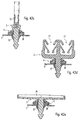
- Fig. 1 shows a connection 1 in a first embodiment between a carrier 2, in particular a body part a motor vehicle, and a not shown Plate element, in particular a door trim.
- This connection 1 has an upper part which can be fastened to the plate element 3 and a lower part 4 which can be connected to the carrier 2.
- the upper part 3 can be designed in any way. In the present Embodiment it has three flanges, the upper flange according to Fig. 2 spirally extending ribs can own.
- Die Locking elements 10 can, for example, circumferential rings, sawtooth-shaped thread areas or similar hook-like Be an entity.
- the intermediate region 5 is a in a carrier opening 7 storable engagement part 12 in the front Area penetrates and behind the carrier opening 7 spreads.
- the final state is here in a schematic section in Fig. 4 shown. 3 and 4 can also be seen that the engaging part 12 with at least one in the Latching elements 10 provided counter-latch 14 is.
- the engagement part shown in particular in FIGS. 3 and 4 in section 12 is advantageously a two-component part.
- it is made of a hard plastic material existing holding element 16 provided with the counter detent 14 and made of a softer plastic material Bearing element 18 formed.
- the holding element 16, as in a first embodiment in 5 and 6 is shown, for example, four diagonally have opposing webs 20 which in the bearing element 18 according to FIG. 4 are embedded.
- Crosspieces 20 can form a cross-shaped one above 5, which is on the inside is provided with the counter catches 14.
- This counter detents 14 As can be seen in particular from FIGS. 5 and 6, in the areas between two crossbars a, b, c and d.
- These crossbars can be in the form of thin webs be formed, and thus have a certain elasticity.
- the webs can according to Fig. 6 in the space between the cross beams protrude.
- This holding element 16 thus formed is shown in FIGS. 3 and 4 largely in the bearing element made of softer material 18 embedded.
- the intermediate area 5 for example is designed as a cylinder 22, which between at least two resilient guide wings 23 and one that acts on the inner wall 30 of the engagement part Cone 25 is located.
- 4 is in this context can be seen that the guide wing 23 the engaging part 12 tower above.
- These two resilient guide wings thus represent an assembly aid, for example according to 1 shows the connection according to the invention in a carrier opening 7 introduce. 8, the two guide wings 23 face each other diagonally. However, for example also several guide wings are used, which by Slots are separated. Preferably, these have Guide wing inclined ramps to facilitate insertion to facilitate in the beam opening.
- This plate element can be, for example, after Fig. 2 consisting of three disks upper part 3 over not Store pockets shown in more detail and thus ensure a safe Ensure connection to carrier 2 in the correct position.
- 9 and 10 show a further embodiment of the invention.
- 10 that the holding element 16 'provided with counter detents 14' is a circumferential, has inner recess 27.
- this recess 27 stores the bearing element 18 ', which for example from a ring 28 and an associated expansion element 29 exists.
- the expansion element 29 can be ring-shaped be formed and before final assembly on the carrier 2 in a groove 32 of the intermediate area 5 '.
- the expansion element in particular is constructive here designed a little differently and has a larger volume overall in a groove 32 of the intermediate area 5 '.
- the expansion element 29 has two surfaces 37 and 37a which are at an angle to one another on, which after pressing in the intermediate part 5 'in turn Spreading of the bearing element 18 '' 'takes place.
- the holding element has a profile area, which is embedded in the bearing element.
- This Profile area can for example be in the form of an undercut be designed, whereby the holding element, which with corresponding counter detents is provided on the bearing element holds.
- the holding element as at least partially in the bearing element embedded ring is formed, at least an area projecting beyond the bearing element at the same time Counter detent forms.
- the ring can be designed in this way, for example be that it consists of an outer, total embedded in the bearing part Ring area exists, which over webs with a inner ring area is connected to which several, each other opposing catches are.
- neck-shaped intermediate area there are various design options, such as instead of the two guide wings 23 according to FIG. 7 conical area may be present, which at its rear Provide several parallel webs at the end is.
- the upper part 3 has an intermediate area 5, which has longitudinal webs 48 and 49 on the outer circumference. These webs are preferably at the end with several Locking elements 10 'provided in FIG. 16.
- the webs 48 and 49 face each other diagonally, with the It is possible to provide a total of four webs.
- the Bridges can have different widths: for example have the webs 48 in the embodiment according to FIG. 16 a smaller width than the webs 49.
- the webs 49 go below the locking elements 10 'in a narrower version about. Are located between the webs 48 and 49 16 profiles 58.
- the upper part 3 is designed that the webs 48 and 49 have a tapered end Insertion area 47 are limited.
- An area I consists of a hard material and has a housing 44 with a recess 45 and counter detents 14 and an upper part of a Sealing flange 42. Connected integrally with this z. B. from a softer by a two-component injection molding process Material existing area II, which with a lower Part of the sealing flange 42 and with several through slots separate spreading elements 57 is provided.
- the housing 44 at least one longitudinal end connected to the recess 45 Has slot 55 or 55 '.
- the Slots 55 arranged on at least one surface of the housing, whereas the slots 55 'on at least one side wall of the housing 44.
- FIG. 19 shows the preassembled in a perspective view Unit of the connection, consisting of upper part 3 according to FIG. 16 and lower part 4 according to FIGS. 17 and 18.
- this Carrier 2 may be provided with a trough 66.
- the softer Material existing lower area of the sealing flange 42 in this context preferably has a circumferential one 17, which is the top of the trough 66 acted upon.
- FIGS. 23 to 34 show another embodiment of the invention.
- the upper part 3 according to FIGS. 23 and 24 again diagonally opposite webs 48 'and 49' with Latching elements 10 '.
- At this constriction 53 delimit two opposite one another according to FIGS. 23 and 24 resilient locking lugs 51, the base part 50 with each other diagonally opposite recesses 52 provided in FIG. 23 is.
- 25 to 28 shows this on the upper part 3 according to FIGS. 23 and 24 parked lower part 4.
- This in turn points above the Sealing flange 42 is a housing 44 with a recess 45 and with counter-catches arranged on the inside, preferably offset in height 14 according to FIGS. 27 and 28.
- Analogous to the above Embodiment is preferably the lower part 4 again Two-component part with an area I made of hard material and an area II made of softer material.
- the area II made of softer material forms the lower part of the sealing flange 42 and is in turn with a circumferential Provide sealing lip 38.
- the area I made of harder material has a lower zone on, which can extend through a carrier opening and especially in accordance with FIG. 27, notches 60 offset from one another owns.
- the unit consisting of upper part 3 and lower part 4 can be in preassembled form according to FIGS. 29, 30 and 31 into an opening 7 a carrier 2 can be used.
- the catches are 60 of the lower part 3 not yet spread and are stored in the Constriction 53 in the front part of the intermediate area 5. The result is a pre-assembled unit.
- 35 to 39 show another embodiment of the invention: here the lower part 4 in particular according to FIG. 37 to 39 above the sealing flange 42 several, each other opposite resilient webs 63, which on the inside are provided with the counter catches 14.
- the lower part 4 is again in the two-component spraying process made with an area I made of harder material, and an area II made of soft plastic material.
- Out Fig. 35 shows that area II is made of soft plastic material forms the lower region of the sealing flange 42 and is again provided with a sealing lip 38.
- the lower region of the lower part 4 is particularly shown in FIG. 38 and 39 with several, preferably diagonally opposite one another resilient spreading elements 57 'provided.
- the webs 63 in the longitudinal axis with respect to the expansion elements 57 'offset.
- the upper part 3 can, for example, in the embodiment according to Fig. 3 be designed and a cylindrical intermediate region 5, which is provided with the locking elements 10 is.
- the upper part 3 and the lower part 4 can initially as pre-assembled Unit delivered and inserted into the carrier opening 7 become. If pressure is now exerted on the upper part 3, the front part of the intermediate area 5 spreads the spreading elements 57 'of the lower part 4 and expands it according to FIG. 35 on. So that the connection according to the invention is flawless attached to a carrier 2.
- 40 and 41 illustrate another embodiment of the invention represents: here is the lower part 4 between two areas I. made of harder material with an area II made of softer material equipped, this area II the circumferential Has sealing lip 38.
- the area I has below the Carrier opening in turn expansion elements analogous to the aforementioned Embodiments. These expansion elements are by the inclined surfaces 61 of the front zone of the intermediate region 5 spread after insertion into an opening 7 of the carrier 2.
- the upper part 3 can be spaced apart from the three flanges lying apart from each other also two parallel at a distance have horizontal pipe holders 71 of known design.
- differently designed pipe holders can also be used 71 'are used which are designed in a manner known per se are.
- the upper part 3 can also be a have bowl-shaped longitudinal recess 74 to at least one Pipe not shown in more or less parallel to the surface to store the carrier 2 and, for example, no closer to hold illustrated cable straps.
Landscapes
- Engineering & Computer Science (AREA)
- General Engineering & Computer Science (AREA)
- Mechanical Engineering (AREA)
- Insertion Pins And Rivets (AREA)
- Vehicle Interior And Exterior Ornaments, Soundproofing, And Insulation (AREA)
- Connection Of Plates (AREA)
- Passenger Equipment (AREA)
- Vehicle Step Arrangements And Article Storage (AREA)
Applications Claiming Priority (2)
| Application Number | Priority Date | Filing Date | Title |
|---|---|---|---|
| DE19753678A DE19753678A1 (de) | 1997-12-03 | 1997-12-03 | Verbindung zwischen einem Träger, insbesondere einem Karosserieteil eines Kraftfahrzeuges, und einem Plattenelement, insbesondere einer Türverkleidung |
| DE19753678 | 1997-12-03 |
Publications (3)
| Publication Number | Publication Date |
|---|---|
| EP0921323A2 true EP0921323A2 (fr) | 1999-06-09 |
| EP0921323A3 EP0921323A3 (fr) | 1999-12-22 |
| EP0921323B1 EP0921323B1 (fr) | 2001-10-04 |
Family
ID=7850641
Family Applications (1)
| Application Number | Title | Priority Date | Filing Date |
|---|---|---|---|
| EP98110479A Expired - Lifetime EP0921323B1 (fr) | 1997-12-03 | 1998-06-08 | Joint entre un support, en particulier une pièce de carrosserie automobile, et un panneau, en particulier un panneau de garniture pour portes |
Country Status (4)
| Country | Link |
|---|---|
| US (1) | US6039523A (fr) |
| EP (1) | EP0921323B1 (fr) |
| DE (2) | DE19753678A1 (fr) |
| ES (1) | ES2163221T3 (fr) |
Cited By (17)
| Publication number | Priority date | Publication date | Assignee | Title |
|---|---|---|---|---|
| EP0964170A2 (fr) * | 1998-06-10 | 1999-12-15 | TRW Automotive Electronics & Components GmbH & Co. KG | Dispositif de fixation entre un support et un panneau, notamment d'une pièce de carrosserie d'un véhicule automobile |
| DE19921613A1 (de) * | 1999-05-10 | 2000-12-07 | Trw Carr France Ingwiller | Verbindungselement |
| DE19963721A1 (de) * | 1999-12-29 | 2001-07-12 | Raymond A & Cie | Kunststoffklammer zur lösbaren Verbindung einer Verkleidungsplatte mit einem Trägerteil |
| DE10064017A1 (de) * | 2000-10-10 | 2002-05-02 | Trw Automotive Electron & Comp | Vorrichtung zur Verbindung eines Trägers, insbesondere eines Karosserieteils eines Kraftfahrzeuges, mit einem Plattenelement, insbesondere einer Tür- oder Wandverkleidung |
| EP1571353A2 (fr) * | 2004-01-26 | 2005-09-07 | I.T.W. Espana, S.A. | Connecteur entre un panneau et un support |
| US7237995B2 (en) | 2004-01-26 | 2007-07-03 | Itw Espana, S.A. | Device for attaching a panel to a support |
| EP1958825A2 (fr) | 2007-02-13 | 2008-08-20 | TRW Automotive Electronics & Components GmbH | Dispositif de fixation |
| WO2011149952A1 (fr) | 2010-05-24 | 2011-12-01 | Burton Technologies, Llc | Fixation pour ensemble lampe de véhicule |
| EP2476921A1 (fr) * | 2011-01-13 | 2012-07-18 | Ateliers LR Etanco | Dispositif de fixation pour un revêtement isolant de bâtiment |
| EP2476922A1 (fr) * | 2011-01-13 | 2012-07-18 | Ateliers LR Etanco | Dispositif de fixation pour un revêtement isolant de bâtiment |
| FR3005123A1 (fr) * | 2013-04-30 | 2014-10-31 | Delahousse Et Fils Sa | Dispositif pour la fixation de deux pieces entre elles |
| WO2015160500A1 (fr) | 2014-04-16 | 2015-10-22 | Illinois Tool Works Inc. | Attache pour fixer un panneau sur un support, procédé de sa mise en œuvre, et équipement de véhicule à moteur |
| WO2016003578A1 (fr) | 2014-07-04 | 2016-01-07 | Illinois Tool Works Inc. | Dispositif de fixation pour panneaux |
| WO2016028369A1 (fr) * | 2014-08-18 | 2016-02-25 | Illinois Tool Works Inc. | Ensemble de fixation à broche et œillet |
| WO2017144570A1 (fr) * | 2016-02-26 | 2017-08-31 | Volkswagen Aktiengesellschaft | Connecteur de fixation, ensemble de pièces rapportées, dispositif de fixation |
| EP2855948B1 (fr) * | 2012-06-01 | 2018-01-03 | Gottlieb Binder Gmbh & Co. Kg | Système de fixation |
| US10315558B2 (en) | 2010-05-24 | 2019-06-11 | Burton Technologies, Llc | Locking position stud fastener for a vehicle lamp assembly |
Families Citing this family (60)
| Publication number | Priority date | Publication date | Assignee | Title |
|---|---|---|---|---|
| DE29718487U1 (de) * | 1997-10-17 | 1997-12-18 | Trw United-Carr Gmbh & Co Kg, 67677 Enkenbach-Alsenborn | Verbindung zwischen einem Träger, insbesondere einem Karosserieteil eines Kraftfahrzeugs, und einem Plattenelement |
| US6431023B1 (en) * | 1998-02-12 | 2002-08-13 | Ohi Seisakusho Co., Ltd. | Lever pivoting structure |
| DE19806827A1 (de) | 1998-02-18 | 1999-08-19 | Trw Automotive Electron & Comp | Verbindung zwischen einem Träger und einem Plattenelement |
| DE10000383B4 (de) * | 2000-01-07 | 2017-03-09 | Volkswagen Ag | Vorrichtung für die Anbringung einer Innenverkleidung an der Tür eines Kraftfahrzeuges |
| US6244805B1 (en) * | 2000-01-13 | 2001-06-12 | Illinois Tool Works Inc. | Sealed grommet |
| US7052221B2 (en) * | 2000-09-25 | 2006-05-30 | Pem Management, Inc. | Quick access rubber panel fastener |
| EP1323932B1 (fr) * | 2000-10-03 | 2005-04-27 | I.T.W. Espana, S.A. | Dispositif destine a l'assemblage d'un panneau sur une plaque de support |
| EP1324898B1 (fr) * | 2000-10-10 | 2004-12-08 | TRW Automotive Electronics & Components GmbH & Co. KG | Dispositif pour relier un support, notamment une partie de carrosserie d'une automobile, a un element en plaque, notamment a un revetement de porte ou de paroi |
| DE10053200C2 (de) * | 2000-10-26 | 2002-11-14 | Trw Automotive Electron & Comp | Verbindungselement |
| DE10055060A1 (de) * | 2000-11-07 | 2002-05-08 | Fischer Artur Werke Gmbh | Halter zum Befestigen eines Transponders an einer Schaltafel oder an einem Schalungszubehörteil |
| DE10116319C1 (de) * | 2001-04-02 | 2003-02-06 | Draexlmaier Lisa Gmbh | Befestigungsvorrichtung für ein Verkleidungsteil und Verfahren zur Befestigung eines Verkleidungsteils an einem Festteil |
| EP1389929B1 (fr) * | 2001-05-30 | 2008-09-03 | Pem Management, Inc. | Attache de panneaux a rotation rapide |
| US7004666B2 (en) * | 2001-10-09 | 2006-02-28 | Tyco Electronics Corporation | Quick-attach automotive antenna mounting assembly |
| US7134170B2 (en) * | 2001-11-21 | 2006-11-14 | Newfrey Llc | Plastic retaining clip for rib attachment |
| DE20120423U1 (de) | 2001-12-18 | 2002-05-02 | Rehau Ag + Co, 95111 Rehau | Elemente zur gleitfähigen Befestigung von Bauteilen |
| KR100444455B1 (ko) | 2001-12-24 | 2004-08-16 | 한국단자공업 주식회사 | 차량 도어용 커넥터 |
| WO2003064782A2 (fr) * | 2002-01-29 | 2003-08-07 | Newfrey Llc | Attache |
| US6874983B2 (en) * | 2002-04-11 | 2005-04-05 | Illinois Tool Works Inc. | Ergonomic fastener |
| JP2004116722A (ja) * | 2002-09-27 | 2004-04-15 | Nippon Pop Rivets & Fasteners Ltd | クリップ |
| US7033121B2 (en) * | 2002-09-30 | 2006-04-25 | Illinois Tool Works Inc | Water-tight grommet |
| US7114221B2 (en) * | 2003-01-17 | 2006-10-03 | Newfrey Llc | Two-piece interior trim retainer |
| JP4091859B2 (ja) * | 2003-03-03 | 2008-05-28 | 株式会社パイオラックス | 締結具 |
| DE20309399U1 (de) * | 2003-06-18 | 2003-08-28 | stryker Trauma GmbH, 24232 Schönkirchen | Knochennagel, insbesondere proximaler Femurnagel |
| DE10337027B4 (de) * | 2003-08-12 | 2009-05-07 | Daimler Ag | Verbindungs-Clip |
| WO2005051720A1 (fr) * | 2003-11-25 | 2005-06-09 | Harada Industry Co., Ltd. | Dispositif pour installer une antenne de toit pour vehicules |
| DE10358683B4 (de) * | 2003-12-12 | 2005-11-17 | A. Raymond & Cie | Vorrichtung zum Verbinden eines Trägerteils und eines Anbauteils |
| US20080007080A1 (en) * | 2003-12-18 | 2008-01-10 | Green Tokai Co., Ltd. | Clip With Dual Attachment Channels and Corresponding Clip House |
| JP2005188579A (ja) * | 2003-12-25 | 2005-07-14 | Nippon Pop Rivets & Fasteners Ltd | パネル等の固定具 |
| EP1577567B1 (fr) * | 2004-02-26 | 2006-03-08 | Faurecia Innenraum Systeme GmbH | Dispositif pour assembler deux éléments et structure utilisant cet dispositif |
| US7736107B2 (en) * | 2004-03-30 | 2010-06-15 | Piolax, Inc. | Clipping device |
| JP4649120B2 (ja) * | 2004-04-30 | 2011-03-09 | 株式会社パイオラックス | クリップ |
| JP4499614B2 (ja) * | 2004-05-31 | 2010-07-07 | 株式会社パイオラックス | クリップ |
| FR2872556B1 (fr) * | 2004-07-02 | 2006-11-17 | I T W De France Soc Par Action | Agrafe pour la fixation d'un panneau a un support munie d'une tete comportant un membre deformable |
| DE102004036621B4 (de) * | 2004-07-28 | 2007-04-26 | A. Raymond Et Cie | Spreizniet |
| CN2743973Y (zh) * | 2004-10-23 | 2005-11-30 | 鸿富锦精密工业(深圳)有限公司 | 散热器扣具 |
| US7267385B2 (en) * | 2005-08-18 | 2007-09-11 | Ford Global Technologies, Llc | Vehicle trim locating and attachment system |
| DE202005016824U1 (de) | 2005-10-26 | 2005-12-29 | Trw Automotive Electronics & Components Gmbh & Co. Kg | Verbindungselement |
| US7481474B2 (en) * | 2006-03-08 | 2009-01-27 | Newfrey Llc | Trim retainer |
| DE102007014984B4 (de) | 2006-04-20 | 2019-03-14 | Hbn-Teknik A/S | Befestigungselement mit dazugehörigem Stehbolzen |
| US7614836B2 (en) * | 2006-05-09 | 2009-11-10 | Gm Global Technology Operations, Inc. | Arrangements for attaching components to surfaces |
| US7793895B2 (en) * | 2006-06-13 | 2010-09-14 | Avery Dennison Corporation | Cable tie for an automotive valve cover |
| US20080052878A1 (en) * | 2006-08-31 | 2008-03-06 | Lewis Jeffrey C | Fastener Clip with Seal |
| DE102006049954B4 (de) * | 2006-10-19 | 2011-01-20 | Zimmer, Günther | Dübel für Deckplattenhinter- und eingriff |
| DE102006049952B4 (de) * | 2006-10-19 | 2011-02-10 | Zimmer, Günther | Dübel für Deckplattenhintergriff und Deckplatteneinspreizung |
| WO2008046410A1 (fr) * | 2006-10-19 | 2008-04-24 | Zimmer Guenther | Cheville à expansion pour insertion dans une plaque de recouvrement |
| DE202007002595U1 (de) * | 2007-02-22 | 2007-08-30 | Trw Automotive Electronics & Components Gmbh & Co. Kg | Befestigungsvorrichtung |
| US7927050B2 (en) * | 2007-05-30 | 2011-04-19 | Piolax Inc. | Interior part mounting clip |
| US7748089B2 (en) * | 2008-01-15 | 2010-07-06 | Illinois Tool Works Inc. | Auger clip assembly |
| US9610661B2 (en) * | 2010-05-24 | 2017-04-04 | Burton Technologies, Llc | Fastener for a vehicle lamp assembly |
| US8561265B2 (en) | 2011-04-12 | 2013-10-22 | Newfrey Llc | Interior trim fastener |
| US9878772B2 (en) * | 2012-01-10 | 2018-01-30 | Gulfstream Aerospace Corporation | Mounting assembly and method for mounting a sound-deadening body to a fuselage of an aircraft |
| DE102012016362B4 (de) * | 2012-08-17 | 2018-09-20 | Bayerische Motoren Werke Aktiengesellschaft | Befestigungsclip |
| FR3001007B1 (fr) * | 2013-01-14 | 2015-02-13 | Illinois Tool Works | Attache pour la fixation d'un panneau sur un support et ensemble a fixer sur ce support, pourvu d'une attache et d'un panneau |
| US10030682B2 (en) * | 2014-08-25 | 2018-07-24 | Ford Global Technologies, Llc | Two-part fastener |
| CN107645995B (zh) * | 2015-03-12 | 2021-04-09 | 伊利诺斯工具制品有限公司 | 可重复使用的紧固夹组件 |
| CN107939798B (zh) | 2016-10-12 | 2021-03-09 | 福特环球技术公司 | 用于车辆内饰的固定组件 |
| FR3062669B1 (fr) * | 2017-02-03 | 2020-10-02 | Renault Sas | Dispositif de fixation d'un panneau de porte sur une paroi laterale de caisse |
| DE102017128814A1 (de) * | 2017-12-05 | 2019-06-06 | Illinois Tool Works Inc. | Befestigungsvorrichtung |
| USD909183S1 (en) * | 2019-01-30 | 2021-02-02 | Otrajet Inc. | Buckle nail |
| CN112081807A (zh) * | 2019-06-14 | 2020-12-15 | 伊利诺斯工具制品有限公司 | 紧固件 |
Citations (2)
| Publication number | Priority date | Publication date | Assignee | Title |
|---|---|---|---|---|
| DE4014589C1 (fr) | 1990-05-07 | 1991-08-08 | Trw United-Carr Gmbh & Co Kg, 6753 Enkenbach-Alsenborn, De | |
| EP0726401A1 (fr) | 1995-02-13 | 1996-08-14 | TRW United-Carr GmbH & Co. KG | Liaison entre un support et un panneau |
Family Cites Families (6)
| Publication number | Priority date | Publication date | Assignee | Title |
|---|---|---|---|---|
| JPH0417859Y2 (fr) * | 1987-09-14 | 1992-04-21 | ||
| US4861208A (en) * | 1989-01-30 | 1989-08-29 | Chrysler Motors Corporation | Door trim panel fastening assembly |
| US5387065A (en) * | 1993-06-29 | 1995-02-07 | Illinios Tool Works Inc. | Reusable pin and grommet fastner |
| DE4330102C2 (de) * | 1993-09-06 | 1996-03-21 | United Carr Gmbh Trw | Verbindungselement |
| JP3251775B2 (ja) * | 1994-06-15 | 2002-01-28 | 株式会社ニフコ | クリップ |
| US5507610A (en) * | 1994-07-27 | 1996-04-16 | Emhart Inc. | Refusable fastener including a pin and grommet |
-
1997
- 1997-12-03 DE DE19753678A patent/DE19753678A1/de not_active Withdrawn
-
1998
- 1998-06-08 EP EP98110479A patent/EP0921323B1/fr not_active Expired - Lifetime
- 1998-06-08 ES ES98110479T patent/ES2163221T3/es not_active Expired - Lifetime
- 1998-06-08 DE DE59801625T patent/DE59801625D1/de not_active Expired - Lifetime
- 1998-12-02 US US09/204,997 patent/US6039523A/en not_active Expired - Fee Related
Patent Citations (2)
| Publication number | Priority date | Publication date | Assignee | Title |
|---|---|---|---|---|
| DE4014589C1 (fr) | 1990-05-07 | 1991-08-08 | Trw United-Carr Gmbh & Co Kg, 6753 Enkenbach-Alsenborn, De | |
| EP0726401A1 (fr) | 1995-02-13 | 1996-08-14 | TRW United-Carr GmbH & Co. KG | Liaison entre un support et un panneau |
Cited By (32)
| Publication number | Priority date | Publication date | Assignee | Title |
|---|---|---|---|---|
| EP0964170A2 (fr) * | 1998-06-10 | 1999-12-15 | TRW Automotive Electronics & Components GmbH & Co. KG | Dispositif de fixation entre un support et un panneau, notamment d'une pièce de carrosserie d'un véhicule automobile |
| EP0964170B1 (fr) * | 1998-06-10 | 2002-08-21 | TRW Automotive Electronics & Components GmbH & Co. KG | Dispositif de fixation entre un support et un panneau, notamment d'une pièce de carrosserie d'un véhicule automobile |
| DE19921613C2 (de) * | 1999-05-10 | 2003-10-02 | Trw Carr France Ingwiller | Verbindungselement |
| DE19921613A1 (de) * | 1999-05-10 | 2000-12-07 | Trw Carr France Ingwiller | Verbindungselement |
| DE19963721A1 (de) * | 1999-12-29 | 2001-07-12 | Raymond A & Cie | Kunststoffklammer zur lösbaren Verbindung einer Verkleidungsplatte mit einem Trägerteil |
| DE19963721B4 (de) * | 1999-12-29 | 2006-05-11 | A. Raymond & Cie | Kunststoffklammer zur lösbaren Verbindung einer Verkleidungsplatte mit einem Trägerteil |
| DE10064017A1 (de) * | 2000-10-10 | 2002-05-02 | Trw Automotive Electron & Comp | Vorrichtung zur Verbindung eines Trägers, insbesondere eines Karosserieteils eines Kraftfahrzeuges, mit einem Plattenelement, insbesondere einer Tür- oder Wandverkleidung |
| DE10064017C2 (de) * | 2000-10-10 | 2003-06-26 | Trw Automotive Electron & Comp | Vorrichtung zur Verbindung eines Trägers, insbesondere eines Karosserieteils eines Kraftfahrzeuges, mit einem Plattenelement, insbesondere einer Tür- oder Wandverkleidung |
| EP1571353A2 (fr) * | 2004-01-26 | 2005-09-07 | I.T.W. Espana, S.A. | Connecteur entre un panneau et un support |
| EP1571353A3 (fr) * | 2004-01-26 | 2006-12-27 | I.T.W. Espana, S.A. | Connecteur entre un panneau et un support |
| US7213378B2 (en) | 2004-01-26 | 2007-05-08 | Itw Espana, S.A. | Connection part between a panel and a support |
| US7237995B2 (en) | 2004-01-26 | 2007-07-03 | Itw Espana, S.A. | Device for attaching a panel to a support |
| EP1958825A2 (fr) | 2007-02-13 | 2008-08-20 | TRW Automotive Electronics & Components GmbH | Dispositif de fixation |
| EP1958825A3 (fr) * | 2007-02-13 | 2009-11-04 | TRW Automotive Electronics & Components GmbH | Dispositif de fixation |
| US7862275B2 (en) | 2007-02-13 | 2011-01-04 | Trw Automotive Electronics & Components Gmbh | Fastening device |
| EP2577073A4 (fr) * | 2010-05-24 | 2016-10-12 | Burton Technologies Llc | Fixation pour ensemble lampe de véhicule |
| WO2011149952A1 (fr) | 2010-05-24 | 2011-12-01 | Burton Technologies, Llc | Fixation pour ensemble lampe de véhicule |
| US10315558B2 (en) | 2010-05-24 | 2019-06-11 | Burton Technologies, Llc | Locking position stud fastener for a vehicle lamp assembly |
| EP2476922A1 (fr) * | 2011-01-13 | 2012-07-18 | Ateliers LR Etanco | Dispositif de fixation pour un revêtement isolant de bâtiment |
| FR2970493A1 (fr) * | 2011-01-13 | 2012-07-20 | Lr Etanco Atel | Dispositif de fixation pour un revetement isolant de batiment. |
| EP2476921A1 (fr) * | 2011-01-13 | 2012-07-18 | Ateliers LR Etanco | Dispositif de fixation pour un revêtement isolant de bâtiment |
| US10144366B2 (en) | 2012-06-01 | 2018-12-04 | Gottlieb Binder Gmbh & Co. Kg | Fastening system |
| EP2855948B1 (fr) * | 2012-06-01 | 2018-01-03 | Gottlieb Binder Gmbh & Co. Kg | Système de fixation |
| FR3005123A1 (fr) * | 2013-04-30 | 2014-10-31 | Delahousse Et Fils Sa | Dispositif pour la fixation de deux pieces entre elles |
| WO2015160500A1 (fr) | 2014-04-16 | 2015-10-22 | Illinois Tool Works Inc. | Attache pour fixer un panneau sur un support, procédé de sa mise en œuvre, et équipement de véhicule à moteur |
| US10124744B2 (en) | 2014-04-16 | 2018-11-13 | Illinois Tool Works Inc. | Clip for fastening a panel on a support, method for implementing same, and motor vehicle equipment |
| FR3020099A1 (fr) * | 2014-04-16 | 2015-10-23 | Illinois Tool Works | Agrafe de fixation d'un panneau sur un support, procede de mise en oeuvre et equipement automobile |
| CN106471264A (zh) * | 2014-07-04 | 2017-03-01 | 伊利诺斯工具制品有限公司 | 面板的紧固装置 |
| WO2016003578A1 (fr) | 2014-07-04 | 2016-01-07 | Illinois Tool Works Inc. | Dispositif de fixation pour panneaux |
| WO2016028369A1 (fr) * | 2014-08-18 | 2016-02-25 | Illinois Tool Works Inc. | Ensemble de fixation à broche et œillet |
| US10221873B2 (en) | 2014-08-18 | 2019-03-05 | Illinois Tool Works Inc. | Pin and grommet fastener assembly |
| WO2017144570A1 (fr) * | 2016-02-26 | 2017-08-31 | Volkswagen Aktiengesellschaft | Connecteur de fixation, ensemble de pièces rapportées, dispositif de fixation |
Also Published As
| Publication number | Publication date |
|---|---|
| DE19753678A1 (de) | 1999-06-10 |
| DE59801625D1 (de) | 2001-11-08 |
| ES2163221T3 (es) | 2002-01-16 |
| EP0921323B1 (fr) | 2001-10-04 |
| EP0921323A3 (fr) | 1999-12-22 |
| US6039523A (en) | 2000-03-21 |
Similar Documents
| Publication | Publication Date | Title |
|---|---|---|
| EP0921323B1 (fr) | Joint entre un support, en particulier une pièce de carrosserie automobile, et un panneau, en particulier un panneau de garniture pour portes | |
| DE10064017C2 (de) | Vorrichtung zur Verbindung eines Trägers, insbesondere eines Karosserieteils eines Kraftfahrzeuges, mit einem Plattenelement, insbesondere einer Tür- oder Wandverkleidung | |
| DE69706714T2 (de) | An einer Wand befestigbare Schraubbolzen-Muttereinheit | |
| EP1025368B1 (fr) | Element d'assemblage entre un support, notamment un element de carrosserie d'un vehicule a moteur, et un panneau | |
| DE2702643B2 (de) | Beschlag zum lösbaren Verbinden zweier senkrecht aufeinanderstoßender Bauteile, insbesondere Möbelteile | |
| DE202007002071U1 (de) | Befestigungsvorrichtung | |
| EP0726401A1 (fr) | Liaison entre un support et un panneau | |
| EP0735283A2 (fr) | Dispositif de fixation | |
| EP1177387B1 (fr) | Element d'assemblage | |
| EP0861380B1 (fr) | Ecrou en matiere plastique pour l'assemblage d'elements du type plaque | |
| EP1013978B1 (fr) | Dispositif de fixation en matière plastique | |
| DE3715496C2 (fr) | ||
| EP0730998B1 (fr) | Baguette de recouvrement d'une gouttière de toit de véhicule | |
| DE60314807T2 (de) | Dichtungsvorrichtung | |
| DE3514765C2 (fr) | ||
| DE2929461C2 (de) | Haltedübel | |
| EP1324898A1 (fr) | Dispositif pour relier un support, notamment une partie de carrosserie d'une automobile, a un element en plaque, notamment a un revetement de porte ou de paroi | |
| DE19600931A1 (de) | Dübel | |
| DE2236766A1 (de) | Befestigungsclip | |
| EP0667463B1 (fr) | Elément de support en matière plastique, en particulier pour tuyaux | |
| DE4427723A1 (de) | Zweiteiliges Befestigungssystem | |
| DE19640581A1 (de) | Spreizdübel | |
| DE102018107083A1 (de) | Befestigungseinrichtung und Verfahren zur Befestigung eines Anbauteils an einem Tragteil, Bauteilsystem und Kraftfahrzeug | |
| DE1965109A1 (de) | Metall-Federklammer | |
| DE19522791C1 (de) | Verbundprofil und Verfahren zu seiner Herstellung |
Legal Events
| Date | Code | Title | Description |
|---|---|---|---|
| PUAI | Public reference made under article 153(3) epc to a published international application that has entered the european phase |
Free format text: ORIGINAL CODE: 0009012 |
|
| AK | Designated contracting states |
Kind code of ref document: A2 Designated state(s): DE ES FR GB |
|
| AX | Request for extension of the european patent |
Free format text: AL;LT;LV;MK;RO;SI |
|
| PUAL | Search report despatched |
Free format text: ORIGINAL CODE: 0009013 |
|
| AK | Designated contracting states |
Kind code of ref document: A3 Designated state(s): AT BE CH CY DE DK ES FI FR GB GR IE IT LI LU MC NL PT SE |
|
| AX | Request for extension of the european patent |
Free format text: AL;LT;LV;MK;RO;SI |
|
| 17P | Request for examination filed |
Effective date: 20000128 |
|
| AKX | Designation fees paid |
Free format text: DE ES FR GB |
|
| GRAG | Despatch of communication of intention to grant |
Free format text: ORIGINAL CODE: EPIDOS AGRA |
|
| GRAG | Despatch of communication of intention to grant |
Free format text: ORIGINAL CODE: EPIDOS AGRA |
|
| GRAH | Despatch of communication of intention to grant a patent |
Free format text: ORIGINAL CODE: EPIDOS IGRA |
|
| 17Q | First examination report despatched |
Effective date: 20010223 |
|
| GRAH | Despatch of communication of intention to grant a patent |
Free format text: ORIGINAL CODE: EPIDOS IGRA |
|
| GRAA | (expected) grant |
Free format text: ORIGINAL CODE: 0009210 |
|
| AK | Designated contracting states |
Kind code of ref document: B1 Designated state(s): DE ES FR GB |
|
| REF | Corresponds to: |
Ref document number: 59801625 Country of ref document: DE Date of ref document: 20011108 |
|
| REG | Reference to a national code |
Ref country code: GB Ref legal event code: IF02 |
|
| GBT | Gb: translation of ep patent filed (gb section 77(6)(a)/1977) |
Effective date: 20011218 |
|
| REG | Reference to a national code |
Ref country code: ES Ref legal event code: FG2A Ref document number: 2163221 Country of ref document: ES Kind code of ref document: T3 |
|
| ET | Fr: translation filed | ||
| PLBE | No opposition filed within time limit |
Free format text: ORIGINAL CODE: 0009261 |
|
| STAA | Information on the status of an ep patent application or granted ep patent |
Free format text: STATUS: NO OPPOSITION FILED WITHIN TIME LIMIT |
|
| 26N | No opposition filed | ||
| PGFP | Annual fee paid to national office [announced via postgrant information from national office to epo] |
Ref country code: FR Payment date: 20100630 Year of fee payment: 13 Ref country code: ES Payment date: 20100628 Year of fee payment: 13 |
|
| PGFP | Annual fee paid to national office [announced via postgrant information from national office to epo] |
Ref country code: GB Payment date: 20100625 Year of fee payment: 13 Ref country code: DE Payment date: 20100629 Year of fee payment: 13 |
|
| GBPC | Gb: european patent ceased through non-payment of renewal fee |
Effective date: 20110608 |
|
| REG | Reference to a national code |
Ref country code: FR Ref legal event code: ST Effective date: 20120229 |
|
| REG | Reference to a national code |
Ref country code: DE Ref legal event code: R119 Ref document number: 59801625 Country of ref document: DE Effective date: 20120103 |
|
| PG25 | Lapsed in a contracting state [announced via postgrant information from national office to epo] |
Ref country code: DE Free format text: LAPSE BECAUSE OF NON-PAYMENT OF DUE FEES Effective date: 20120103 Ref country code: FR Free format text: LAPSE BECAUSE OF NON-PAYMENT OF DUE FEES Effective date: 20110630 |
|
| PG25 | Lapsed in a contracting state [announced via postgrant information from national office to epo] |
Ref country code: GB Free format text: LAPSE BECAUSE OF NON-PAYMENT OF DUE FEES Effective date: 20110608 |
|
| REG | Reference to a national code |
Ref country code: ES Ref legal event code: FD2A Effective date: 20121116 |
|
| PG25 | Lapsed in a contracting state [announced via postgrant information from national office to epo] |
Ref country code: ES Free format text: LAPSE BECAUSE OF NON-PAYMENT OF DUE FEES Effective date: 20110609 |