EP1324898B1 - Dispositif pour relier un support, notamment une partie de carrosserie d'une automobile, a un element en plaque, notamment a un revetement de porte ou de paroi - Google Patents
Dispositif pour relier un support, notamment une partie de carrosserie d'une automobile, a un element en plaque, notamment a un revetement de porte ou de paroi Download PDFInfo
- Publication number
- EP1324898B1 EP1324898B1 EP01986649A EP01986649A EP1324898B1 EP 1324898 B1 EP1324898 B1 EP 1324898B1 EP 01986649 A EP01986649 A EP 01986649A EP 01986649 A EP01986649 A EP 01986649A EP 1324898 B1 EP1324898 B1 EP 1324898B1
- Authority
- EP
- European Patent Office
- Prior art keywords
- region
- connecting element
- elements
- final assembly
- latching elements
- Prior art date
- Legal status (The legal status is an assumption and is not a legal conclusion. Google has not performed a legal analysis and makes no representation as to the accuracy of the status listed.)
- Expired - Lifetime
Links
- 238000007789 sealing Methods 0.000 claims description 10
- 230000013011 mating Effects 0.000 claims 2
- 238000003780 insertion Methods 0.000 description 4
- 230000037431 insertion Effects 0.000 description 4
- 230000002093 peripheral effect Effects 0.000 description 3
- 238000010276 construction Methods 0.000 description 2
- 239000012876 carrier material Substances 0.000 description 1
- 238000011161 development Methods 0.000 description 1
- 230000018109 developmental process Effects 0.000 description 1
Images


Classifications
-
- F—MECHANICAL ENGINEERING; LIGHTING; HEATING; WEAPONS; BLASTING
- F16—ENGINEERING ELEMENTS AND UNITS; GENERAL MEASURES FOR PRODUCING AND MAINTAINING EFFECTIVE FUNCTIONING OF MACHINES OR INSTALLATIONS; THERMAL INSULATION IN GENERAL
- F16B—DEVICES FOR FASTENING OR SECURING CONSTRUCTIONAL ELEMENTS OR MACHINE PARTS TOGETHER, e.g. NAILS, BOLTS, CIRCLIPS, CLAMPS, CLIPS OR WEDGES; JOINTS OR JOINTING
- F16B5/00—Joining sheets or plates, e.g. panels, to one another or to strips or bars parallel to them
- F16B5/12—Fastening strips or bars to sheets or plates, e.g. rubber strips, decorative strips for motor vehicles, by means of clips
- F16B5/123—Auxiliary fasteners specially designed for this purpose
-
- B—PERFORMING OPERATIONS; TRANSPORTING
- B60—VEHICLES IN GENERAL
- B60R—VEHICLES, VEHICLE FITTINGS, OR VEHICLE PARTS, NOT OTHERWISE PROVIDED FOR
- B60R13/00—Elements for body-finishing, identifying, or decorating; Arrangements or adaptations for advertising purposes
- B60R13/04—External Ornamental or guard strips; Ornamental inscriptive devices thereon
-
- F—MECHANICAL ENGINEERING; LIGHTING; HEATING; WEAPONS; BLASTING
- F16—ENGINEERING ELEMENTS AND UNITS; GENERAL MEASURES FOR PRODUCING AND MAINTAINING EFFECTIVE FUNCTIONING OF MACHINES OR INSTALLATIONS; THERMAL INSULATION IN GENERAL
- F16B—DEVICES FOR FASTENING OR SECURING CONSTRUCTIONAL ELEMENTS OR MACHINE PARTS TOGETHER, e.g. NAILS, BOLTS, CIRCLIPS, CLAMPS, CLIPS OR WEDGES; JOINTS OR JOINTING
- F16B19/00—Bolts without screw-thread; Pins, including deformable elements; Rivets
- F16B19/008—Bolts without screw-thread; Pins, including deformable elements; Rivets with sealing means
-
- F—MECHANICAL ENGINEERING; LIGHTING; HEATING; WEAPONS; BLASTING
- F16—ENGINEERING ELEMENTS AND UNITS; GENERAL MEASURES FOR PRODUCING AND MAINTAINING EFFECTIVE FUNCTIONING OF MACHINES OR INSTALLATIONS; THERMAL INSULATION IN GENERAL
- F16B—DEVICES FOR FASTENING OR SECURING CONSTRUCTIONAL ELEMENTS OR MACHINE PARTS TOGETHER, e.g. NAILS, BOLTS, CIRCLIPS, CLAMPS, CLIPS OR WEDGES; JOINTS OR JOINTING
- F16B5/00—Joining sheets or plates, e.g. panels, to one another or to strips or bars parallel to them
- F16B5/06—Joining sheets or plates, e.g. panels, to one another or to strips or bars parallel to them by means of clamps or clips
- F16B5/0607—Joining sheets or plates, e.g. panels, to one another or to strips or bars parallel to them by means of clamps or clips joining sheets or plates to each other
- F16B5/0621—Joining sheets or plates, e.g. panels, to one another or to strips or bars parallel to them by means of clamps or clips joining sheets or plates to each other in parallel relationship
- F16B5/0628—Joining sheets or plates, e.g. panels, to one another or to strips or bars parallel to them by means of clamps or clips joining sheets or plates to each other in parallel relationship allowing for adjustment parallel or perpendicular to the plane of the sheets or plates
Definitions
- the invention relates to a device for connecting a carrier, in particular a body part of a motor vehicle, with a plate element, in particular a door or wall paneling, with a connecting element on the Plate element attachable top and a connectable to the carrier base, wherein between the upper part and the lower part with a latching elements provided, neck-shaped formed intermediate region is provided which a in a carrier opening einlagerbares engagement part interspersed, according to the preamble of claim 1, (according to US-A-6 039 523).
- the object of present invention a device for connecting a carrier with a To provide plate element, in which a precise vote of inputs and Pull-off forces during assembly or disassembly is present; So it should be a fine-tuning be ensured in the assembly with the least possible scattering of forces.
- the device according to the invention has a high efficiency.
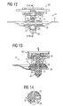
- the device according to the invention for connecting a device shown in FIG. 12 illustrated carrier 2, in particular a body part of a motor vehicle, with a plate element, not shown, in particular a door or Wall covering revealed.
- the device is made of plastic.
- the device according to the invention essentially consists of a connecting element 1 according to FIG. 7, an intermediate part 15 according to FIG. 8, a sealing element 20 according to FIG Fig. 9, an engaging member 12 of FIG. 10 and a cap 50 of FIG. 11.
- the connecting part 1 has two spaced apart flanges 70 and 71, which with a e.g. in Figs. 5 and 6 locking member 62 shown together act, i. are insertable in this.
- an intermediate region 5 of the connecting element 1 has a first Region I and a second region II of the latching elements 10, wherein the first Region I and the second region II separated by an intermediate neck 28 are.
- the two aforementioned areas are each as a circumferential groove 32 and 34th educated.
- the preassembled unit V is equipped according to FIG. 1 to 4 with a locking part 62, which is shown in more detail in FIGS. 5 and 6.
- This locking member 62 has a slot 65, which for receiving the upper flange 70 of the locking part 1 serves.
- the lower flange 71 bears on the underside of the locking part 62 on.
- the locking member 62 has a plurality of spirally extending, on known retaining ribs 67.
- Fig. 7 the connecting element 1 in side view, in plan view and in the middle section shown in more detail.
- first region I i. the groove 32 of Locking elements 10
- second area II i. the groove 34 through an intermediate neck 28 separated from each other.
- slopes 57 connect, which in storage areas 55 pass over.
- webs 24 In the area of these storage areas are webs 24; in the area above the groove 34 webs 30 are provided.
- the lower part 4 of the connecting element 1, which limits the storage areas 55, is equipped with a catch 52.
- This Intermediate part 15 is disc-shaped with a central region with the counter-locking elements 22 and the arranged between slots 31 Fig. 8 b in the area a passage opening 36 for the intermediate region 5 of the connecting element. 1 Furthermore, a peripheral region with diagonally opposite recesses Provided 38, which serve as latches for the locking lugs 18. Between the recesses 38 of the intermediate part 15 are engaging portions 33rd for storing at least one tongue 41 of the sealing element shown in more detail in FIG. 9.
- the first region I i. the groove 32 of the locking element. 1 locked with the counter-locking elements 22 of the intermediate part 15.
- the counter-latching elements 22 of the intermediate part 15 engage in the second area II, i. in the circumferential groove 34 of the locking elements 10 of the connecting part 1.
- the aforementioned sealing element 20 is shown in more detail. It is e.g. formed as a rubber disc with at least one tongue 41 and four diagonally opposite passage openings 21 and a middle Opening 27.
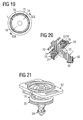
- FIG. 10 shows the engagement part 12 in a side view, in plan view and in section c-c.
- This engagement part 12 has z. B. four diagonally opposite webs 18th in which, in particular according to FIG. 20, the recesses 38 of the intermediate part 15 grab behind and are locked behind this.
- Fig. 11 shows the cap 50 in side view, in plan view and in section c-c.
- Cap 50 has a through hole 51 and can be particularly according to the Fig. 1, 2, 4, 12, 17 and 20 with the lower part 4 of the connecting element 1 lock.
- the peripheral areas of the cap 50 in this case enclose according to the aforementioned FIG. in the preassembled position F, the lower, outer regions of the spreading 25th of the engagement part 12. After the final assembly E are these aforementioned areas In particular, as shown in FIG. 17 removed from the peripheral surface of the cap 50.
- the sealing element 20 acts in this position, the top of the carrier 2 and thus properly seals the carrier opening 7.
- the entire unit is functionally reliable locked together, regardless of the thickness of the carrier. 2
- the entire device is simple in construction and has a high degree of effectiveness, in particular, a repeated assembly or disassembly is possible without the individual parts must be destroyed.
- the aforementioned forces are independent of the thickness of the carrier material.
Landscapes
- Engineering & Computer Science (AREA)
- General Engineering & Computer Science (AREA)
- Mechanical Engineering (AREA)
- Connection Of Plates (AREA)
- Vehicle Interior And Exterior Ornaments, Soundproofing, And Insulation (AREA)
- Clamps And Clips (AREA)
- Insertion Pins And Rivets (AREA)
Claims (11)
- Dispositif pour relier un support (2), en particulier une partie de carrosserie de véhicule automobile à un élément en plaque, en particulier un habillage d'une porte ou d'une paroi,
doté d'un élément de liaison (1) comprenant une partie supérieure (3) destinée à être fixer à l'élément en plaque et une partie inférieure (4) destinée à être fixée au support (2),
dans lequel entre la partie supérieure (3) et la partie inférieure (4) une partie intermédiaire (5), conçue en forme de gorge et dotée d'éléments d'encliquetage (10) est prévue, laquelle partie intermédiaire traverse une pièce d'accrochage (12) pouvant être insérée dans une ouverture (7) du support,
dans lequel la partie intermédiaire (5) au dessus du support (2) est entourée d'une pièce intermédiaire (15) pouvant se verrouiller avec les éléments d'encliquetage (10) et
dans lequel la partie intermédiaire (5) de l'élément de liaison (1) présente une première zone (I) et une deuxième zone (II) des éléments d'encliquetage (10), la première zone (I) dans le prémontage et la deuxième zone (II) dans le montage final des éléments d'encliquetage (10) étant verrouillée avec des éléments d'encliquetage conjugués (22) de la pièce intermédiaire (15), et
dans le montage final (E), au travers de la zone d'extrémité (4) de l'élément de liaison (1), des éléments d'écartements (25) de la pièce d'accrochage (12) s'écartent simultanément dans la zone de l'ouverture du support (7),
dans lequel la première et la seconde zone (I, II) des éléments d'encliquetage (10) sont formées chacune d'une rainure circulaire (32, 34) et
la première et la seconde zone (I, II) des éléments d'encliquetage (10) sont séparées l'une de l'autre par une gorge intermédiaire (28),
caractérisé en ce que,
entre la pièce intermédiaire (15) et la pièce d'accrochage (12) est disposé un élément d'étanchéité (20), coiffant la face supérieure du support (2), et
en ce que l'élément de liaison (1) présente au moins deux nervures (30) disposées en diagonales l'une par rapport à l'autre, qui lors du montage final (E) sont logées dans des fentes (31) de la pièce intermédiaire (15). - Dispositif selon la revendication 1, caractérisé en ce que la pièce intermédiaire (15) est conçue en forme de disque avec, dans une zone centrale, les éléments d'encliquetage conjugués (22), entres lesquels sont positionnées les fentes (31) au niveau d'une ouverture de passage (36) pour la partie intermédiaire (5) de l'élément de liaison (1) et avec une partie périphérique comprenant des creux (38) disposés en diagonale les uns par rapport aux autres (fig. 8a-8c).
- Elément de liaison selon la revendication 1, caractérisé en ce qu' un capuchon (50) est fixé à l'extrémité de la partie inférieure (4) de l'élément de liaison (1).
- Dispositif selon la revendication 3, caractérisé en ce que le capuchon (50) est encliqueté dans une encoche (52) de la partie inférieure (4).
- Dispositif selon la revendication 4, caractérisé en ce que la partie inférieure (4) de l'élément de liaison (1) présente, derrière l'encoche (52), des logements (55) pour les éléments d'écartement (25) de la pièce d'accrochage (12) en position de prémontage (V) (fig.13).
- Dispositif selon la revendication 5, caractérisé en ce que les logements (55) de la partie inférieure (4) de l'élément de liaison (1) sont séparés les uns des autres par des nervures (24).
- Dispositif selon la revendication 6, caractérisé en ce qu'aux logements (55) de la partie inférieure (4) succèdent des pentes coniques susceptibles d'écarter les éléments d'écartement (25) de la pièce d'accrochage (12) lors du déplacement de l'élément de liaison (1) de la position de prémontage (V) dans la position de montage final (E) (fig.17).
- Dispositif selon la revendication 7, caractérisé en ce que, dans le montage final (E), les éléments d'écartement (25) écartés portent sur des surfaces planes (59) de la partie inférieure (4) de l'élément de liaison (1).
- Dispositif selon l'une ou plusieurs des revendications précédentes caractérisé en ce que la pièce d'accrochage (12) présente, au dessus des éléments d'écartement (25) des saillies (18) pouvant se loger dans les creux (38) de la pièce intermédiaire (15).
- Dispositif selon la revendication 9, caractérisé en ce que, entre les creux (38) de la pièce intermédiaire (15), se trouvent des zones d'accrochage (33) pour loger au moins un ergot (41) de la pièce d'étanchéité (20) lors du prémontage (V) et du montage final (E).
- Dispositif selon la revendication 9 et 10, caractérisé en ce que la pièce d'étanchéité (20) présente des ouvertures de passage (21) pour les saillies (18) de la pièce d'accrochage (12).
Applications Claiming Priority (5)
| Application Number | Priority Date | Filing Date | Title |
|---|---|---|---|
| DE20017376U DE20017376U1 (de) | 2000-10-10 | 2000-10-10 | Vorrichtung zur Verbindung eines Trägers, insbesondere eines Karosserieteils eines Kraftfahrzeuges, mit einem Plattenelement, insbesondere einer Tür- oder Wandverkleidung |
| DE20017376U | 2000-10-10 | ||
| DE10064017 | 2000-12-21 | ||
| DE10064017A DE10064017C2 (de) | 2000-10-10 | 2000-12-21 | Vorrichtung zur Verbindung eines Trägers, insbesondere eines Karosserieteils eines Kraftfahrzeuges, mit einem Plattenelement, insbesondere einer Tür- oder Wandverkleidung |
| PCT/DE2001/003829 WO2002030710A1 (fr) | 2000-10-10 | 2001-10-09 | Dispositif pour relier un support, notamment une partie de carrosserie d'une automobile, a un element en plaque, notamment a un revetement de porte ou de paroi |
Publications (2)
| Publication Number | Publication Date |
|---|---|
| EP1324898A1 EP1324898A1 (fr) | 2003-07-09 |
| EP1324898B1 true EP1324898B1 (fr) | 2004-12-08 |
Family
ID=26008025
Family Applications (1)
| Application Number | Title | Priority Date | Filing Date |
|---|---|---|---|
| EP01986649A Expired - Lifetime EP1324898B1 (fr) | 2000-10-10 | 2001-10-09 | Dispositif pour relier un support, notamment une partie de carrosserie d'une automobile, a un element en plaque, notamment a un revetement de porte ou de paroi |
Country Status (4)
| Country | Link |
|---|---|
| EP (1) | EP1324898B1 (fr) |
| JP (1) | JP3787327B2 (fr) |
| ES (1) | ES2233707T3 (fr) |
| WO (1) | WO2002030710A1 (fr) |
Families Citing this family (6)
| Publication number | Priority date | Publication date | Assignee | Title |
|---|---|---|---|---|
| DE10358683B4 (de) * | 2003-12-12 | 2005-11-17 | A. Raymond & Cie | Vorrichtung zum Verbinden eines Trägerteils und eines Anbauteils |
| ES2246681B1 (es) * | 2004-01-26 | 2007-03-16 | I.T.W. España, S.A. | Dispositivo de fijacion entre un panel y un soporte. |
| DE202008006958U1 (de) | 2008-05-23 | 2008-10-02 | Trw Automotive Electronics & Components Gmbh | Verbindungsbaugruppe zur Befestigung eines Anbauelements auf einem Träger |
| ES2555666B1 (es) | 2014-07-04 | 2016-10-14 | Illinois Tool Works Inc. | Dispositivo de fijación en paneles |
| US10221873B2 (en) | 2014-08-18 | 2019-03-05 | Illinois Tool Works Inc. | Pin and grommet fastener assembly |
| EP3839272B1 (fr) * | 2019-12-18 | 2023-08-23 | Illinois Tool Works INC. | Fixation et ensemble la comprenant |
Family Cites Families (4)
| Publication number | Priority date | Publication date | Assignee | Title |
|---|---|---|---|---|
| US4568215A (en) * | 1983-11-21 | 1986-02-04 | Illinois Tool Works Inc. | Laterally adjustable fastening assembly |
| US5236272A (en) * | 1991-05-31 | 1993-08-17 | Eastman Kodak Company | Mounting apparatus for rotatable optical disk |
| JP3450342B2 (ja) * | 1991-12-16 | 2003-09-22 | 株式会社ニフコ | 止め具 |
| DE19753678A1 (de) * | 1997-12-03 | 1999-06-10 | United Carr Gmbh Trw | Verbindung zwischen einem Träger, insbesondere einem Karosserieteil eines Kraftfahrzeuges, und einem Plattenelement, insbesondere einer Türverkleidung |
-
2001
- 2001-10-09 ES ES01986649T patent/ES2233707T3/es not_active Expired - Lifetime
- 2001-10-09 WO PCT/DE2001/003829 patent/WO2002030710A1/fr active IP Right Grant
- 2001-10-09 JP JP2002534112A patent/JP3787327B2/ja not_active Expired - Fee Related
- 2001-10-09 EP EP01986649A patent/EP1324898B1/fr not_active Expired - Lifetime
Also Published As
| Publication number | Publication date |
|---|---|
| ES2233707T3 (es) | 2005-06-16 |
| WO2002030710A1 (fr) | 2002-04-18 |
| EP1324898A1 (fr) | 2003-07-09 |
| JP2004510937A (ja) | 2004-04-08 |
| JP3787327B2 (ja) | 2006-06-21 |
Similar Documents
| Publication | Publication Date | Title |
|---|---|---|
| DE10064017C2 (de) | Vorrichtung zur Verbindung eines Trägers, insbesondere eines Karosserieteils eines Kraftfahrzeuges, mit einem Plattenelement, insbesondere einer Tür- oder Wandverkleidung | |
| EP0954459B1 (fr) | Element de fixation | |
| DE4330102C2 (de) | Verbindungselement | |
| DE19930728B4 (de) | Dübel zum Befestigen eines Gegenstandes an einem Träger aus Flachmaterial | |
| EP1958825A2 (fr) | Dispositif de fixation | |
| DE102017117002A1 (de) | Vorrichtung zum Befestigen eines Bauteils an einem Trägerbauteil | |
| WO2005060331A2 (fr) | Dispositif pour assembler une piece de support et une piece a rapporter | |
| EP0921323A2 (fr) | Joint entre un support, en particulier une pièce de carrosserie automobile, et un panneau, en particulier un panneau de garniture pour portes | |
| EP1717453A1 (fr) | Clip et système de fixation avec un clip | |
| CH677379A5 (fr) | ||
| DE102005015033A1 (de) | Befestigungselement zur Anbringung auf einem Gewindebolzen | |
| DE102010024870A1 (de) | Vorrichtung zum Befestigen eines Bauteils an einem Befestigungsbolzen | |
| DE202007011105U1 (de) | Einteiliger Clip aus Kunststoff | |
| WO2010034486A1 (fr) | Dispositif de fixation | |
| DE102019126620A1 (de) | Befestigungsvorrichtung | |
| DE19921613A1 (de) | Verbindungselement | |
| EP1324898B1 (fr) | Dispositif pour relier un support, notamment une partie de carrosserie d'une automobile, a un element en plaque, notamment a un revetement de porte ou de paroi | |
| DE3715496C2 (fr) | ||
| DE202005019612U1 (de) | Vorrichtung zur lösbaren Befestigung eines flachen Bauteils an einer Trägerstruktur | |
| EP2304250B1 (fr) | Clip à vis | |
| DE102017011237A1 (de) | Befestigungsteil und Dachanordnung | |
| DE102007003319A1 (de) | Befestigungsclip und Bauteilverbindung mit einem Befestigungsclip | |
| DE102006035757B3 (de) | Einteiliges Befestigungsmittel aus Kunststoff zur Befestigung eines Bauteils an einem Tragbauteil aus Flachmaterial mit einem viereckigen Loch | |
| DE102005026842B4 (de) | Befestigungseinrichtung für ein in eine Öffnung einsetzbares Bauteil | |
| DE202019104561U1 (de) | Sperrscheibe |
Legal Events
| Date | Code | Title | Description |
|---|---|---|---|
| PUAI | Public reference made under article 153(3) epc to a published international application that has entered the european phase |
Free format text: ORIGINAL CODE: 0009012 |
|
| 17P | Request for examination filed |
Effective date: 20030320 |
|
| AK | Designated contracting states |
Designated state(s): AT BE CH CY DE DK ES FI FR GB GR IE IT LI LU MC NL PT SE TR |
|
| AX | Request for extension of the european patent |
Extension state: AL LT LV MK RO SI |
|
| GRAP | Despatch of communication of intention to grant a patent |
Free format text: ORIGINAL CODE: EPIDOSNIGR1 |
|
| RBV | Designated contracting states (corrected) |
Designated state(s): AT BE CH CY DE ES FR GB IT LI |
|
| RBV | Designated contracting states (corrected) |
Designated state(s): DE ES FR GB IT |
|
| GRAS | Grant fee paid |
Free format text: ORIGINAL CODE: EPIDOSNIGR3 |
|
| GRAA | (expected) grant |
Free format text: ORIGINAL CODE: 0009210 |
|
| AK | Designated contracting states |
Kind code of ref document: B1 Designated state(s): DE ES FR GB IT |
|
| REG | Reference to a national code |
Ref country code: GB Ref legal event code: FG4D Free format text: NOT ENGLISH |
|
| REF | Corresponds to: |
Ref document number: 50104782 Country of ref document: DE Date of ref document: 20050113 Kind code of ref document: P |
|
| GBT | Gb: translation of ep patent filed (gb section 77(6)(a)/1977) |
Effective date: 20050412 |
|
| REG | Reference to a national code |
Ref country code: ES Ref legal event code: FG2A Ref document number: 2233707 Country of ref document: ES Kind code of ref document: T3 |
|
| PLBE | No opposition filed within time limit |
Free format text: ORIGINAL CODE: 0009261 |
|
| STAA | Information on the status of an ep patent application or granted ep patent |
Free format text: STATUS: NO OPPOSITION FILED WITHIN TIME LIMIT |
|
| 26N | No opposition filed |
Effective date: 20050909 |
|
| ET | Fr: translation filed | ||
| REG | Reference to a national code |
Ref country code: FR Ref legal event code: PLFP Year of fee payment: 15 |
|
| REG | Reference to a national code |
Ref country code: GB Ref legal event code: 732E Free format text: REGISTERED BETWEEN 20160915 AND 20160921 |
|
| REG | Reference to a national code |
Ref country code: FR Ref legal event code: PLFP Year of fee payment: 16 |
|
| REG | Reference to a national code |
Ref country code: DE Ref legal event code: R082 Ref document number: 50104782 Country of ref document: DE Representative=s name: MEISSNER BOLTE PATENTANWAELTE RECHTSANWAELTE P, DE Ref country code: DE Ref legal event code: R082 Ref document number: 50104782 Country of ref document: DE Representative=s name: HAUCK PATENTANWALTSPARTNERSCHAFT MBB, DE Ref country code: DE Ref legal event code: R081 Ref document number: 50104782 Country of ref document: DE Owner name: ILLINOIS TOOL WORKS INC. (N.D.GES.D. STAATES D, US Free format text: FORMER OWNER: TRW AUTOMOTIVE ELECTRONICS & COMPONENTS GMBH & CO. KG, 78315 RADOLFZELL, DE |
|
| REG | Reference to a national code |
Ref country code: GB Ref legal event code: 732E Free format text: REGISTERED BETWEEN 20170810 AND 20170816 |
|
| REG | Reference to a national code |
Ref country code: FR Ref legal event code: PLFP Year of fee payment: 17 |
|
| REG | Reference to a national code |
Ref country code: FR Ref legal event code: TP Owner name: ITW FASTENER PRODUCTS GMBH, DE Effective date: 20171002 |
|
| PGFP | Annual fee paid to national office [announced via postgrant information from national office to epo] |
Ref country code: FR Payment date: 20171025 Year of fee payment: 17 |
|
| PGFP | Annual fee paid to national office [announced via postgrant information from national office to epo] |
Ref country code: GB Payment date: 20171027 Year of fee payment: 17 Ref country code: ES Payment date: 20171102 Year of fee payment: 17 |
|
| PGFP | Annual fee paid to national office [announced via postgrant information from national office to epo] |
Ref country code: IT Payment date: 20181023 Year of fee payment: 18 |
|
| REG | Reference to a national code |
Ref country code: DE Ref legal event code: R082 Ref document number: 50104782 Country of ref document: DE Representative=s name: MEISSNER BOLTE PATENTANWAELTE RECHTSANWAELTE P, DE |
|
| GBPC | Gb: european patent ceased through non-payment of renewal fee |
Effective date: 20181009 |
|
| REG | Reference to a national code |
Ref country code: ES Ref legal event code: PC2A Owner name: ILLINOIS TOOL WORKS INC. Effective date: 20190703 |
|
| PG25 | Lapsed in a contracting state [announced via postgrant information from national office to epo] |
Ref country code: FR Free format text: LAPSE BECAUSE OF NON-PAYMENT OF DUE FEES Effective date: 20181031 |
|
| PG25 | Lapsed in a contracting state [announced via postgrant information from national office to epo] |
Ref country code: GB Free format text: LAPSE BECAUSE OF NON-PAYMENT OF DUE FEES Effective date: 20181009 |
|
| REG | Reference to a national code |
Ref country code: ES Ref legal event code: FD2A Effective date: 20191129 |
|
| PG25 | Lapsed in a contracting state [announced via postgrant information from national office to epo] |
Ref country code: ES Free format text: LAPSE BECAUSE OF NON-PAYMENT OF DUE FEES Effective date: 20181010 |
|
| PG25 | Lapsed in a contracting state [announced via postgrant information from national office to epo] |
Ref country code: IT Free format text: LAPSE BECAUSE OF NON-PAYMENT OF DUE FEES Effective date: 20191009 |
|
| PGFP | Annual fee paid to national office [announced via postgrant information from national office to epo] |
Ref country code: DE Payment date: 20201028 Year of fee payment: 20 |
|
| REG | Reference to a national code |
Ref country code: DE Ref legal event code: R071 Ref document number: 50104782 Country of ref document: DE |