EP2304250B1 - Clip à vis - Google Patents
Clip à vis Download PDFInfo
- Publication number
- EP2304250B1 EP2304250B1 EP09757161.6A EP09757161A EP2304250B1 EP 2304250 B1 EP2304250 B1 EP 2304250B1 EP 09757161 A EP09757161 A EP 09757161A EP 2304250 B1 EP2304250 B1 EP 2304250B1
- Authority
- EP
- European Patent Office
- Prior art keywords
- screw
- clip
- receptacle
- side edges
- legs
- Prior art date
- Legal status (The legal status is an assumption and is not a legal conclusion. Google has not performed a legal analysis and makes no representation as to the accuracy of the status listed.)
- Not-in-force
Links
- 238000010521 absorption reaction Methods 0.000 claims description 2
- 230000000063 preceeding effect Effects 0.000 claims 1
- 238000003780 insertion Methods 0.000 description 8
- 230000037431 insertion Effects 0.000 description 8
- 239000004033 plastic Substances 0.000 description 5
- 238000010276 construction Methods 0.000 description 4
- 238000000034 method Methods 0.000 description 2
- 230000002093 peripheral effect Effects 0.000 description 2
- 239000004743 Polypropylene Substances 0.000 description 1
- 238000005452 bending Methods 0.000 description 1
- 238000011161 development Methods 0.000 description 1
- 230000018109 developmental process Effects 0.000 description 1
- 239000003365 glass fiber Substances 0.000 description 1
- 230000014759 maintenance of location Effects 0.000 description 1
- 239000000463 material Substances 0.000 description 1
- 239000002184 metal Substances 0.000 description 1
- -1 polypropylene Polymers 0.000 description 1
- 229920001155 polypropylene Polymers 0.000 description 1
- 229920006012 semi-aromatic polyamide Polymers 0.000 description 1
- 239000007921 spray Substances 0.000 description 1
- XLYOFNOQVPJJNP-UHFFFAOYSA-N water Substances O XLYOFNOQVPJJNP-UHFFFAOYSA-N 0.000 description 1
Images

Classifications
-
- F—MECHANICAL ENGINEERING; LIGHTING; HEATING; WEAPONS; BLASTING
- F16—ENGINEERING ELEMENTS AND UNITS; GENERAL MEASURES FOR PRODUCING AND MAINTAINING EFFECTIVE FUNCTIONING OF MACHINES OR INSTALLATIONS; THERMAL INSULATION IN GENERAL
- F16B—DEVICES FOR FASTENING OR SECURING CONSTRUCTIONAL ELEMENTS OR MACHINE PARTS TOGETHER, e.g. NAILS, BOLTS, CIRCLIPS, CLAMPS, CLIPS OR WEDGES; JOINTS OR JOINTING
- F16B37/00—Nuts or like thread-engaging members
- F16B37/005—Nuts or like thread-engaging members into which threads are cut during screwing
-
- F—MECHANICAL ENGINEERING; LIGHTING; HEATING; WEAPONS; BLASTING
- F16—ENGINEERING ELEMENTS AND UNITS; GENERAL MEASURES FOR PRODUCING AND MAINTAINING EFFECTIVE FUNCTIONING OF MACHINES OR INSTALLATIONS; THERMAL INSULATION IN GENERAL
- F16B—DEVICES FOR FASTENING OR SECURING CONSTRUCTIONAL ELEMENTS OR MACHINE PARTS TOGETHER, e.g. NAILS, BOLTS, CIRCLIPS, CLAMPS, CLIPS OR WEDGES; JOINTS OR JOINTING
- F16B13/00—Dowels or other devices fastened in walls or the like by inserting them in holes made therein for that purpose
- F16B13/12—Separate metal or non-separate or non-metal dowel sleeves fastened by inserting the screw, nail or the like
- F16B13/124—Separate metal or non-separate or non-metal dowel sleeves fastened by inserting the screw, nail or the like fastened by inserting a threaded element, e.g. screw or bolt
-
- F—MECHANICAL ENGINEERING; LIGHTING; HEATING; WEAPONS; BLASTING
- F16—ENGINEERING ELEMENTS AND UNITS; GENERAL MEASURES FOR PRODUCING AND MAINTAINING EFFECTIVE FUNCTIONING OF MACHINES OR INSTALLATIONS; THERMAL INSULATION IN GENERAL
- F16B—DEVICES FOR FASTENING OR SECURING CONSTRUCTIONAL ELEMENTS OR MACHINE PARTS TOGETHER, e.g. NAILS, BOLTS, CIRCLIPS, CLAMPS, CLIPS OR WEDGES; JOINTS OR JOINTING
- F16B5/00—Joining sheets or plates, e.g. panels, to one another or to strips or bars parallel to them
- F16B5/02—Joining sheets or plates, e.g. panels, to one another or to strips or bars parallel to them by means of fastening members using screw-thread
Definitions
- the present invention relates to a sterclip to attach an attachment using a screw, for example in the vehicle.
- Known screw clips are used for example in the motor vehicle or in other vehicles for attachment of attachments.
- both the wall thicknesses of the attachment to be fixed as well as the wall thicknesses of the component to which is attached vary.
- Known screw clips have a dowel-like screw receptacle.
- the screw receptacle has the shape of a regular, four-sided truncated pyramid. Two opposite side surfaces of the truncated pyramid are broken in the middle. They thereby form two mutually resilient legs within the dowel-like screw receptacle. While one end of the dowel-like receptacle is closed, there is a plate-shaped arrangement at the other end. This plate-shaped arrangement is broken in the same way as the dowel-like screw holder.
- the known fferclips are used in a square hole, the dish-shaped arrangement prevents slippage of erschrauben through this hole.
- the known screw clips can not be reliably attached after insertion.
- the screw clips are torn out of the square hole after attachment of an attachment.
- the known screw clips are not universally applicable in the attachment of attachments of different wall thickness. Again, the attachment strength varies, so that a greater number of attachment points for the attachment must be provided for safety.
- the socket has a short, rectangular in cross-section entry part, which has an open longitudinal seam in the region of a corner of the rectangular cross section, wherein the four sides of the cross section are provided at one end of the entry part, each with an elongated extension, the projections on the input part form unilateral supported springs and free end portions of the extensions are bent inwardly, so that they form a holding part, which has a smaller cross-section than the entrance part.
- US 3,756,116 A describes a screw clip made of plastic. This has a quadrangular cross-sectional structure and can be used in an opening to be self-attached there by screwing another part.
- the screw clip has latching lugs which lock on opposite side surfaces and prevent removal of the screw clip from the opening.
- US 2,836,214 A also describes a screw clip made of plastic, which can be anchored in an opening of a component.
- This screw clip has oppositely disposed resilient legs which assist in holding the screw clip in the opening. Springing surfaces of this screw clip engage the side edges of the opening to hold the screw clip there.
- the present invention includes a screw clip for securing an attachment by means of a screw.
- This erclip has the following features: a dowel-like screw receptacle in the form of a straight truncated pyramid with at least four side edges, which has a franking between two opposite side edges of the screw receptacle, so that the dowel-like screw receptacle comprises at least two resiliently arranged legs, bridging through two of the franking Spring bars are spring preloaded.
- the screw clip is adapted due to the shape of its dowel-like screw receptacle to the shape of the holes in which the screw clip is to be attached.
- These holes have any number of corners, for example, a quadrangular, pentagonal, hexagonal or octagonal shape.
- the screw receptacle in the form of the straight truncated pyramid along its circumference is also square, pentagonal, hexagonal, etc. formed.
- screw receptacles having a rectangular cross-sectional shape or peripheral shape are inserted into rectangular-shaped holes. It is also preferred to use square-shaped holes so that the truncated pyramid is formed regularly and quadratically with four side edges.
- the truncated pyramid straight and regular with an even number of side edges.
- This arrangement ensures that the holding forces for the screw clip in the hole are transmitted through all sides of the screw receptacle to the edge of the hole; The screw clip thereby locked in the hole.
- at least one franking runs between two opposite side edges. Due to the course of this franking thus each of the side surfaces of the dowel-like screw receptacle is used for this locking function. If the cross-sectional shape of the screw receptacle permits, the at least one franking preferably runs in the diagonal direction relative to the cross-section of the screw receptacle.
- the dowel-like screw receptacle Due to the clearance between two opposite side edges of the truncated pyramid, the dowel-like screw receptacle is subdivided into two opposite legs. Since the screw receptacle is closed at one end, the two legs are resiliently connected together. This springy connection will also supported by two spring bars, which are arranged near the open end of the dowel-like screw receptacle.
- the truncated pyramid of the dowel-like screw receptacle is rectangular, preferably square, and comprises four, preferably blunt, side edges.
- the dowel-like screw receptacle is divided into two resiliently arranged legs. These legs preferably have on their radial outer side an angular shape, which is formed by two adjacent side surfaces. The two side surfaces of both legs serve to lock the screw clip on the adjacent side surfaces of the hole. Therefore, only the diagonally opposite corner regions of the franking in the dowel-like screw receptacle do not contribute to the retention of the screw clip in a hole of a component adapted thereto.
- the dowel-like screw receptacle comprises at a second end a plate-shaped arrangement with a central passage opening.
- This plate-shaped arrangement is divided by the franking in two halves, which are interconnected by the spring bars. While the dish-shaped arrangement prevents slippage of the screw clip during insertion into a matching hole, the spring bars serve the already mentioned above biasing the legs of the dowel-like screw receptacle. If the resilient legs of the dowel-like receptacle are pressed toward one another for easier insertion into the hole, these spring webs bulge outwards in the radial direction of the plate-shaped arrangement.
- This bulging generates a spring bias on the opposite legs of the dowel-like screw receptacle that pushes these legs back to their original position.
- This bias and thus the arrangement of the spring bars therefore also supports a locking of the radially outer side surfaces of the dowel-like screw receptacle on the adjacent sides of the hole.
- the spring bars press the side surface against the sides of the hole, so that there is a supporting and holding the screw in the hole.
- the screw receptacle tapers step-shaped in the direction of the plate-shaped arrangement, in order to form at least one undercut counter to an insertion direction of the screw clip into the opening or the hole in the component. Therefore, lie the side surfaces of the dowel-like screw holder resiliently on the side surfaces of the hole (see above), this step-shaped taper in the direction of the plate-shaped arrangement generates a locking of the screw clip, since the side surface of the hole between the plate-shaped arrangement and undercut is maintained. This construction also prevents loosening of the screw clip from the opening or the hole in the component.
- the franking at its end facing away from the dish-shaped arrangement is also preferred to equip the franking at its end facing away from the dish-shaped arrangement with an oval contour for receiving mechanical stresses.
- the present invention also includes a screw with the screw clip described above for attachment of attachments to a component.
- Fig. 1 is an exploded view of an embodiment of the screw 1 with screw S shown.
- the screw clip 1 is fastened to a component 90 with a square mounting hole 92. Subsequently, the attachment 80 is screwed to the component 90 with the screw S.
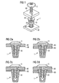
- FIGS. 2A to D show a sectional view through different attachments 80, which have been fastened by means of sterschrauben 1 to different components 90. It can be seen that the screw clip 1 can be used for a large number of different wall thicknesses of components 90 and attachments 80.
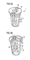
- the screw clip 1 off Fig. 1 is enlarged in the FIGS. 3A and B shown. It comprises a dowel-like screw receptacle 10, which is constructed similarly known dowel designs.
- the screw receptacle 10 has the shape of a truncated pyramid of a straight and regular pyramid, ie a straight and regular truncated pyramid, with an even number of side edges 12 and side surfaces 14 (see. Fig. 6 ).
- the hole 92 in the component 90, in which the screw clip 1 is to be inserted, is adapted to the peripheral shape of the dowel-like receptacle 10.
- the screw receptacle 10 is four-, five-, six- or eight-sided, then the hole 92 corresponding to four, five, six or eight sides and corners.
- the screw receptacle 10 and the receiving hole 92 should be adapted to each other. Therefore, the screw receptacle 10 could have a quadrangular, rectangular, square, pentagonal, hexagonal, etc., cross section. It is preferred that the truncated pyramid of the screw receptacle is formed regularly and quadratically with four side edges. In this context is it further prefers to form the truncated pyramid straight and regular with an even number of side edges.
- the screw receptacle 10 comprises four sides and has the shape of a square truncated pyramid with four side edges 12. These side edges 12 are executed according to an embodiment rounded, as shown in section in FIG Fig. 6 is shown.
- the screw receptacle 10 has a plate-shaped arrangement 40 at one end. Centered within the dish-shaped arrangement 40, a central passage opening 44 is arranged, through which the screw S is screwed into the screw receptacle 10. The plate-shaped arrangement 40 opposite end of the screw receptacle 10 is closed.
- the screw holder 10 is pierced by a franking 20.
- a franking 20 Through the franking 20, two oppositely arranged legs 30 are formed.
- the legs 30 are connected to one another at the closed end of the screw receptacle 10.
- a four-sided screw holder 10 is shown with franking 20, other constructions are conceivable.
- a six- or eight-sided screw receptacle 10 could have one or a plurality of diagonally extending indicia 20. These clearances 20 then divide the screw receptacle 10 into two or more legs 30.
- at least one franking 20 along a non-diagonal direction is also conceivable in order to produce the resilient legs 30.
- the franking 20 extends between two opposite side edges 12 in the diagonal direction of the screw holder 10.
- the franking 20 also extends into the dish-shaped arrangement 40.
- the resilient construction of the legs 30 is supported.
- the legs 30 are biased in the radial direction, so that they would spring back to a radial orientation to its original position.
- This resilient arrangement of the legs 30 is also supported by spring bars 42.
- These spring webs 42 are arranged in the plate-shaped arrangement 40. There they bridge in the circumferential direction, the at least one franking 20.
- the spring bars 42 bulge radially outward. Since the spring bars 42 want to return to their original shape, they constantly press the legs 20 radially outward. In this way, the spring bars 42 support a concern of the side surfaces 14 of the screw holder 10 on the side surfaces of the hole 92 in the component 90. Furthermore, a dimensional stability of the ringclips 1 is ensured by the spring bars 42. This plays a role precisely because, for example, in U-shaped attachments made of plastic due to different factors influencing a delay can occur. These influencing factors include spray parameters, water absorption, heat load and GF content of these plastic parts.
- the at least one franking 20 extends in the diagonal direction between two opposite side edges 12 (cf. Fig. 6 ).
- the legs 30 spring radially inward until the plate-shaped assembly 40 rests on the component 90.
- all side surfaces 14 of the screw holder 10 are supported on the respective side surfaces of the hole 92, because the legs 30 move radially outwardly due to their spring bias.
- This support of the side surfaces 14 at the hole 92 is supported by the spring forces of the spring bars 42. If the franking 20 were oriented at 45 ° at right angles to two opposite side surfaces 14, the grip between the screw clip 1 and the hole 92 would only be made via the two opposite and uninterrupted side surfaces 14. This would be disadvantageous because less holding forces of the screw 1 could be used.
- one or more of the side surfaces 14 comprise at least one undercut 16.
- Fig. 8 shows an enlarged detail Fig. 5 in which the undercuts 16 are shown.
- the undercuts 16 are arranged in a region of the screw receptacle 10 adjacent to the dish-shaped arrangement 40.
- the undercuts 16 are arranged such that they release the ringclips 1 from the hole 92 against an insertion direction E (see. Fig. 5 ) of the screw clip 1.
- a plurality of undercuts 16 are arranged on the side surfaces 14 one after the other in the insertion direction E.
- the at least one undercut 16 is located in a region adjacent to the dish-shaped arrangement 40, which tapers counter to the insertion direction E (cf. Fig. 8 ).
- a spoon-shaped oval contour 24 is provided in the franking 20. This is in Fig. 4 shown.
- this is preferably made of filled with glass fibers or made of partially aromatic polyamides. If lower stability requirements are placed on the screw clip 1, for example, a production of polypropylene or less powerful materials is conceivable.
Landscapes
- Engineering & Computer Science (AREA)
- General Engineering & Computer Science (AREA)
- Mechanical Engineering (AREA)
- Connection Of Plates (AREA)
Claims (6)
- Clip à vis (1) destiné à fixer une pièce rapportée dans un véhicule automobile à l'aide d'une vis (S), comprenant les éléments suivants :a. un logement de vis (10) du genre douille sous la forme d'un cône tronqué avec au moins quatre bords latéraux (12), lequel est fermé à une première extrémité (14) et présente un arrangement en forme de disque (40) avec un orifice de passage central (44), et lequelb. est interrompu par un dégagement (20) entre deux bords latéraux (12) du logement de vis (10), de sorte que le logement de vis du genre douille (10) comprend au moins deux branches (30) agencées de manière élastique et présentant une forme angulaire de leur côté extérieur radial, définie par deux surfaces latérales (14) adjacentes l'une à l'autre au niveau du bord latéral (12), de sorte que le clip à vis (1) peut être verrouillé respectivement par les deux surfaces latérales (14) des au moins deux branches (30), dans lequelc. les branches (30) peuvent être précontraintes par ressort par deux barrettes à ressort (42) chevauchant le dégagement (20), tandis qued. le logement de vis (10) se rétrécit par paliers dans la direction de l'arrangement en forme de disque (40), pour former au moins une contre-dépouille (16) à l'opposé d'une direction d'insertion (E) du clip à vis (1) dans une ouverture (92).
- Clip à vis (1) selon la revendication 1, dont le logement de vis (10) comporte un nombre pair de bords latéraux (12) et dont le dégagement (20) entre deux bords latéraux opposés (12) s'étend dans la diagonale par rapport à la section transversale du logement de vis (10).
- Clip à vis (1) selon la revendication 1, dont le cône tronqué est rectangulaire, de préférence carré, et comporte quatre bords latéraux (12), de préférence tronqués.
- Clip à vis (1) selon la revendication 1, dont l'arrangement en forme de disque (40) est divisé en deux moitiés par le dégagement (20), lesquelles sont reliées entre elles par les barrettes à ressort (42).
- Clip à vis (1) selon la revendication 1, dont le dégagement (20) comporte un contour ovale (24) pour la réception des tensions mécaniques.
- Vis (S) avec un clip à vis (1) selon l'une des revendications précédentes, pour la fixation d'une pièce rapportée (80) sur une pièce de construction (90).
Applications Claiming Priority (2)
| Application Number | Priority Date | Filing Date | Title |
|---|---|---|---|
| DE200820007378 DE202008007378U1 (de) | 2008-06-02 | 2008-06-02 | Schraubclip |
| PCT/EP2009/003375 WO2009146777A1 (fr) | 2008-06-02 | 2009-05-12 | Clip à vis |
Publications (2)
| Publication Number | Publication Date |
|---|---|
| EP2304250A1 EP2304250A1 (fr) | 2011-04-06 |
| EP2304250B1 true EP2304250B1 (fr) | 2013-10-09 |
Family
ID=39869199
Family Applications (1)
| Application Number | Title | Priority Date | Filing Date |
|---|---|---|---|
| EP09757161.6A Not-in-force EP2304250B1 (fr) | 2008-06-02 | 2009-05-12 | Clip à vis |
Country Status (3)
| Country | Link |
|---|---|
| EP (1) | EP2304250B1 (fr) |
| DE (1) | DE202008007378U1 (fr) |
| WO (1) | WO2009146777A1 (fr) |
Families Citing this family (4)
| Publication number | Priority date | Publication date | Assignee | Title |
|---|---|---|---|---|
| DE102010023992A1 (de) * | 2010-06-16 | 2011-12-22 | Volkswagen Ag | Anordnung zur Befestigung zumindest eines ersten Bauteils an einem zweiten Bauteil |
| DE102019109211A1 (de) * | 2019-04-08 | 2020-10-08 | Böllhoff Verbindungstechnik GmbH | Bajonettverbinder, Bauteilverbund mit diesem Bajonettverbinder, ein Herstellungsverfahren für den Bajonettverbinder sowie ein Verbindungsverfahren für mindestens zwei Bauteile mit diesem Bajonettverbinder |
| WO2020114702A1 (fr) | 2018-12-06 | 2020-06-11 | Böllhoff Verbindungstechnik GmbH | Raccord à baïonnette, pièce composite pourvue de ce raccord à baïonnette, procédé de liaison pour le raccord à baïonnette ainsi que procédé de liaison pour au moins deux pièces au moyen de ce raccord à baïonnette |
| DE102018131200A1 (de) | 2018-12-06 | 2020-06-10 | Böllhoff Verbindungstechnik GmbH | Bajonettverbinder, Bauteilverbund mit diesem Bajonettverbinder, ein Herstellungsverfahren für den Bajonettverbinder sowie ein Verbindungsverfahren für mindestens zwei Bauteile mit diesem Bajonettverbinder |
Family Cites Families (2)
| Publication number | Priority date | Publication date | Assignee | Title |
|---|---|---|---|---|
| US2836214A (en) * | 1953-07-31 | 1958-05-27 | Illinois Tool Works | Plastic screw anchor with slotted head |
| US3756116A (en) * | 1971-09-27 | 1973-09-04 | Fastway Fasteners | Plastic nut or grommet |
-
2008
- 2008-06-02 DE DE200820007378 patent/DE202008007378U1/de not_active Expired - Lifetime
-
2009
- 2009-05-12 EP EP09757161.6A patent/EP2304250B1/fr not_active Not-in-force
- 2009-05-12 WO PCT/EP2009/003375 patent/WO2009146777A1/fr active Application Filing
Also Published As
| Publication number | Publication date |
|---|---|
| DE202008007378U1 (de) | 2008-10-16 |
| WO2009146777A1 (fr) | 2009-12-10 |
| EP2304250A1 (fr) | 2011-04-06 |
Similar Documents
| Publication | Publication Date | Title |
|---|---|---|
| EP3329132B1 (fr) | Accouplement emboîtable en deux parties servant à l'assemblage de pièces | |
| DE2243661B2 (de) | Vorrichtung zum Befestigen einer Platte an einem Bauteil, insbesondere von Verkleidungsplatten im Flugzeugbau | |
| EP0641939A1 (fr) | Dispositif de fixation | |
| DE3710838A1 (de) | Bajonettverschluss | |
| EP2678571A1 (fr) | Dispositif d'assemblage d'angle pour profilés creux | |
| DE19545069B4 (de) | Stoßstange mit Querträger in Halbschalenbauweise | |
| DE10064017A1 (de) | Vorrichtung zur Verbindung eines Trägers, insbesondere eines Karosserieteils eines Kraftfahrzeuges, mit einem Plattenelement, insbesondere einer Tür- oder Wandverkleidung | |
| DE19921613C2 (de) | Verbindungselement | |
| EP0636798B1 (fr) | Elément de fixation rotatif | |
| EP3478975B1 (fr) | Clip doté d'une tête et d'une tige s'étendant le long d'un axe longitudinal à partir de la tête | |
| EP2304250B1 (fr) | Clip à vis | |
| EP0685403B1 (fr) | Dispositif de connection | |
| WO2013153091A1 (fr) | Support de toit pour un porte-bagages de toit pouvant être fixé sur celui-ci | |
| EP2767659B1 (fr) | Guide à barres rondes réglable en hauteur | |
| DE102019111237A1 (de) | Zweiteilige Schraubenmutter mit hoher Andrückkraft | |
| DE9306773U1 (de) | Befestigungsvorrichtung aus Kunststoff, insbesondere für Platinen | |
| DE69305423T2 (de) | Verkehrszeichen | |
| EP3045743A1 (fr) | Fixation de structure porteuse pour un repartiteur de fluide, agencement de montage et procede de montage d'un repartiteur de fluide | |
| WO2020225079A1 (fr) | Dispositif d'assemblage et meuble | |
| DE2058668B2 (de) | Befestigungselement | |
| EP1134170A1 (fr) | Structure à assemblage modulaire pour des rayons de stockage | |
| DE29603389U1 (de) | Schnellverschluß | |
| DE102018114585A1 (de) | Schubkasten und Verfahren zur Montage einer Rückwand an einer Seitenzarge eines Schubkastens | |
| DE9004757U1 (de) | Stangenführung für die Stangen eines Stangenverschlußes | |
| DE102015119991A1 (de) | Haltevorrichtung für einen Regalboden an einer Regalwand und Regal mit einer solchen Haltevorrichtung |
Legal Events
| Date | Code | Title | Description |
|---|---|---|---|
| PUAI | Public reference made under article 153(3) epc to a published international application that has entered the european phase |
Free format text: ORIGINAL CODE: 0009012 |
|
| 17P | Request for examination filed |
Effective date: 20101222 |
|
| AK | Designated contracting states |
Kind code of ref document: A1 Designated state(s): AT BE BG CH CY CZ DE DK EE ES FI FR GB GR HR HU IE IS IT LI LT LU LV MC MK MT NL NO PL PT RO SE SI SK TR |
|
| AX | Request for extension of the european patent |
Extension state: AL BA RS |
|
| DAX | Request for extension of the european patent (deleted) | ||
| GRAP | Despatch of communication of intention to grant a patent |
Free format text: ORIGINAL CODE: EPIDOSNIGR1 |
|
| INTG | Intention to grant announced |
Effective date: 20130429 |
|
| GRAS | Grant fee paid |
Free format text: ORIGINAL CODE: EPIDOSNIGR3 |
|
| GRAA | (expected) grant |
Free format text: ORIGINAL CODE: 0009210 |
|
| AK | Designated contracting states |
Kind code of ref document: B1 Designated state(s): AT BE BG CH CY CZ DE DK EE ES FI FR GB GR HR HU IE IS IT LI LT LU LV MC MK MT NL NO PL PT RO SE SI SK TR |
|
| REG | Reference to a national code |
Ref country code: GB Ref legal event code: FG4D Free format text: NOT ENGLISH |
|
| REG | Reference to a national code |
Ref country code: CH Ref legal event code: EP Ref country code: AT Ref legal event code: REF Ref document number: 635692 Country of ref document: AT Kind code of ref document: T Effective date: 20131015 |
|
| REG | Reference to a national code |
Ref country code: IE Ref legal event code: FG4D Free format text: LANGUAGE OF EP DOCUMENT: GERMAN |
|
| REG | Reference to a national code |
Ref country code: DE Ref legal event code: R096 Ref document number: 502009008138 Country of ref document: DE Effective date: 20131205 |
|
| REG | Reference to a national code |
Ref country code: NL Ref legal event code: VDEP Effective date: 20131009 |
|
| PG25 | Lapsed in a contracting state [announced via postgrant information from national office to epo] |
Ref country code: SI Free format text: LAPSE BECAUSE OF FAILURE TO SUBMIT A TRANSLATION OF THE DESCRIPTION OR TO PAY THE FEE WITHIN THE PRESCRIBED TIME-LIMIT Effective date: 20131009 |
|
| REG | Reference to a national code |
Ref country code: LT Ref legal event code: MG4D |
|
| REG | Reference to a national code |
Ref country code: DE Ref legal event code: R082 Ref document number: 502009008138 Country of ref document: DE Representative=s name: HEYER, VOLKER, DIPL.-PHYS. DR.RER.NAT., DE Ref country code: DE Ref legal event code: R082 Ref document number: 502009008138 Country of ref document: DE Representative=s name: BOCKHORNI & KOLLEGEN PATENT- UND RECHTSANWAELT, DE |
|
| PG25 | Lapsed in a contracting state [announced via postgrant information from national office to epo] |
Ref country code: LT Free format text: LAPSE BECAUSE OF FAILURE TO SUBMIT A TRANSLATION OF THE DESCRIPTION OR TO PAY THE FEE WITHIN THE PRESCRIBED TIME-LIMIT Effective date: 20131009 Ref country code: IS Free format text: LAPSE BECAUSE OF FAILURE TO SUBMIT A TRANSLATION OF THE DESCRIPTION OR TO PAY THE FEE WITHIN THE PRESCRIBED TIME-LIMIT Effective date: 20140209 Ref country code: NO Free format text: LAPSE BECAUSE OF FAILURE TO SUBMIT A TRANSLATION OF THE DESCRIPTION OR TO PAY THE FEE WITHIN THE PRESCRIBED TIME-LIMIT Effective date: 20140109 Ref country code: SE Free format text: LAPSE BECAUSE OF FAILURE TO SUBMIT A TRANSLATION OF THE DESCRIPTION OR TO PAY THE FEE WITHIN THE PRESCRIBED TIME-LIMIT Effective date: 20131009 Ref country code: HR Free format text: LAPSE BECAUSE OF FAILURE TO SUBMIT A TRANSLATION OF THE DESCRIPTION OR TO PAY THE FEE WITHIN THE PRESCRIBED TIME-LIMIT Effective date: 20131009 Ref country code: FI Free format text: LAPSE BECAUSE OF FAILURE TO SUBMIT A TRANSLATION OF THE DESCRIPTION OR TO PAY THE FEE WITHIN THE PRESCRIBED TIME-LIMIT Effective date: 20131009 Ref country code: NL Free format text: LAPSE BECAUSE OF FAILURE TO SUBMIT A TRANSLATION OF THE DESCRIPTION OR TO PAY THE FEE WITHIN THE PRESCRIBED TIME-LIMIT Effective date: 20131009 |
|
| REG | Reference to a national code |
Ref country code: DE Ref legal event code: R082 Ref document number: 502009008138 Country of ref document: DE Representative=s name: HEYER, VOLKER, DIPL.-PHYS. DR.RER.NAT., DE |
|
| PG25 | Lapsed in a contracting state [announced via postgrant information from national office to epo] |
Ref country code: LV Free format text: LAPSE BECAUSE OF FAILURE TO SUBMIT A TRANSLATION OF THE DESCRIPTION OR TO PAY THE FEE WITHIN THE PRESCRIBED TIME-LIMIT Effective date: 20131009 Ref country code: PL Free format text: LAPSE BECAUSE OF FAILURE TO SUBMIT A TRANSLATION OF THE DESCRIPTION OR TO PAY THE FEE WITHIN THE PRESCRIBED TIME-LIMIT Effective date: 20131009 Ref country code: ES Free format text: LAPSE BECAUSE OF FAILURE TO SUBMIT A TRANSLATION OF THE DESCRIPTION OR TO PAY THE FEE WITHIN THE PRESCRIBED TIME-LIMIT Effective date: 20131009 Ref country code: CY Free format text: LAPSE BECAUSE OF FAILURE TO SUBMIT A TRANSLATION OF THE DESCRIPTION OR TO PAY THE FEE WITHIN THE PRESCRIBED TIME-LIMIT Effective date: 20131009 |
|
| PG25 | Lapsed in a contracting state [announced via postgrant information from national office to epo] |
Ref country code: PT Free format text: LAPSE BECAUSE OF FAILURE TO SUBMIT A TRANSLATION OF THE DESCRIPTION OR TO PAY THE FEE WITHIN THE PRESCRIBED TIME-LIMIT Effective date: 20140210 |
|
| REG | Reference to a national code |
Ref country code: DE Ref legal event code: R097 Ref document number: 502009008138 Country of ref document: DE |
|
| PG25 | Lapsed in a contracting state [announced via postgrant information from national office to epo] |
Ref country code: EE Free format text: LAPSE BECAUSE OF FAILURE TO SUBMIT A TRANSLATION OF THE DESCRIPTION OR TO PAY THE FEE WITHIN THE PRESCRIBED TIME-LIMIT Effective date: 20131009 |
|
| PLBE | No opposition filed within time limit |
Free format text: ORIGINAL CODE: 0009261 |
|
| STAA | Information on the status of an ep patent application or granted ep patent |
Free format text: STATUS: NO OPPOSITION FILED WITHIN TIME LIMIT |
|
| PG25 | Lapsed in a contracting state [announced via postgrant information from national office to epo] |
Ref country code: SK Free format text: LAPSE BECAUSE OF FAILURE TO SUBMIT A TRANSLATION OF THE DESCRIPTION OR TO PAY THE FEE WITHIN THE PRESCRIBED TIME-LIMIT Effective date: 20131009 Ref country code: RO Free format text: LAPSE BECAUSE OF FAILURE TO SUBMIT A TRANSLATION OF THE DESCRIPTION OR TO PAY THE FEE WITHIN THE PRESCRIBED TIME-LIMIT Effective date: 20131009 Ref country code: CZ Free format text: LAPSE BECAUSE OF FAILURE TO SUBMIT A TRANSLATION OF THE DESCRIPTION OR TO PAY THE FEE WITHIN THE PRESCRIBED TIME-LIMIT Effective date: 20131009 Ref country code: IT Free format text: LAPSE BECAUSE OF FAILURE TO SUBMIT A TRANSLATION OF THE DESCRIPTION OR TO PAY THE FEE WITHIN THE PRESCRIBED TIME-LIMIT Effective date: 20131009 |
|
| 26N | No opposition filed |
Effective date: 20140710 |
|
| PG25 | Lapsed in a contracting state [announced via postgrant information from national office to epo] |
Ref country code: DK Free format text: LAPSE BECAUSE OF FAILURE TO SUBMIT A TRANSLATION OF THE DESCRIPTION OR TO PAY THE FEE WITHIN THE PRESCRIBED TIME-LIMIT Effective date: 20131009 |
|
| REG | Reference to a national code |
Ref country code: DE Ref legal event code: R097 Ref document number: 502009008138 Country of ref document: DE Effective date: 20140710 |
|
| PG25 | Lapsed in a contracting state [announced via postgrant information from national office to epo] |
Ref country code: LU Free format text: LAPSE BECAUSE OF FAILURE TO SUBMIT A TRANSLATION OF THE DESCRIPTION OR TO PAY THE FEE WITHIN THE PRESCRIBED TIME-LIMIT Effective date: 20140512 |
|
| REG | Reference to a national code |
Ref country code: CH Ref legal event code: PL |
|
| GBPC | Gb: european patent ceased through non-payment of renewal fee |
Effective date: 20140512 |
|
| PG25 | Lapsed in a contracting state [announced via postgrant information from national office to epo] |
Ref country code: LI Free format text: LAPSE BECAUSE OF NON-PAYMENT OF DUE FEES Effective date: 20140531 Ref country code: MC Free format text: LAPSE BECAUSE OF FAILURE TO SUBMIT A TRANSLATION OF THE DESCRIPTION OR TO PAY THE FEE WITHIN THE PRESCRIBED TIME-LIMIT Effective date: 20131009 Ref country code: CH Free format text: LAPSE BECAUSE OF NON-PAYMENT OF DUE FEES Effective date: 20140531 |
|
| REG | Reference to a national code |
Ref country code: IE Ref legal event code: MM4A |
|
| REG | Reference to a national code |
Ref country code: FR Ref legal event code: ST Effective date: 20150130 |
|
| PG25 | Lapsed in a contracting state [announced via postgrant information from national office to epo] |
Ref country code: IE Free format text: LAPSE BECAUSE OF NON-PAYMENT OF DUE FEES Effective date: 20140512 |
|
| PG25 | Lapsed in a contracting state [announced via postgrant information from national office to epo] |
Ref country code: FR Free format text: LAPSE BECAUSE OF NON-PAYMENT OF DUE FEES Effective date: 20140602 Ref country code: GB Free format text: LAPSE BECAUSE OF NON-PAYMENT OF DUE FEES Effective date: 20140512 |
|
| REG | Reference to a national code |
Ref country code: AT Ref legal event code: MM01 Ref document number: 635692 Country of ref document: AT Kind code of ref document: T Effective date: 20140512 |
|
| PG25 | Lapsed in a contracting state [announced via postgrant information from national office to epo] |
Ref country code: AT Free format text: LAPSE BECAUSE OF NON-PAYMENT OF DUE FEES Effective date: 20140512 |
|
| PG25 | Lapsed in a contracting state [announced via postgrant information from national office to epo] |
Ref country code: MT Free format text: LAPSE BECAUSE OF FAILURE TO SUBMIT A TRANSLATION OF THE DESCRIPTION OR TO PAY THE FEE WITHIN THE PRESCRIBED TIME-LIMIT Effective date: 20131009 |
|
| PG25 | Lapsed in a contracting state [announced via postgrant information from national office to epo] |
Ref country code: GR Free format text: LAPSE BECAUSE OF FAILURE TO SUBMIT A TRANSLATION OF THE DESCRIPTION OR TO PAY THE FEE WITHIN THE PRESCRIBED TIME-LIMIT Effective date: 20140110 Ref country code: BG Free format text: LAPSE BECAUSE OF FAILURE TO SUBMIT A TRANSLATION OF THE DESCRIPTION OR TO PAY THE FEE WITHIN THE PRESCRIBED TIME-LIMIT Effective date: 20131009 |
|
| PG25 | Lapsed in a contracting state [announced via postgrant information from national office to epo] |
Ref country code: BE Free format text: LAPSE BECAUSE OF FAILURE TO SUBMIT A TRANSLATION OF THE DESCRIPTION OR TO PAY THE FEE WITHIN THE PRESCRIBED TIME-LIMIT Effective date: 20140531 Ref country code: TR Free format text: LAPSE BECAUSE OF FAILURE TO SUBMIT A TRANSLATION OF THE DESCRIPTION OR TO PAY THE FEE WITHIN THE PRESCRIBED TIME-LIMIT Effective date: 20131009 Ref country code: HU Free format text: LAPSE BECAUSE OF FAILURE TO SUBMIT A TRANSLATION OF THE DESCRIPTION OR TO PAY THE FEE WITHIN THE PRESCRIBED TIME-LIMIT; INVALID AB INITIO Effective date: 20090512 |
|
| PG25 | Lapsed in a contracting state [announced via postgrant information from national office to epo] |
Ref country code: MK Free format text: LAPSE BECAUSE OF FAILURE TO SUBMIT A TRANSLATION OF THE DESCRIPTION OR TO PAY THE FEE WITHIN THE PRESCRIBED TIME-LIMIT Effective date: 20131009 |
|
| PGFP | Annual fee paid to national office [announced via postgrant information from national office to epo] |
Ref country code: DE Payment date: 20200729 Year of fee payment: 12 |
|
| REG | Reference to a national code |
Ref country code: DE Ref legal event code: R119 Ref document number: 502009008138 Country of ref document: DE |
|
| PG25 | Lapsed in a contracting state [announced via postgrant information from national office to epo] |
Ref country code: DE Free format text: LAPSE BECAUSE OF NON-PAYMENT OF DUE FEES Effective date: 20211201 |