EP1323932B1 - Dispositif destine a l'assemblage d'un panneau sur une plaque de support - Google Patents
Dispositif destine a l'assemblage d'un panneau sur une plaque de support Download PDFInfo
- Publication number
- EP1323932B1 EP1323932B1 EP00966173A EP00966173A EP1323932B1 EP 1323932 B1 EP1323932 B1 EP 1323932B1 EP 00966173 A EP00966173 A EP 00966173A EP 00966173 A EP00966173 A EP 00966173A EP 1323932 B1 EP1323932 B1 EP 1323932B1
- Authority
- EP
- European Patent Office
- Prior art keywords
- support plate
- panel
- female part
- male part
- tabs
- Prior art date
- Legal status (The legal status is an assumption and is not a legal conclusion. Google has not performed a legal analysis and makes no representation as to the accuracy of the status listed.)
- Expired - Lifetime
Links
- 238000000926 separation method Methods 0.000 claims abstract description 10
- 238000006073 displacement reaction Methods 0.000 claims abstract description 8
- 230000015572 biosynthetic process Effects 0.000 claims abstract description 4
- 230000002093 peripheral effect Effects 0.000 claims description 20
- 238000007789 sealing Methods 0.000 claims description 6
- 238000005266 casting Methods 0.000 claims description 4
- 230000014759 maintenance of location Effects 0.000 claims description 4
- 238000000465 moulding Methods 0.000 claims description 3
- 230000002708 enhancing effect Effects 0.000 claims 1
- 230000000717 retained effect Effects 0.000 abstract 1
- 230000037431 insertion Effects 0.000 description 3
- 238000003780 insertion Methods 0.000 description 3
- 230000008878 coupling Effects 0.000 description 2
- 238000010168 coupling process Methods 0.000 description 2
- 238000005859 coupling reaction Methods 0.000 description 2
- 238000002347 injection Methods 0.000 description 2
- 239000007924 injection Substances 0.000 description 2
- 239000000463 material Substances 0.000 description 2
- 238000005452 bending Methods 0.000 description 1
- 230000000295 complement effect Effects 0.000 description 1
- 238000001746 injection moulding Methods 0.000 description 1
- 239000002184 metal Substances 0.000 description 1
- 230000002787 reinforcement Effects 0.000 description 1
- 230000000284 resting effect Effects 0.000 description 1
Images

Classifications
-
- F—MECHANICAL ENGINEERING; LIGHTING; HEATING; WEAPONS; BLASTING
- F16—ENGINEERING ELEMENTS AND UNITS; GENERAL MEASURES FOR PRODUCING AND MAINTAINING EFFECTIVE FUNCTIONING OF MACHINES OR INSTALLATIONS; THERMAL INSULATION IN GENERAL
- F16B—DEVICES FOR FASTENING OR SECURING CONSTRUCTIONAL ELEMENTS OR MACHINE PARTS TOGETHER, e.g. NAILS, BOLTS, CIRCLIPS, CLAMPS, CLIPS OR WEDGES; JOINTS OR JOINTING
- F16B5/00—Joining sheets or plates, e.g. panels, to one another or to strips or bars parallel to them
- F16B5/06—Joining sheets or plates, e.g. panels, to one another or to strips or bars parallel to them by means of clamps or clips
- F16B5/0607—Joining sheets or plates, e.g. panels, to one another or to strips or bars parallel to them by means of clamps or clips joining sheets or plates to each other
- F16B5/0621—Joining sheets or plates, e.g. panels, to one another or to strips or bars parallel to them by means of clamps or clips joining sheets or plates to each other in parallel relationship
- F16B5/065—Joining sheets or plates, e.g. panels, to one another or to strips or bars parallel to them by means of clamps or clips joining sheets or plates to each other in parallel relationship the plates being one on top of the other and distanced from each other, e.g. by using protrusions to keep contact and distance
-
- B—PERFORMING OPERATIONS; TRANSPORTING
- B60—VEHICLES IN GENERAL
- B60R—VEHICLES, VEHICLE FITTINGS, OR VEHICLE PARTS, NOT OTHERWISE PROVIDED FOR
- B60R13/00—Elements for body-finishing, identifying, or decorating; Arrangements or adaptations for advertising purposes
- B60R13/02—Internal Trim mouldings ; Internal Ledges; Wall liners for passenger compartments; Roof liners
- B60R13/0206—Arrangements of fasteners and clips specially adapted for attaching inner vehicle liners or mouldings
-
- F—MECHANICAL ENGINEERING; LIGHTING; HEATING; WEAPONS; BLASTING
- F16—ENGINEERING ELEMENTS AND UNITS; GENERAL MEASURES FOR PRODUCING AND MAINTAINING EFFECTIVE FUNCTIONING OF MACHINES OR INSTALLATIONS; THERMAL INSULATION IN GENERAL
- F16B—DEVICES FOR FASTENING OR SECURING CONSTRUCTIONAL ELEMENTS OR MACHINE PARTS TOGETHER, e.g. NAILS, BOLTS, CIRCLIPS, CLAMPS, CLIPS OR WEDGES; JOINTS OR JOINTING
- F16B21/00—Means for preventing relative axial movement of a pin, spigot, shaft or the like and a member surrounding it; Stud-and-socket releasable fastenings
- F16B21/06—Releasable fastening devices with snap-action
- F16B21/07—Releasable fastening devices with snap-action in which the socket has a resilient part
- F16B21/073—Releasable fastening devices with snap-action in which the socket has a resilient part the socket having a resilient part on its inside
- F16B21/075—Releasable fastening devices with snap-action in which the socket has a resilient part the socket having a resilient part on its inside the socket having resilient parts on its inside and outside
-
- F—MECHANICAL ENGINEERING; LIGHTING; HEATING; WEAPONS; BLASTING
- F16—ENGINEERING ELEMENTS AND UNITS; GENERAL MEASURES FOR PRODUCING AND MAINTAINING EFFECTIVE FUNCTIONING OF MACHINES OR INSTALLATIONS; THERMAL INSULATION IN GENERAL
- F16B—DEVICES FOR FASTENING OR SECURING CONSTRUCTIONAL ELEMENTS OR MACHINE PARTS TOGETHER, e.g. NAILS, BOLTS, CIRCLIPS, CLAMPS, CLIPS OR WEDGES; JOINTS OR JOINTING
- F16B21/00—Means for preventing relative axial movement of a pin, spigot, shaft or the like and a member surrounding it; Stud-and-socket releasable fastenings
- F16B21/06—Releasable fastening devices with snap-action
- F16B21/08—Releasable fastening devices with snap-action in which the stud, pin, or spigot has a resilient part
-
- F—MECHANICAL ENGINEERING; LIGHTING; HEATING; WEAPONS; BLASTING
- F16—ENGINEERING ELEMENTS AND UNITS; GENERAL MEASURES FOR PRODUCING AND MAINTAINING EFFECTIVE FUNCTIONING OF MACHINES OR INSTALLATIONS; THERMAL INSULATION IN GENERAL
- F16B—DEVICES FOR FASTENING OR SECURING CONSTRUCTIONAL ELEMENTS OR MACHINE PARTS TOGETHER, e.g. NAILS, BOLTS, CIRCLIPS, CLAMPS, CLIPS OR WEDGES; JOINTS OR JOINTING
- F16B5/00—Joining sheets or plates, e.g. panels, to one another or to strips or bars parallel to them
- F16B5/06—Joining sheets or plates, e.g. panels, to one another or to strips or bars parallel to them by means of clamps or clips
- F16B5/0607—Joining sheets or plates, e.g. panels, to one another or to strips or bars parallel to them by means of clamps or clips joining sheets or plates to each other
- F16B5/0621—Joining sheets or plates, e.g. panels, to one another or to strips or bars parallel to them by means of clamps or clips joining sheets or plates to each other in parallel relationship
- F16B5/0628—Joining sheets or plates, e.g. panels, to one another or to strips or bars parallel to them by means of clamps or clips joining sheets or plates to each other in parallel relationship allowing for adjustment parallel or perpendicular to the plane of the sheets or plates
-
- F—MECHANICAL ENGINEERING; LIGHTING; HEATING; WEAPONS; BLASTING
- F16—ENGINEERING ELEMENTS AND UNITS; GENERAL MEASURES FOR PRODUCING AND MAINTAINING EFFECTIVE FUNCTIONING OF MACHINES OR INSTALLATIONS; THERMAL INSULATION IN GENERAL
- F16B—DEVICES FOR FASTENING OR SECURING CONSTRUCTIONAL ELEMENTS OR MACHINE PARTS TOGETHER, e.g. NAILS, BOLTS, CIRCLIPS, CLAMPS, CLIPS OR WEDGES; JOINTS OR JOINTING
- F16B5/00—Joining sheets or plates, e.g. panels, to one another or to strips or bars parallel to them
- F16B5/06—Joining sheets or plates, e.g. panels, to one another or to strips or bars parallel to them by means of clamps or clips
- F16B5/0607—Joining sheets or plates, e.g. panels, to one another or to strips or bars parallel to them by means of clamps or clips joining sheets or plates to each other
- F16B5/0621—Joining sheets or plates, e.g. panels, to one another or to strips or bars parallel to them by means of clamps or clips joining sheets or plates to each other in parallel relationship
- F16B5/0657—Joining sheets or plates, e.g. panels, to one another or to strips or bars parallel to them by means of clamps or clips joining sheets or plates to each other in parallel relationship at least one of the plates providing a raised structure, e.g. of the doghouse type, for connection with the clamps or clips of the other plate
Definitions
- the present invention relates to a device for fixing together a panel and a support plate, and more specifically to a clip or clamp used to fix an internal or external lining of the body of a vehicle, wherein the panel and the plate or body are set parallel or nearly parallel to each other, and practically against each other or with a small separation.
- the object of the invention is to provide a fixing clip or clamp that, in addition to acting as such and insuring the tightness of the union, allows to adjust the separation between the panel and the plate acting as support, as well as to disassemble them without difficulty, thereby recovering the device or clip for a possible re-utilization.
- PCT ES 99/00324 describes a fixing clip for plates, preferably and especially applicable for fixing an inner lining panel for a vehicle body, clip which comprises a single piece of plastic complemented by a plastic flange that is moulded from a casting on the single piece, obtained previously by injection moulding.
- the single piece has a header for coupling it to the panel and a peripheral groove on said header for inserting the flange, the latter determining the corresponding sealing element. Additionally, the single piece also comprises a locking core that can contract elastically and is meant to couple in the orifice of the support plate, corresponding naturally to the metal body, in the case of a vehicle, with said locking core having side arms that provide it with the required elasticity, in a trunco-conical arrangement, to facilitate the insertion of the said core in the fixing orifice of the support plate of the vehicle body.
- the clamp described does not allow adjusting the separation between the panel and the support plate, which on occasion is necessary.
- a fastener for releasably securing first and second panels together is disclosed in patent US-5.507.610 , which comprises a pin for being secured in an opening of a first panel, and a grommet for being secured in an opening of the second panel and for releasable receiving a shank of the pin to thereby releasably secure first and second panels together.
- the pin and the grommet are not extracted together, instead the pin is detached from the grommet in such a way that the pin remains attached to the first panel 11 while the grommet remains seated in the opening of the second panel.
- the device of the invention consists of a clip or clamp for fixing a panel and a support plate, with the special characteristic that its structure allows adjusting the separation between the panel and the support plate, as well as a simple disassembly, which allows a possible re-utilization.
- the device of the invention is characterised firstly in that it comprises two parts joined to each other by pressure, one having the function a male part and the other the function of a female part especially as the invention relates to a device of the type disclosed in US-A-5507610 and having the features recited in claim 1.
- the male part comprises an elongated body in the form of a shaft, on one of whose ends is provided the corresponding header for fixing it to the panel, while the rest of said part determines a segment with peripheral sawtooth projections which will allow adjusting the separation between the panel and the support plate, as the female part is joined to the male part so that they move relative to each other, and it is the female part that passes through the orifice of the support plate and is locked in it.
- further projections or tabs are provided with several functions, some to retain the female part on the male part and thereby prevent the adjustment from taking place before the assembly; others, specifically the tabs, to retain the female and male part on each other to allow the former to be carried when the male part is pulled out during disassembly; others to ensure a proper relative position of the two parts before the assembly is installed, etc.
- a further characteristic of the said male part is its conical configuration, in the form of a cap, on the end opposite the header, which configuration determines a self-centring means during the assembly to prevent possible offsets between the orifices, the body support plate and the position of the device or clip in the panel. It also allows moving the female part during disassembly.
- the female part it comprises an elastic core or body that is determined by side arms which configure said part, all according to a trunco-conical configuration to allow its insertion in the orifice of the support plate, with the free end of said arms having tabs for locking on the peripheral projections of the male part, in order to allow adjusting the displacement of one part with respect to the other, and therefore the panel with respect to the support plate comprised by the vehicle body when this is the application of the device.
- Said female part comprises, as is conventional, a sealing and stop suction cup in its assembly on the corresponding orifice of the support plate or body itself, including a conical configuration of its upper opening to facilitate the entry of the corresponding flanges of the male part.
- the device can be complemented with a soft plastic washer mounted around the perimeter of the suction cup to improve the seal provided, which washer would be incorporated by moulding or injection from a casting.
- the tabs provided on the end opposite the locking end of said part which constitute the means for adjusting the displacement of said female part with respect to the male part, are offset in height in order to halve the distance between each pair of peripheral sawtooth projections of the male part.
- the female part is provided near the end where said tabs are provided with grooves that allow the tabs to bend in one sense and in addition to achieve the locking onto the male part.
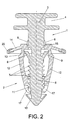
- the device disclosed comprises two parts (1) and (2) that are joined to each other by pressure, with both parts obtained by injection of a relatively hard plastic material.
- the part (1) hereinafter referred to as the male part, is provided on one of its ends with a header (3), which in turn has a groove (4) for coupling it onto the panel (5), specifically on a turret of said panel (5) to which it must be fixed.
- said male part (1) determines an elongated shaft form with a segment (6) that is provided with a number of peripheral sawtooth projections (7); with the specific characteristic that between the header (3) and the sawtooth segment (7) are provided flanges (8) and tabs (9) that project laterally and diverge in an upward sense, the function of which will be explained below.
- the end opposite the header (3) has a conical configuration (10) in the form of a cap, while between this conical formation (10) and the other segment (6) there is a straight peripheral projection (11).
- part (2) hereinafter referred to as the female part, it is provided with lateral elastic arms (12) having a trunco-conical configuration, with a peripheral lip (13) and a sealing suction cup (14) in correspondence with one of its ends, in which is defined an opening for inserting the shaft of the male part (1); a conical segment (15) is provided at this opening to facilitate the entry or passage of the flanges (8) of the male part (1).
- the elastic arms (12) of the female part (2) determine a trunco-conical configuration that allows its insertion in the corresponding orifice of the support plate (16) corresponding to the body of a vehicle, on which the panel (5) is to be fixed.
- elastic tabs (17) that constitute the means for adjusting the relative displacement between the male part (1) and the female part (2), so that said elastic tabs (17) tend to lock in the peripheral projections (7) that define the toothing of the male part (1); such that said elastic parts (17) are offset in height in order to halve the distance between the pair of projections (7) that define the toothed segment (6) of the male part (1).
- the lateral elastic arms (12) of the female part (2) are provided with reinforcement ribs (18), while near the end provided with the tabs (17) said arms have grooves (19) that allow bending said tabs (17).
- the device can be complemented with a washer (20) made of a soft plastic material, incorporated by moulding or injecting from a casting on the peripheral edge of the suction cup (14), thereby increasing the tightness provided by the latter.
- the operation of the device is as follows:
- the device is supplied as shown in figure 2, that is, with the female part (2) placed in the lowermost area of the male part (1), with the tabs (17) closed in the resting position.
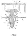
- the device is mounted through the groove (4) of the male part (1) on the panel (5), and through the female part (2) on the support plate (16), until the suction cup (14) meets the surface of said plate, so that the female plate (2) is locked in the corresponding orifice of the support plate (16) by the peripheral lip (13) of the said female part (2), which meets the opposing part of the aforementioned support plate (16).
- the flanges (8) and the circular ring (11) are provided, such that the force required to insert these is greater than that required to insert the lateral arms (12) of the female part (2).
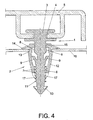
- Disassembly can be easily performed, thereby allowing to reuse the device.
- the male part (1) must be pulled in the sense indicated by the arrow of figure 4, so that as it is pulled it carries the female part (2), since the flanges (8) and the oblique tabs (9), the peripheral lip (11) or the projections (7) and the conical configuration (10) of the male part (1) constitute retention means for the female part (2), carrying the latter when the male part (1) is pulled on and extracted.
- the flanges (8), tabs (9), projections (11) or projections (7) and the conical configuration (10) are spaced along the shaft that constitutes the male part (1) such that when the female part (2) is pulled and its tabs (17) pass one of the aforementioned elements, retention is provided by the following element (flange, tab, peripheral projection, projections and conical configuration).
- the peripheral projection (11) is straight and in addition to the aforementioned retaining functions it determines the starting axis for the toothing formed by the sawtooth projections (7).
- the conical form (10) of the end of the male part (1) also constitutes a means of retention of the female part (2) for carrying the latter, if for any reason the tabs (17) of said female part (2) pass beyond the peripheral projection (11) during their displacement, and further prevent the adjustment from occurring before the device is assembled, as if said end conical configuration (10) were not present the female part (2) could be displaced by the toothed segment of the male part (1), which would prevent its motion in the opposite sense unless a great force were exerted, which could lead to damaging or breaking a component.
Landscapes
- Engineering & Computer Science (AREA)
- General Engineering & Computer Science (AREA)
- Mechanical Engineering (AREA)
- Insertion Pins And Rivets (AREA)
- Vehicle Step Arrangements And Article Storage (AREA)
- Connection Of Plates (AREA)
Claims (7)
- Dispositif pour fixer ensemble un panneau (5) et un plaque de support (16), de préférence conçu pour fixer un panneau de revêtement interne ou externe à la carrosserie correspondante du véhicule, le dispositif comprenant une pièce mâle (1) et une pièce femelle (2) qui sont indépendantes et qui peuvent s'accoupler l'une à l'autre à pression, la pièce mâle (1) étant pourvue d'une bouterolle (3) pour s'assembler au panneau (5), tandis que la pièce femelle (2) est pourvue de bras élastiques (12) déterminant une pièce tronconique pour s'assembler sur la plaque de support (16), dans laquelle la pièce mâle (1) a une forme allongée sous forme d'un arbre, et ils définissent dans une zone intermédiaire un segment denté (6) pourvu de saillies périphériques sous forme de dents de scie (7), sur lesquelles tombent des pattes élastiques (17) prévues à cet effet à l'extrémité correspondante de la pièce femelle (2), pour permettre d'ajuster le déplacement relatif desdits pièces (1) et (2) et par conséquent la séparation du panneau (5) de la plaque de support (16), caractérisé en ce que la pièce mâle (1) est pourvue de moyens de retenue (8,9,11,7,10) pour que la pièce mâle (2) soit portée par la pièce mâle (1) lorsque cette dernière est sortie pendant le désassemblage du dispositif, la pièce femelle (2) étant pourvue d'une ventouse d'étanchéité (14) à une de ses extrémités, qui fournit un contact intime avec la surface de la plaque de support (16).
- Dispositif pour fixer ensemble un panneau et une plaque de support, selon la revendication 1, caractérisé en ce que la pièce mâle (1) est prévue entre la bouterolle (3) et le segment denté (6) avec des rebords (8) et des pattes obliques (9) qui divergent et saillissent extérieurement, décalées en hauteur par rapport audit rebords (8), qui définissent les moyens pour porter la pièce femelle (2); de manière que ladite pièce (1 ) soit prévue en outre, à l'extrémité en regard de la bouterolle (3) avec une formation conique (10) sous forme de capsule, de manière qu'entre cette formation et le segment denté (6) soit prévu une saillie droite périphérique (11 ) qui détermine des moyens additionnels pour porter la pièce femelle (2) lors du désassemblage du dispositif ou unité.
- Dispositif pour fixer ensemble un panneau et une plaque de support selon les revendications antérieures, caractérisé en ce que la pièce femelle (2) est prévue à une extrémité qui a les pattes élastiques (17) avec des rainures (18) appropriées pour pourvoir de l'élasticité audites pattes (17).
- Dispositif pour fixer ensemble un panneau et une plaque de support, selon les revendications antérieures, caractérisé en ce que l'ouverture de la pièce femelle (2) dans laquelle est inséré l'arbre de la pièce mâle (1) est pourvue d'un segment tronconique (15) qui permet le passage des saillies (8) de ladite pièce mâle (1).
- Dispositif pour fixer ensemble un panneau et une plaque de support, selon les revendications antérieures, caractérisé en ce que les pattes élastiques (17) de la pièce femelle (2) sont décalées en hauteur par couples afin de réduire la séparation entre les saillies périphériques (7) qui déterminent le segment denté (6) de la pièce mâle (1).
- Dispositif pour fixer ensemble un panneau et une plaque de support, selon les revendications antérieures, caractérisé en ce que la ventouse d'étanchéité (14), sous forme d'un rebord ou lèvre périphérique de la pièce femelle (2) peut être complémentée périphériquement par une rondelle (20) en plastique mou qui est incorporée par moulage ou injection à partir d'une coulée, en constituant un moyen pour améliorer l'étanchéité de la ventouse (14).
- Dispositif pour fixer ensemble un panneau et une plaque de support, selon les revendications antérieures, caractérisé en ce que la plaque de support (16) est mise en place entre la ventouse (14) et une lèvre périphérique (13) qui est définie à une extrémité des bras élastiques (12), la pièce femelle (2) étant alors bloquée dans l'orifice correspondant de la plaque de support (16).
Applications Claiming Priority (1)
| Application Number | Priority Date | Filing Date | Title |
|---|---|---|---|
| PCT/ES2000/000367 WO2002029260A1 (fr) | 2000-10-03 | 2000-10-03 | Dispositif destine a l'assemblage d'un panneau sur une plaque de support |
Publications (2)
| Publication Number | Publication Date |
|---|---|
| EP1323932A1 EP1323932A1 (fr) | 2003-07-02 |
| EP1323932B1 true EP1323932B1 (fr) | 2005-04-27 |
Family
ID=8244270
Family Applications (1)
| Application Number | Title | Priority Date | Filing Date |
|---|---|---|---|
| EP00966173A Expired - Lifetime EP1323932B1 (fr) | 2000-10-03 | 2000-10-03 | Dispositif destine a l'assemblage d'un panneau sur une plaque de support |
Country Status (6)
| Country | Link |
|---|---|
| EP (1) | EP1323932B1 (fr) |
| AT (1) | ATE294333T1 (fr) |
| AU (1) | AU2000276652A1 (fr) |
| DE (1) | DE60019816D1 (fr) |
| ES (1) | ES2240175T3 (fr) |
| WO (1) | WO2002029260A1 (fr) |
Cited By (3)
| Publication number | Priority date | Publication date | Assignee | Title |
|---|---|---|---|---|
| US7614836B2 (en) | 2006-05-09 | 2009-11-10 | Gm Global Technology Operations, Inc. | Arrangements for attaching components to surfaces |
| DE102009038911A1 (de) * | 2009-08-26 | 2011-03-10 | A. Raymond Et Cie | Vorrichtung zum Befestigen eines Kabelbandes an einem Trägerteil |
| RU2584411C2 (ru) * | 2011-03-24 | 2016-05-20 | Форд Глобал Технолоджис, ЛЛК | Двухступенчатая удаляемая крепежная клипса |
Families Citing this family (13)
| Publication number | Priority date | Publication date | Assignee | Title |
|---|---|---|---|---|
| DE20218778U1 (de) | 2002-12-03 | 2003-02-20 | TRW Automotive Electronics & Components GmbH & Co. KG, 78315 Radolfzell | Verbindungsteil |
| ES2246681B1 (es) | 2004-01-26 | 2007-03-16 | I.T.W. España, S.A. | Dispositivo de fijacion entre un panel y un soporte. |
| FR2875775B1 (fr) * | 2004-09-27 | 2006-12-29 | Faurecia Interieur Ind Snc | Medaillon pour panneau de revetement d'une carrosserie de vehicule, et panneau le comprenant |
| US20080052878A1 (en) | 2006-08-31 | 2008-03-06 | Lewis Jeffrey C | Fastener Clip with Seal |
| DE202008006958U1 (de) * | 2008-05-23 | 2008-10-02 | Trw Automotive Electronics & Components Gmbh | Verbindungsbaugruppe zur Befestigung eines Anbauelements auf einem Träger |
| DE102009012968B4 (de) | 2009-03-12 | 2024-05-16 | Dr. Ing. H.C. F. Porsche Aktiengesellschaft | Verbindungsanordnung zum Verbinden eines Anbauteils mit einem Trägerteil |
| JP5059817B2 (ja) * | 2009-08-21 | 2012-10-31 | 豊田鉄工株式会社 | トリムボードのクリップ組付構造、クリップ、およびクリップ組付方法 |
| CN102562725A (zh) * | 2010-12-07 | 2012-07-11 | 鸿富锦精密工业(深圳)有限公司 | 固定结构 |
| CN103748369B (zh) * | 2011-04-27 | 2016-01-27 | 伊利诺斯工具制品有限公司 | 可重复使用的压入保持器 |
| ITTO20120070A1 (it) * | 2012-01-30 | 2013-07-31 | Fiat Group Automobiles Spa | Dispositivo di ritegno, in particolare per il collegamento di elementi di carrozzeria di veicoli |
| GB2555118B (en) * | 2016-10-19 | 2019-08-07 | Jaguar Land Rover Ltd | Parts of a gap controlling clip, a gap controlling clip and a method |
| US10941795B2 (en) | 2017-02-28 | 2021-03-09 | Illinois Tool Works Inc. | Clipping bushing device of fastener assembly |
| US11519445B2 (en) | 2019-05-29 | 2022-12-06 | Toyota Motor Engineering & Manufacturing North America, Inc.. | Connecting clip incorporating a spring structure |
Family Cites Families (9)
| Publication number | Priority date | Publication date | Assignee | Title |
|---|---|---|---|---|
| FR2214348A5 (fr) * | 1973-01-12 | 1974-08-09 | Itw De France | |
| DE2935369A1 (de) * | 1979-09-01 | 1981-03-26 | Fa. A. Raymond, 79539 Lörrach | Befestigungselement |
| US4804303A (en) * | 1987-05-08 | 1989-02-14 | Trw, Inc. | Attachment block assembly |
| FR2673249B1 (fr) * | 1991-02-22 | 1993-07-02 | Itw De France | Agrafe de fixation. |
| US5154559A (en) * | 1991-07-25 | 1992-10-13 | Illinois Tool Works Inc. | Captivating a fastener to a workpiece |
| US5507610A (en) * | 1994-07-27 | 1996-04-16 | Emhart Inc. | Refusable fastener including a pin and grommet |
| GB2317199A (en) * | 1996-09-11 | 1998-03-18 | Rover Group | A two piece plastic trim member fixing assembly for a motor vehicle |
| DE19753678A1 (de) * | 1997-12-03 | 1999-06-10 | United Carr Gmbh Trw | Verbindung zwischen einem Träger, insbesondere einem Karosserieteil eines Kraftfahrzeuges, und einem Plattenelement, insbesondere einer Türverkleidung |
| US5975820A (en) * | 1998-11-03 | 1999-11-02 | Illinois Tool Works Inc. | Two-piece pin and grommet |
-
2000
- 2000-10-03 ES ES00966173T patent/ES2240175T3/es not_active Expired - Lifetime
- 2000-10-03 AT AT00966173T patent/ATE294333T1/de not_active IP Right Cessation
- 2000-10-03 WO PCT/ES2000/000367 patent/WO2002029260A1/fr active IP Right Grant
- 2000-10-03 DE DE60019816T patent/DE60019816D1/de not_active Expired - Lifetime
- 2000-10-03 AU AU2000276652A patent/AU2000276652A1/en not_active Abandoned
- 2000-10-03 EP EP00966173A patent/EP1323932B1/fr not_active Expired - Lifetime
Cited By (5)
| Publication number | Priority date | Publication date | Assignee | Title |
|---|---|---|---|---|
| US7614836B2 (en) | 2006-05-09 | 2009-11-10 | Gm Global Technology Operations, Inc. | Arrangements for attaching components to surfaces |
| CN101070871B (zh) * | 2006-05-09 | 2012-11-14 | 通用汽车环球科技运作公司 | 用于将部件附装至表面的装置 |
| DE102009038911A1 (de) * | 2009-08-26 | 2011-03-10 | A. Raymond Et Cie | Vorrichtung zum Befestigen eines Kabelbandes an einem Trägerteil |
| DE102009038911B4 (de) * | 2009-08-26 | 2021-05-20 | A. Raymond Et Cie | Vorrichtung zum Befestigen eines Kabelbandes an einem Trägerteil |
| RU2584411C2 (ru) * | 2011-03-24 | 2016-05-20 | Форд Глобал Технолоджис, ЛЛК | Двухступенчатая удаляемая крепежная клипса |
Also Published As
| Publication number | Publication date |
|---|---|
| DE60019816D1 (de) | 2005-06-02 |
| EP1323932A1 (fr) | 2003-07-02 |
| ATE294333T1 (de) | 2005-05-15 |
| AU2000276652A1 (en) | 2002-04-15 |
| WO2002029260A1 (fr) | 2002-04-11 |
| ES2240175T3 (es) | 2005-10-16 |
Similar Documents
| Publication | Publication Date | Title |
|---|---|---|
| EP1323932B1 (fr) | Dispositif destine a l'assemblage d'un panneau sur une plaque de support | |
| US12012049B2 (en) | Fastening clip device configured to secure a door module to a door frame of a vehicle | |
| US8572818B2 (en) | Connecting assembly for fastening an add-on element on a carrier | |
| US7096638B2 (en) | Low insertion effort U-base retainer | |
| US7454826B2 (en) | Method of manufacturing multiple engagement joint tethered fastener | |
| CN102138011B (zh) | 具有公差补偿的紧固装置 | |
| US7155783B2 (en) | Multiple engagement joint tethered fastener | |
| US8240491B2 (en) | Child-resistant canister | |
| US4952106A (en) | Fastener having separate portions for engaging two panels to be secured together | |
| US7364382B2 (en) | Metal/plastic insert molded sill plate fastener | |
| US7267361B2 (en) | Airbag assembly mounting system | |
| US5168604A (en) | Two-part fastening clip | |
| US8794887B2 (en) | Clip and support member | |
| US20040223826A1 (en) | Fastening device, particularly for holding together a stack of at least two panels | |
| US4861540A (en) | Method for forming a molded assembly with an embedded part | |
| JPS62251509A (ja) | パネル組立体を支持体に固着するファスナ | |
| US20080272614A1 (en) | Deformable pull cup arrangement and method of assembly | |
| US8381368B2 (en) | Vehicle clip centering device and method | |
| US8240622B2 (en) | Integral clip of plastic material | |
| CN1351695A (zh) | 用于将车顶篷和附件连接到车体上的金属——塑料夹扣 | |
| US7048297B2 (en) | Gas bag module | |
| EP3273075A1 (fr) | Organe de fixation | |
| EP3325295B1 (fr) | Pince de retenue de rabat pour un ensemble de décharge de pression | |
| US20160265571A1 (en) | Clip and fastening structure | |
| KR20000076661A (ko) | 슬라이드 파스너의 착탈 삽입체 |
Legal Events
| Date | Code | Title | Description |
|---|---|---|---|
| PUAI | Public reference made under article 153(3) epc to a published international application that has entered the european phase |
Free format text: ORIGINAL CODE: 0009012 |
|
| 17P | Request for examination filed |
Effective date: 20030326 |
|
| AK | Designated contracting states |
Designated state(s): AT BE CH CY DE DK ES FI FR GB GR IE IT LI LU MC NL PT SE |
|
| AX | Request for extension of the european patent |
Extension state: AL LT LV MK RO SI |
|
| 17Q | First examination report despatched |
Effective date: 20040518 |
|
| GRAP | Despatch of communication of intention to grant a patent |
Free format text: ORIGINAL CODE: EPIDOSNIGR1 |
|
| GRAS | Grant fee paid |
Free format text: ORIGINAL CODE: EPIDOSNIGR3 |
|
| GRAA | (expected) grant |
Free format text: ORIGINAL CODE: 0009210 |
|
| AK | Designated contracting states |
Kind code of ref document: B1 Designated state(s): AT BE CH CY DE DK ES FI FR GB GR IE IT LI LU MC NL PT SE |
|
| PG25 | Lapsed in a contracting state [announced via postgrant information from national office to epo] |
Ref country code: FI Free format text: LAPSE BECAUSE OF FAILURE TO SUBMIT A TRANSLATION OF THE DESCRIPTION OR TO PAY THE FEE WITHIN THE PRESCRIBED TIME-LIMIT Effective date: 20050427 Ref country code: NL Free format text: LAPSE BECAUSE OF FAILURE TO SUBMIT A TRANSLATION OF THE DESCRIPTION OR TO PAY THE FEE WITHIN THE PRESCRIBED TIME-LIMIT Effective date: 20050427 Ref country code: AT Free format text: LAPSE BECAUSE OF FAILURE TO SUBMIT A TRANSLATION OF THE DESCRIPTION OR TO PAY THE FEE WITHIN THE PRESCRIBED TIME-LIMIT Effective date: 20050427 Ref country code: CH Free format text: LAPSE BECAUSE OF FAILURE TO SUBMIT A TRANSLATION OF THE DESCRIPTION OR TO PAY THE FEE WITHIN THE PRESCRIBED TIME-LIMIT Effective date: 20050427 Ref country code: BE Free format text: LAPSE BECAUSE OF FAILURE TO SUBMIT A TRANSLATION OF THE DESCRIPTION OR TO PAY THE FEE WITHIN THE PRESCRIBED TIME-LIMIT Effective date: 20050427 Ref country code: LI Free format text: LAPSE BECAUSE OF FAILURE TO SUBMIT A TRANSLATION OF THE DESCRIPTION OR TO PAY THE FEE WITHIN THE PRESCRIBED TIME-LIMIT Effective date: 20050427 |
|
| REG | Reference to a national code |
Ref country code: GB Ref legal event code: FG4D |
|
| REG | Reference to a national code |
Ref country code: CH Ref legal event code: EP |
|
| REG | Reference to a national code |
Ref country code: IE Ref legal event code: FG4D |
|
| REF | Corresponds to: |
Ref document number: 60019816 Country of ref document: DE Date of ref document: 20050602 Kind code of ref document: P |
|
| PG25 | Lapsed in a contracting state [announced via postgrant information from national office to epo] |
Ref country code: GR Free format text: LAPSE BECAUSE OF FAILURE TO SUBMIT A TRANSLATION OF THE DESCRIPTION OR TO PAY THE FEE WITHIN THE PRESCRIBED TIME-LIMIT Effective date: 20050727 Ref country code: SE Free format text: LAPSE BECAUSE OF FAILURE TO SUBMIT A TRANSLATION OF THE DESCRIPTION OR TO PAY THE FEE WITHIN THE PRESCRIBED TIME-LIMIT Effective date: 20050727 Ref country code: DK Free format text: LAPSE BECAUSE OF FAILURE TO SUBMIT A TRANSLATION OF THE DESCRIPTION OR TO PAY THE FEE WITHIN THE PRESCRIBED TIME-LIMIT Effective date: 20050727 |
|
| PG25 | Lapsed in a contracting state [announced via postgrant information from national office to epo] |
Ref country code: DE Free format text: LAPSE BECAUSE OF FAILURE TO SUBMIT A TRANSLATION OF THE DESCRIPTION OR TO PAY THE FEE WITHIN THE PRESCRIBED TIME-LIMIT Effective date: 20050728 |
|
| PG25 | Lapsed in a contracting state [announced via postgrant information from national office to epo] |
Ref country code: CY Free format text: LAPSE BECAUSE OF FAILURE TO SUBMIT A TRANSLATION OF THE DESCRIPTION OR TO PAY THE FEE WITHIN THE PRESCRIBED TIME-LIMIT Effective date: 20051003 Ref country code: IE Free format text: LAPSE BECAUSE OF NON-PAYMENT OF DUE FEES Effective date: 20051003 Ref country code: GB Free format text: LAPSE BECAUSE OF NON-PAYMENT OF DUE FEES Effective date: 20051003 |
|
| PG25 | Lapsed in a contracting state [announced via postgrant information from national office to epo] |
Ref country code: PT Free format text: LAPSE BECAUSE OF FAILURE TO SUBMIT A TRANSLATION OF THE DESCRIPTION OR TO PAY THE FEE WITHIN THE PRESCRIBED TIME-LIMIT Effective date: 20051010 |
|
| REG | Reference to a national code |
Ref country code: ES Ref legal event code: FG2A Ref document number: 2240175 Country of ref document: ES Kind code of ref document: T3 |
|
| PG25 | Lapsed in a contracting state [announced via postgrant information from national office to epo] |
Ref country code: MC Free format text: LAPSE BECAUSE OF NON-PAYMENT OF DUE FEES Effective date: 20051031 Ref country code: LU Free format text: LAPSE BECAUSE OF NON-PAYMENT OF DUE FEES Effective date: 20051031 |
|
| REG | Reference to a national code |
Ref country code: CH Ref legal event code: PL |
|
| NLV1 | Nl: lapsed or annulled due to failure to fulfill the requirements of art. 29p and 29m of the patents act | ||
| PLBE | No opposition filed within time limit |
Free format text: ORIGINAL CODE: 0009261 |
|
| STAA | Information on the status of an ep patent application or granted ep patent |
Free format text: STATUS: NO OPPOSITION FILED WITHIN TIME LIMIT |
|
| 26N | No opposition filed |
Effective date: 20060130 |
|
| EN | Fr: translation not filed | ||
| GBPC | Gb: european patent ceased through non-payment of renewal fee |
Effective date: 20051003 |
|
| REG | Reference to a national code |
Ref country code: IE Ref legal event code: MM4A |
|
| PGFP | Annual fee paid to national office [announced via postgrant information from national office to epo] |
Ref country code: ES Payment date: 20061026 Year of fee payment: 7 |
|
| PGFP | Annual fee paid to national office [announced via postgrant information from national office to epo] |
Ref country code: IT Payment date: 20061031 Year of fee payment: 7 |
|
| PG25 | Lapsed in a contracting state [announced via postgrant information from national office to epo] |
Ref country code: FR Free format text: LAPSE BECAUSE OF NON-PAYMENT OF DUE FEES Effective date: 20051031 |
|
| PG25 | Lapsed in a contracting state [announced via postgrant information from national office to epo] |
Ref country code: FR Free format text: LAPSE BECAUSE OF NON-PAYMENT OF DUE FEES Effective date: 20050427 |
|
| REG | Reference to a national code |
Ref country code: ES Ref legal event code: FD2A Effective date: 20071004 |
|
| PG25 | Lapsed in a contracting state [announced via postgrant information from national office to epo] |
Ref country code: ES Free format text: LAPSE BECAUSE OF NON-PAYMENT OF DUE FEES Effective date: 20071004 |
|
| PG25 | Lapsed in a contracting state [announced via postgrant information from national office to epo] |
Ref country code: IT Free format text: LAPSE BECAUSE OF NON-PAYMENT OF DUE FEES Effective date: 20071003 |