EP0915221A2 - Serrure, notamment une serrure encastrée pour une porte extérieure - Google Patents
Serrure, notamment une serrure encastrée pour une porte extérieure Download PDFInfo
- Publication number
- EP0915221A2 EP0915221A2 EP98105694A EP98105694A EP0915221A2 EP 0915221 A2 EP0915221 A2 EP 0915221A2 EP 98105694 A EP98105694 A EP 98105694A EP 98105694 A EP98105694 A EP 98105694A EP 0915221 A2 EP0915221 A2 EP 0915221A2
- Authority
- EP
- European Patent Office
- Prior art keywords
- bolt
- lock
- lock according
- latch
- drive rod
- Prior art date
- Legal status (The legal status is an assumption and is not a legal conclusion. Google has not performed a legal analysis and makes no representation as to the accuracy of the status listed.)
- Granted
Links
- 230000007717 exclusion Effects 0.000 claims description 14
- 230000006835 compression Effects 0.000 claims description 5
- 238000007906 compression Methods 0.000 claims description 5
- 230000005540 biological transmission Effects 0.000 claims description 4
- 238000006073 displacement reaction Methods 0.000 claims description 4
- 210000001520 comb Anatomy 0.000 claims description 3
- 238000003780 insertion Methods 0.000 claims description 2
- 230000037431 insertion Effects 0.000 claims description 2
- 230000001960 triggered effect Effects 0.000 claims 2
- 230000002093 peripheral effect Effects 0.000 claims 1
- 101100204059 Caenorhabditis elegans trap-2 gene Proteins 0.000 description 9
- 230000008901 benefit Effects 0.000 description 3
- 230000000903 blocking effect Effects 0.000 description 2
- 230000009471 action Effects 0.000 description 1
- 230000004888 barrier function Effects 0.000 description 1
- 230000008859 change Effects 0.000 description 1
- 230000008878 coupling Effects 0.000 description 1
- 238000010168 coupling process Methods 0.000 description 1
- 238000005859 coupling reaction Methods 0.000 description 1
- 230000002996 emotional effect Effects 0.000 description 1
Images


Classifications
-
- E—FIXED CONSTRUCTIONS
- E05—LOCKS; KEYS; WINDOW OR DOOR FITTINGS; SAFES
- E05C—BOLTS OR FASTENING DEVICES FOR WINGS, SPECIALLY FOR DOORS OR WINDOWS
- E05C9/00—Arrangements of simultaneously actuated bolts or other securing devices at well-separated positions on the same wing
- E05C9/02—Arrangements of simultaneously actuated bolts or other securing devices at well-separated positions on the same wing with one sliding bar for fastening when moved in one direction and unfastening when moved in opposite direction; with two sliding bars moved in the same direction when fastening or unfastening
- E05C9/021—Arrangements of simultaneously actuated bolts or other securing devices at well-separated positions on the same wing with one sliding bar for fastening when moved in one direction and unfastening when moved in opposite direction; with two sliding bars moved in the same direction when fastening or unfastening with rack and pinion mechanism
-
- E—FIXED CONSTRUCTIONS
- E05—LOCKS; KEYS; WINDOW OR DOOR FITTINGS; SAFES
- E05B—LOCKS; ACCESSORIES THEREFOR; HANDCUFFS
- E05B63/00—Locks or fastenings with special structural characteristics
- E05B63/0056—Locks with adjustable or exchangeable lock parts
-
- E—FIXED CONSTRUCTIONS
- E05—LOCKS; KEYS; WINDOW OR DOOR FITTINGS; SAFES
- E05C—BOLTS OR FASTENING DEVICES FOR WINGS, SPECIALLY FOR DOORS OR WINDOWS
- E05C9/00—Arrangements of simultaneously actuated bolts or other securing devices at well-separated positions on the same wing
- E05C9/02—Arrangements of simultaneously actuated bolts or other securing devices at well-separated positions on the same wing with one sliding bar for fastening when moved in one direction and unfastening when moved in opposite direction; with two sliding bars moved in the same direction when fastening or unfastening
- E05C9/026—Arrangements of simultaneously actuated bolts or other securing devices at well-separated positions on the same wing with one sliding bar for fastening when moved in one direction and unfastening when moved in opposite direction; with two sliding bars moved in the same direction when fastening or unfastening comprising key-operated locks, e.g. a lock cylinder to drive auxiliary deadbolts or latch bolts
-
- E—FIXED CONSTRUCTIONS
- E05—LOCKS; KEYS; WINDOW OR DOOR FITTINGS; SAFES
- E05C—BOLTS OR FASTENING DEVICES FOR WINGS, SPECIALLY FOR DOORS OR WINDOWS
- E05C9/00—Arrangements of simultaneously actuated bolts or other securing devices at well-separated positions on the same wing
- E05C9/18—Details of fastening means or of fixed retaining means for the ends of bars
- E05C9/1825—Fastening means
- E05C9/1833—Fastening means performing sliding movements
- E05C9/1841—Fastening means performing sliding movements perpendicular to actuating bar
-
- E—FIXED CONSTRUCTIONS
- E05—LOCKS; KEYS; WINDOW OR DOOR FITTINGS; SAFES
- E05C—BOLTS OR FASTENING DEVICES FOR WINGS, SPECIALLY FOR DOORS OR WINDOWS
- E05C9/00—Arrangements of simultaneously actuated bolts or other securing devices at well-separated positions on the same wing
- E05C9/18—Details of fastening means or of fixed retaining means for the ends of bars
- E05C9/1825—Fastening means
- E05C9/1833—Fastening means performing sliding movements
- E05C9/185—Fastening means performing sliding movements parallel with actuating bar
-
- E—FIXED CONSTRUCTIONS
- E05—LOCKS; KEYS; WINDOW OR DOOR FITTINGS; SAFES
- E05B—LOCKS; ACCESSORIES THEREFOR; HANDCUFFS
- E05B55/00—Locks in which a sliding latch is used also as a locking bolt
-
- E—FIXED CONSTRUCTIONS
- E05—LOCKS; KEYS; WINDOW OR DOOR FITTINGS; SAFES
- E05B—LOCKS; ACCESSORIES THEREFOR; HANDCUFFS
- E05B59/00—Locks with latches separate from the lock-bolts or with a plurality of latches or lock-bolts
-
- E—FIXED CONSTRUCTIONS
- E05—LOCKS; KEYS; WINDOW OR DOOR FITTINGS; SAFES
- E05B—LOCKS; ACCESSORIES THEREFOR; HANDCUFFS
- E05B63/00—Locks or fastenings with special structural characteristics
- E05B63/0017—Locks with sliding bolt without provision for latching
- E05B63/0021—Locks with sliding bolt without provision for latching the bolt being shot over an increased length by a single turning operation of the key
-
- E—FIXED CONSTRUCTIONS
- E05—LOCKS; KEYS; WINDOW OR DOOR FITTINGS; SAFES
- E05B—LOCKS; ACCESSORIES THEREFOR; HANDCUFFS
- E05B63/00—Locks or fastenings with special structural characteristics
- E05B63/18—Locks or fastenings with special structural characteristics with arrangements independent of the locking mechanism for retaining the bolt or latch in the retracted position
- E05B63/20—Locks or fastenings with special structural characteristics with arrangements independent of the locking mechanism for retaining the bolt or latch in the retracted position released automatically when the wing is closed
-
- Y—GENERAL TAGGING OF NEW TECHNOLOGICAL DEVELOPMENTS; GENERAL TAGGING OF CROSS-SECTIONAL TECHNOLOGIES SPANNING OVER SEVERAL SECTIONS OF THE IPC; TECHNICAL SUBJECTS COVERED BY FORMER USPC CROSS-REFERENCE ART COLLECTIONS [XRACs] AND DIGESTS
- Y10—TECHNICAL SUBJECTS COVERED BY FORMER USPC
- Y10T—TECHNICAL SUBJECTS COVERED BY FORMER US CLASSIFICATION
- Y10T292/00—Closure fasteners
- Y10T292/08—Bolts
- Y10T292/0801—Multiple
- Y10T292/0834—Sliding
- Y10T292/0836—Operating means
- Y10T292/0837—Cam and lever
-
- Y—GENERAL TAGGING OF NEW TECHNOLOGICAL DEVELOPMENTS; GENERAL TAGGING OF CROSS-SECTIONAL TECHNOLOGIES SPANNING OVER SEVERAL SECTIONS OF THE IPC; TECHNICAL SUBJECTS COVERED BY FORMER USPC CROSS-REFERENCE ART COLLECTIONS [XRACs] AND DIGESTS
- Y10—TECHNICAL SUBJECTS COVERED BY FORMER USPC
- Y10T—TECHNICAL SUBJECTS COVERED BY FORMER US CLASSIFICATION
- Y10T70/00—Locks
- Y10T70/50—Special application
- Y10T70/5093—For closures
- Y10T70/5155—Door
- Y10T70/5199—Swinging door
- Y10T70/5226—Combined dead bolt and latching bolt
- Y10T70/5239—Dead bolt, dogged latch bolt
Definitions
- the invention relates to a lock, in particular a Mortise lock for an external door, with a bolt and a trap that can be moved in parallel Lock housing are located, the bolt by means of a Key and / or a rotary knob can be operated and the Optionally by means of a handle with follower or using the key or the rotary knob can be actuated.
- DE 92 08 526 U1 is a lock for an outer door known. This lock has a trap which has a handle, on which a handle is attached, can be drawn into the lock housing.
- a latch under the trap which is connected by means of a Profile cylinder can be excluded from the lock housing.
- the profile cylinder can be changed by changing the Trap to be drawn.
- Such a lock is for the German or European market designed.
- the invention is therefore based on the object to design the lock mentioned at the beginning in such a way that it meets the requirements of the American market and how to use American locks and more as many components as possible can be taken over or only minor changes are required.
- This configuration becomes a lock for the American market, which is based on based on the characteristics of a European mortise lock.
- a mortise lock can thus be used, which has a lock housing, e.g. from DE 92 08 526 U1 is known.
- This lock is just like that turned over so that the latch is at the bottom and the latch is at the top.
- a correct direction of rotation to exclude, i.e. To extend the bolt is a reversal of the direction of rotation via an articulated lever created.
- the key or the rotary knob drive you first articulated arm of the articulated lever, which is pivotable attached to the rotating element and around an axis fixed to the housing is rotatable.
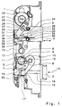
- FIG. 1 one is designated as a whole by 1 Lock housing shown, with the cover removed has been. Inside the case are a trap 2 and a Latch 3 can be moved in the direction of the double arrow 4. Furthermore is in the lock housing 1 a follower 5 in the sense of Double arrow 6 rotatably mounted. She owns one Breakthrough 7, in particular a square breakthrough, for Holds a square mandrel of a handle or one similar actuator. A radially protruding one Approach 8 of the follower 5 is below one Projection 9 of a latch arm 10, over which the latch 2 can be inferred.
- the trigger nut 5 has also a partial sprocket 11, which in a rack 12 engages, which via a not shown Return spring, which is in a spring housing 13 is in the rest position shown in Figure 1 is held. From this rest position, the rack 12 be shifted in both directions. So if you have the Handle nut 5 rotates in the direction of arrow 14, so this causes on the one hand a compression of the return spring, on the other hand, the approach 8 comes to rest on the projection 9 of the latch arm 10 and pivots this in the direction of Clockwise around a bearing 15. This will make a Actuating arm 16 moves and engages a shoulder 17 a trap tail 18. This causes the trap 2 in the direction of arrow 19 into the lock housing 1 is closed.
- Extending the trap 2 after releasing the trigger and after resetting the Handle nut 5 by the return spring, not shown is supported by a leg spring 20, which is supported on the one hand on the lock housing 1, on the other hand the shoulder 17 attacks and the trap 2 from the Slides out lock housing 1.
- the extension movement is about 10 mm.
- a rotary element 21 is rotatable in the lock housing 1 mounted, the rotary member 21 having a slot 22nd is provided.
- This slot 22 engages e.g. on the one side a corresponding wedge of a rotary knob and on the other side a corresponding wedge with one a key operated cylinder.
- Rotating element 21 formed such that it is already in existing recesses in which a profile cylinder can be used, can be installed.
- On the rotating element 21 is a first arm 23 of an articulated lever 24 around a bolt 25 pivotally attached.
- the first arm 23 an elongated hole 26 in which a housing-fixed pin 27th intervenes.
- At the opposite end of the bolt 25 is the first arm via a pivot bearing 28 with a second arm 29 pivotably coupled, the second arm 29 by means of a bolt 30 on a bolt tail 31 of the bolt 3 attacks.
- a leg spring 32 is around the bolt 30 stored, the one leg 33 in one Support 34 of the bolt 3 supports and with her other Leg 35 encompasses the pivot bearing 28.
- the leg spring 32 is designed so that the pivot bearing 28 in the direction is pushed clockwise around the bolt 30.
- the lock shown in Figure 1 has the main advantage that it a trap on the bottom, like American locks 2 and an overhead latch 3, the Bolt 3 by actuating the rotating element 21 by means of a Key or using a rotary knob in the direction of the Clockwise (in the position shown) from the Lock housing 1 can be pre-locked.
- the extension is about 25 mm.
- the locking of the bolt 3 by rotating the Rotating element 21 is carried out in the clockwise direction in that the first arm 23 when rotating the rotating member 21 carried by the bolt 25 and against the direction of Is rotated clockwise around the pin 27 and also is moved in the direction of the elongated hole 26.
- the pivot bearing 28 an arcuate movement, which is indicated by dashed line 36 is.
- the pivot bearing 28 has its on the viewer facing away from an axial projection, which in the 1 shown position of the articulated lever 24 a engages shoulder 37 fixed to the housing. That way prevents the bolt 3 without twisting the Rotating element 21 can be moved from the lock housing 1 can.
- In the end position of the Swivel bearing 28 is located with the bolt 3 excluded the axial projection of the pivot bearing 28 behind one second housing-fixed shoulder 38, which causes that the excluded bolt 3 without twisting the Rotating element 21 not in the lock housing 1 can be pushed back.
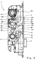
- FIG. 2 shows a second embodiment of the lock according to the invention, the same components with same reference numerals.
- this Embodiment is in the lock housing 1 Espagnolette plate 39 in the direction of double arrow 40 slidably mounted.
- This drive rod plate 39 are coupled at 41 and 42 drive rods 43.
- This Driving rods 43 are located behind face plates 44, which the lock housing 1 in the installed position on the Complete and cover the visible side.
- FIG. 2 there is a rotary slide 45 on the trigger nut 5 rotatably attached. If the follower 5 is actuated, then the rotary valve 45 is taken, which is still below is explained in more detail.
- the rotary valve 45 has one Bolt 46 on the in an elongated hole 47 in the Espagnolette plate 39 engages.
- the Rotary slide valve 45 has a curved slot 48, which makes it Camp 15 is bypassed.
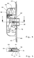
- FIG. 1 An additional lock 49 is shown in FIG from which the cover is also removed.
- This Additional lock 49 is on the drive rod 43 with the Lock housing 1 of the mortise lock connected.
- a latch bolt 50 in the direction of Double arrow 51 slidably mounted. That latchbolt 50 is in the view shown in its excluded position. The latch bolt 50 sits down backwards in a trap tail 52 that one Has projection 53.
- a latch lock lever 55 is pivotally mounted and over a locking lever spring 56, which is designed as a leg spring is spring-loaded in the clockwise direction.
- the latch bolt 50 is in the complete extended position, i.e. in the latch position, then a catch blocking edge 57 engages behind the projection 53 can between the projection 53 and Trap locking edge 57, as shown in Figure 3, a there is a short distance, but the Latch locking edge 57 in the displacement path of the projection 53, so that the latch bolt 50 does not easily get into that Housing of the additional lock 49 can be inserted.
- the latch bolt 50 is therefore in his Locking position against unauthorized insertion locked.
- a trap reset lever 58 the one with his arm 59 at the free end of the drive rod 43 and with his other arm 60 on another Projection 61 of the tail 52 rests, pivoted, then a nose 62 of the free arm 60 engages one Link 63 of latch lock lever 55 and lifts it out its locking position, in which the Trap locking edge 57 engages behind the projection 53 so far from that the trap locking edge 57 from the displacement of the Projection 53 emerges.
- the arm 60 is on Projection 61 and pulls when pivoting the Case return lever 58 the latch bolt 50 in the Additional lock 49. Extending the latch bolt 50 takes place via a latch extension lever 64, which at 65 is supported and countered by a trap extension spring 66 clockwise around the bearing 65 becomes.
- the latch extension lever 64 engages with its free End on latchbolt 50 and try this out of Extend additional lock 49.
- FIG. 4 shows a second embodiment of the Additional lock 49 shown.
- the latch bolt 50 is automatically removed from the lock housing extended when the door is closed.
- the latch bolt 50 with one in its longitudinal direction provided groove 70 open on one side.
- this Groove 70 is a locking element 71, which by a Adapter sleeve 72 pivotable in the groove 70 and thus in Latch bolt 50 is mounted.
- This locking element 71 is with a locking lug 73 and a trigger lug 74 Mistake.
- the drive rod plate 39 can with her Cutout 79 only between the blocking extension 75 (77) and a guide block 80, which is fixed to the housing, be relocated. However, the drive rod plate 39 no longer back, i.e. be moved up. A Opening the lock with a key locked bolt 3 can not by pressing the Handle nut 5 must be opened.
- a bar exclusion 81 is shown in FIGS. 6 and 7 shown, which is not connected to a clutch 82 driving rod 43 shown is coupled.
- This Coupling 82 is located on a first rack 83, which in the housing 84 of the rod exclusion 81 flows into.
- This first rack 83 drives two gears 85 on, which is mounted on the bearing journal 86 are.
- a second rack 87 driven is now opposite to the first Rack 83 moves. Via the gears 85 a change of direction.
- This second rack 87 transmits the movement on two gear pairs 88, which on Bearing journals 89 are stored. These gear pairs will be 88 from the second rack 87 on its smaller gear 90 driven.
- the rack 87 with a Rack part 91 provided which is much narrower is designed as the rack 87, but a larger one Has thickness, which can be seen from Figure 6.
- a third one next to the rack part 91 Rack 92 which has a smaller thickness and with the larger gear 93 of the gear pair 88 meshes.
- the Rack part 91 and the third rack 92 form with the gear pair 88 a transmission gear, so that Displacement movement of the drive rod 43 an exclusion a locking pin 94 of about 25 mm.
- This locking pin 94 is a hook connection 95 connected to the third rack 92, the lower end of the locking pin 94 via a Compression spring 96 is loaded in the direction of exclusion.
- the locking pin 94 can be completed Exclusion from the third rack extending further 92 are uncoupled, so that damage to the Transmission gear or the rod exclusion 81 generally avoided.
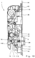
- FIG 8 shows a further variant of the invention Mortise lock, in which the drive rod plate 39 with a backdrop 97 is provided.
- this backdrop 97 which by an inclined section 98 and an in Section 99 extending in the direction of the double arrow 40 and an end section 100 orthogonal thereto , a guide pin 101 engages, which on one Bar extension 102 protrudes. If the bolt 3 by means of Rotary element 21, i.e. by means of a key or the Turned the knob, which is described above, then the guide pin 101 is moved in the backdrop 97. At the Excluding the bolt 3, the guide pin 101 in Shifted in the direction of arrow 103.
- FIG. 9 shows a further variant of the shown lock according to the invention, in which the Exclusion of the bolt 3 by pressing the follower 5 in the clockwise direction.
- a thing Lock is also known as a "Fastlock" lock.
- the drive rod plate 39 a backdrop 104, which has an inclined section 98 however, one in the direction of movement of the drive rod plate 39 extending end portion 105.
- the guide pin 101 is guided.
- the Turn follower 5 clockwise then is on the rotary valve 45 of the bolt 46, which in a Elongated hole 47 of the drive rod plate 39 engages downward emotional.
- this bolt can also be excluded by that the rotating member 21 is rotated so that the ring gear 106 via the pinion 107 with the rack 108 of the Bar tail 31 combs, and in this way the bar 3rd is excluded.
- bolt 3 is pushed out, however definitely the rack 108, which is correspondingly short out of engagement with the pinion 107.
- the drive rod plate 39 by twisting the Press follower 5 counterclockwise above, i.e. to move in the opening direction, so this movement through the shoulder 38 fixed to the housing blocked, on the axial projection of the pivot bearing 28 strikes.
- the bolt can therefore not over the pusher, or can be pushed back via the follower 5.
- a Unlocking can only be done via the rotating element 21, i.e.
- the rotating element 21 is included provided with a riddle, formed by two disks will, which on their mutually facing end faces Saw teeth are equipped.
- the saw teeth are like this ordered that they are permanently in one direction Are engaged, and in the other direction of rotation from one certain torque disengage.
- FIG. 10 shows a further embodiment of the shown lock according to the invention, in which the trap 2 the latch bolt 50 shown in FIGS. 4 and 5 is shown, has the corresponding structure. Will one Door closed with such a lock 1, then the lock of the locking element 109 is automatically released and the trap 2 is driven by the force of a compression spring 110 which acts on the trap tail 18 excluded.
- the trap tail 18 has a nose 111 that engages a locking lever 112 which by one Bolt 113 fixed to the housing is pivotable.
- This Locking lever 112 engages behind the free end 114 of the Espagnolette plate 39 and blocks it against one Shift down in which direction the Espagnolette plate 39 loaded by a compression spring 115 is. However, the locking lever 112 around the pin 113 in Pivoted clockwise over the nose 112, then the backhand is released and the Espagnolette plate 39 can be moved downwards.
- the lock according to the invention has the essential advantage that it has a variety of conventional components and can still be used for the US market.
Landscapes
- Engineering & Computer Science (AREA)
- Mechanical Engineering (AREA)
- Structural Engineering (AREA)
- Lock And Its Accessories (AREA)
- Hinges (AREA)
Applications Claiming Priority (2)
| Application Number | Priority Date | Filing Date | Title |
|---|---|---|---|
| DE29719611U | 1997-11-05 | ||
| DE29719611U DE29719611U1 (de) | 1997-11-05 | 1997-11-05 | Schloß, insbesondere Einsteckschloß für eine Außentür |
Publications (3)
| Publication Number | Publication Date |
|---|---|
| EP0915221A2 true EP0915221A2 (fr) | 1999-05-12 |
| EP0915221A3 EP0915221A3 (fr) | 2001-06-06 |
| EP0915221B1 EP0915221B1 (fr) | 2003-07-30 |
Family
ID=8048183
Family Applications (1)
| Application Number | Title | Priority Date | Filing Date |
|---|---|---|---|
| EP98105694A Expired - Lifetime EP0915221B1 (fr) | 1997-11-05 | 1998-03-28 | Serrure, notamment une serrure encastrée pour une porte extérieure |
Country Status (5)
| Country | Link |
|---|---|
| US (1) | US6266981B1 (fr) |
| EP (1) | EP0915221B1 (fr) |
| CA (1) | CA2248770C (fr) |
| DE (2) | DE29719611U1 (fr) |
| DK (1) | DK0915221T3 (fr) |
Cited By (1)
| Publication number | Priority date | Publication date | Assignee | Title |
|---|---|---|---|---|
| FR2953245A1 (fr) * | 2009-12-01 | 2011-06-03 | Map Massard | Entrebailleur pour un ouvrant muni d'une tringle de cremone |
Families Citing this family (42)
| Publication number | Priority date | Publication date | Assignee | Title |
|---|---|---|---|---|
| DE10032647A1 (de) * | 2000-07-05 | 2002-01-17 | Winkhaus Fa August | Einsteckschloss |
| ES2213420B1 (es) * | 2001-05-23 | 2005-05-01 | Talleres De Escoriaza, S.A. | Dispositivo impulsor de la salida del pestillo en cerraduras. |
| AUPR604601A0 (en) * | 2001-06-29 | 2001-07-26 | Gainsborough Hardware Industries Limited | A mortice lock |
| DE10209575B4 (de) * | 2002-02-27 | 2014-11-27 | Carl Fuhr Gmbh & Co. Kg | Standflügelverschluss |
| DE10343230A1 (de) * | 2002-09-17 | 2004-09-23 | Southco, Inc. | Zweifach wirkendes Ladeflächen-Schnappschloß |
| US6733050B1 (en) * | 2002-11-12 | 2004-05-11 | Shyang Feng Electric & Machinery Co., Ltd. | Bolt dock for door lock |
| SG110175A1 (en) * | 2003-09-22 | 2005-04-28 | Lockwood Security Products Pty | A multipoint lock |
| DE10354184A1 (de) | 2003-11-20 | 2005-06-23 | Aug. Winkhaus Gmbh & Co. Kg | Treibstangenbeschlag |
| US20060123859A1 (en) * | 2004-12-13 | 2006-06-15 | Gonzalez Fermin G | Mortise lock with automatic projection of dead bolt |
| EP1672153B1 (fr) | 2004-12-18 | 2013-12-11 | Roto Frank Ag | Serrure avec pêne dormant et dispositif de commande du pêne dormant |
| US7363784B2 (en) * | 2005-02-28 | 2008-04-29 | Assa Abloy, Inc. | Independently interactive interconnected lock |
| WO2008153707A2 (fr) | 2007-05-21 | 2008-12-18 | Truth Hardware Corporation | Mécanisme de verrouillage multipoint |
| TWM338889U (en) * | 2007-12-17 | 2008-08-21 | Imp Hardware Taiwan Ltd | Door lock using key to drive transmission mechanism |
| TWM338888U (en) * | 2007-12-17 | 2008-08-21 | Imp Hardware Taiwan Ltd | Door lock having transmission mechanism |
| US7661279B2 (en) * | 2008-01-23 | 2010-02-16 | Door & Window Hardware Co. | Lock assembly |
| US8899635B2 (en) | 2008-10-03 | 2014-12-02 | Truth Hardware Corporation | Sliding door multipoint mortise lock with shoot bolts |
| US8348308B2 (en) | 2008-12-19 | 2013-01-08 | Amesbury Group, Inc. | High security lock for door |
| US9222286B2 (en) | 2009-03-20 | 2015-12-29 | Hanchett Entry Systems, Inc. | Multiple point door locking system |
| US8550506B2 (en) | 2009-06-30 | 2013-10-08 | Truth Hardware Corporation | Multi-point mortise lock mechanism for swinging door |
| US8939474B2 (en) | 2011-06-03 | 2015-01-27 | Amesbury Group, Inc. | Lock with sliding locking elements |
| US9428937B2 (en) * | 2011-07-22 | 2016-08-30 | Amesbury Group, Inc. | Multi-point lock having sequentially-actuated locking elements |
| KR101301247B1 (ko) * | 2012-04-20 | 2013-08-28 | 삼성에스엔에스 주식회사 | 양방향 해정이 가능한 모티스 구조 |
| US9765550B2 (en) | 2012-08-31 | 2017-09-19 | Amesbury Group, Inc. | Passive door lock mechanisms |
| DE102012108242A1 (de) * | 2012-09-05 | 2014-03-06 | Dorma Gmbh + Co. Kg | Schloss für eine Tür |
| US8875549B2 (en) | 2012-10-24 | 2014-11-04 | Door & Window Hardware Co. | Lock assembly |
| US9637957B2 (en) | 2012-11-06 | 2017-05-02 | Amesbury Group, Inc. | Automatically-extending remote door lock bolts |
| EP2752538B1 (fr) * | 2013-01-04 | 2016-11-23 | BKS GmbH | Dispositif de verrouillage |
| AT515799B1 (de) * | 2014-03-31 | 2015-12-15 | Roto Frank Ag | Schloss |
| AU2015203396A1 (en) | 2014-06-20 | 2016-01-21 | Truth Hardware Corporation | Recessed lock actuating device for sliding doors |
| TWI544129B (zh) * | 2014-08-26 | 2016-08-01 | 台灣福興工業股份有限公司 | 鎖具結構 |
| US9790716B2 (en) | 2014-10-16 | 2017-10-17 | Amesbury Group, Inc. | Opposed hook sliding door lock |
| EP3115530B1 (fr) * | 2015-07-07 | 2018-05-16 | KALE Kilit ve Kalip Sanayi A.S. | Serrure pour une porte intérieure |
| US10968661B2 (en) | 2016-08-17 | 2021-04-06 | Amesbury Group, Inc. | Locking system having an electronic deadbolt |
| US11111698B2 (en) | 2016-12-05 | 2021-09-07 | Endura Products, Llc | Multipoint lock |
| US10876324B2 (en) | 2017-01-19 | 2020-12-29 | Endura Products, Llc | Multipoint lock |
| CN110546340A (zh) | 2017-04-18 | 2019-12-06 | 埃美斯博瑞集团有限公司 | 模块化电子锁闩系统 |
| US10808424B2 (en) | 2017-05-01 | 2020-10-20 | Amesbury Group, Inc. | Modular multi-point lock |
| US11066850B2 (en) | 2017-07-25 | 2021-07-20 | Amesbury Group, Inc | Access handle for sliding doors |
| CA3036398A1 (fr) | 2018-03-12 | 2019-09-12 | Amesbury Group, Inc. | Systemes de pene dormant electronique |
| US11834866B2 (en) | 2018-11-06 | 2023-12-05 | Amesbury Group, Inc. | Flexible coupling for electronic deadbolt systems |
| US11661771B2 (en) | 2018-11-13 | 2023-05-30 | Amesbury Group, Inc. | Electronic drive for door locks |
| US11746565B2 (en) | 2019-05-01 | 2023-09-05 | Endura Products, Llc | Multipoint lock assembly for a swinging door panel |
Citations (1)
| Publication number | Priority date | Publication date | Assignee | Title |
|---|---|---|---|---|
| DE9208526U1 (de) | 1992-06-25 | 1992-09-10 | Gretsch-Unitas GmbH Baubeschläge, 7257 Ditzingen | Schloß, insbesondere Einsteckschloß für eine Außentür |
Family Cites Families (12)
| Publication number | Priority date | Publication date | Assignee | Title |
|---|---|---|---|---|
| US1290439A (en) * | 1916-11-11 | 1919-01-07 | Sargent & Co | Lock. |
| US4011741A (en) * | 1976-04-06 | 1977-03-15 | Tre Corporation | Lock cylinder with dual drivers |
| US4578967A (en) * | 1982-04-22 | 1986-04-01 | Yu Jer M | Combined door latch and deadbolt arrangement |
| AU569735B2 (en) * | 1983-05-04 | 1988-02-18 | Ogden Industries Pty Ltd | Lock |
| DE3863642D1 (de) * | 1987-09-04 | 1991-08-14 | Theodor Krachten | Schloss mit schlossfalle und sperriegel sowie mit einem die schlossfalle verriegelnden sperrschlitten. |
| US4870841A (en) * | 1988-10-06 | 1989-10-03 | Yale Security Inc. | Lock deadbolt protector |
| DE4118480A1 (de) * | 1991-06-05 | 1992-12-10 | Fuhr Carl Gmbh & Co | Schloss, insbesondere einsteckschloss |
| DE9112079U1 (de) * | 1991-09-27 | 1993-01-28 | Siegenia-Frank Kg, 5900 Siegen | Betätigungsgetriebe für längsverschiebbare Treibstangen an Beschlägen von Fenstern und Türen o.dgl. |
| ATE181132T1 (de) * | 1994-11-17 | 1999-06-15 | Fliether Karl Gmbh & Co | Schloss, insbesondere treibstangenschloss mit zweigeteilter drückernuss |
| DE29608862U1 (de) * | 1996-05-17 | 1997-09-18 | Gretsch-Unitas GmbH Baubeschläge, 71254 Ditzingen | Schloß, insbesondere Einsteckschloß |
| US5813255A (en) * | 1996-09-25 | 1998-09-29 | Pdq Industries, Inc. | Lock mechanism with closed case changeovers |
| US5819562A (en) * | 1997-05-19 | 1998-10-13 | Christ; Willy | Door lock having multiple locking bolts |
-
1997
- 1997-11-05 DE DE29719611U patent/DE29719611U1/de not_active Expired - Lifetime
-
1998
- 1998-03-28 DE DE59809147T patent/DE59809147D1/de not_active Expired - Fee Related
- 1998-03-28 DK DK98105694T patent/DK0915221T3/da active
- 1998-03-28 EP EP98105694A patent/EP0915221B1/fr not_active Expired - Lifetime
- 1998-05-06 US US09/073,193 patent/US6266981B1/en not_active Expired - Lifetime
- 1998-09-29 CA CA002248770A patent/CA2248770C/fr not_active Expired - Fee Related
Patent Citations (1)
| Publication number | Priority date | Publication date | Assignee | Title |
|---|---|---|---|---|
| DE9208526U1 (de) | 1992-06-25 | 1992-09-10 | Gretsch-Unitas GmbH Baubeschläge, 7257 Ditzingen | Schloß, insbesondere Einsteckschloß für eine Außentür |
Cited By (1)
| Publication number | Priority date | Publication date | Assignee | Title |
|---|---|---|---|---|
| FR2953245A1 (fr) * | 2009-12-01 | 2011-06-03 | Map Massard | Entrebailleur pour un ouvrant muni d'une tringle de cremone |
Also Published As
| Publication number | Publication date |
|---|---|
| DE59809147D1 (de) | 2003-09-04 |
| EP0915221B1 (fr) | 2003-07-30 |
| CA2248770A1 (fr) | 1999-05-05 |
| CA2248770C (fr) | 2005-04-12 |
| DE29719611U1 (de) | 1999-03-11 |
| EP0915221A3 (fr) | 2001-06-06 |
| DK0915221T3 (da) | 2003-11-24 |
| US6266981B1 (en) | 2001-07-31 |
Similar Documents
| Publication | Publication Date | Title |
|---|---|---|
| EP0915221B1 (fr) | Serrure, notamment une serrure encastrée pour une porte extérieure | |
| DE2611359C2 (de) | Treibstangenverschluß für Türflügel | |
| EP1932989B1 (fr) | Système de fermeture pour portes, fenêtres ou analogues, en particulier crémone-serrure à fonction d'urgence et de verrouillage à plusieurs points | |
| DE3447748C2 (fr) | ||
| EP0911470B1 (fr) | Dispositif de verrouillage | |
| DE4324300C2 (de) | Antipanik-Türschloß | |
| DE2914372C2 (de) | Von außen aufschließbares Fallen-Schubriegel-Panikschloß | |
| EP0798436A2 (fr) | Dispositif de verrouillage | |
| DE102007035116A1 (de) | Gelenkstabschloss | |
| EP2264268B2 (fr) | Crémone serrure | |
| DE3144663A1 (de) | Tuerverschluss | |
| DE3836693A1 (de) | Treibstangenschloss | |
| DE3503466C2 (fr) | ||
| DE19813166A1 (de) | Türschloßanordnung, vorzugsweise Treibstangenschloßanordnung | |
| DE4114007C2 (de) | Treibstangenverschluß | |
| DE102015000606A1 (de) | Verriegelungsvorrichtung für einen schwenkbar gelagerten Flügel | |
| EP3805493A2 (fr) | Serrure modulaire à fonction anti-panique | |
| DE3034764C2 (de) | Betätigungsvorrichtung für Treibstangenbeschläge | |
| DE3931101A1 (de) | Automatisch verriegelndes schloss | |
| EP0298292B1 (fr) | Serrure de porte à pêne et demi-tour coulissants | |
| DE19628011C5 (de) | Spereinrichtung für die Riegel eine Riegelwerks | |
| DE29909660U1 (de) | Türverschluß | |
| DE868122C (de) | Fallenschloss mit Sperreinrichtung | |
| EP1347130A1 (fr) | Serrure pour portes de sécurité | |
| EP0990758A2 (fr) | Serrure additionelle pour crémone |
Legal Events
| Date | Code | Title | Description |
|---|---|---|---|
| PUAI | Public reference made under article 153(3) epc to a published international application that has entered the european phase |
Free format text: ORIGINAL CODE: 0009012 |
|
| AK | Designated contracting states |
Kind code of ref document: A2 Designated state(s): DE DK FR GB SE |
|
| AX | Request for extension of the european patent |
Free format text: AL;LT;LV;MK;RO;SI |
|
| PUAL | Search report despatched |
Free format text: ORIGINAL CODE: 0009013 |
|
| AK | Designated contracting states |
Kind code of ref document: A3 Designated state(s): AT BE CH DE DK ES FI FR GB GR IE IT LI LU MC NL PT SE |
|
| AX | Request for extension of the european patent |
Free format text: AL;LT;LV;MK;RO;SI |
|
| 17P | Request for examination filed |
Effective date: 20010531 |
|
| AKX | Designation fees paid |
Free format text: DE DK FR GB SE |
|
| GRAH | Despatch of communication of intention to grant a patent |
Free format text: ORIGINAL CODE: EPIDOS IGRA |
|
| GRAH | Despatch of communication of intention to grant a patent |
Free format text: ORIGINAL CODE: EPIDOS IGRA |
|
| GRAA | (expected) grant |
Free format text: ORIGINAL CODE: 0009210 |
|
| AK | Designated contracting states |
Designated state(s): DE DK FR GB SE |
|
| REG | Reference to a national code |
Ref country code: GB Ref legal event code: FG4D Free format text: NOT ENGLISH |
|
| GBT | Gb: translation of ep patent filed (gb section 77(6)(a)/1977) |
Effective date: 20030730 |
|
| REF | Corresponds to: |
Ref document number: 59809147 Country of ref document: DE Date of ref document: 20030904 Kind code of ref document: P |
|
| REG | Reference to a national code |
Ref country code: SE Ref legal event code: TRGR |
|
| REG | Reference to a national code |
Ref country code: DK Ref legal event code: T3 |
|
| PGFP | Annual fee paid to national office [announced via postgrant information from national office to epo] |
Ref country code: DK Payment date: 20040123 Year of fee payment: 7 |
|
| PGFP | Annual fee paid to national office [announced via postgrant information from national office to epo] |
Ref country code: SE Payment date: 20040302 Year of fee payment: 7 |
|
| PGFP | Annual fee paid to national office [announced via postgrant information from national office to epo] |
Ref country code: GB Payment date: 20040303 Year of fee payment: 7 |
|
| PGFP | Annual fee paid to national office [announced via postgrant information from national office to epo] |
Ref country code: DE Payment date: 20040305 Year of fee payment: 7 |
|
| PGFP | Annual fee paid to national office [announced via postgrant information from national office to epo] |
Ref country code: FR Payment date: 20040310 Year of fee payment: 7 |
|
| ET | Fr: translation filed | ||
| PLBE | No opposition filed within time limit |
Free format text: ORIGINAL CODE: 0009261 |
|
| STAA | Information on the status of an ep patent application or granted ep patent |
Free format text: STATUS: NO OPPOSITION FILED WITHIN TIME LIMIT |
|
| 26N | No opposition filed |
Effective date: 20040504 |
|
| PG25 | Lapsed in a contracting state [announced via postgrant information from national office to epo] |
Ref country code: GB Free format text: LAPSE BECAUSE OF NON-PAYMENT OF DUE FEES Effective date: 20050328 |
|
| PG25 | Lapsed in a contracting state [announced via postgrant information from national office to epo] |
Ref country code: SE Free format text: LAPSE BECAUSE OF NON-PAYMENT OF DUE FEES Effective date: 20050329 |
|
| PG25 | Lapsed in a contracting state [announced via postgrant information from national office to epo] |
Ref country code: DK Free format text: LAPSE BECAUSE OF NON-PAYMENT OF DUE FEES Effective date: 20050331 |
|
| PG25 | Lapsed in a contracting state [announced via postgrant information from national office to epo] |
Ref country code: DE Free format text: LAPSE BECAUSE OF NON-PAYMENT OF DUE FEES Effective date: 20051001 |
|
| EUG | Se: european patent has lapsed | ||
| GBPC | Gb: european patent ceased through non-payment of renewal fee |
Effective date: 20050328 |
|
| PG25 | Lapsed in a contracting state [announced via postgrant information from national office to epo] |
Ref country code: FR Free format text: LAPSE BECAUSE OF NON-PAYMENT OF DUE FEES Effective date: 20051130 |
|
| REG | Reference to a national code |
Ref country code: DK Ref legal event code: EBP |
|
| REG | Reference to a national code |
Ref country code: FR Ref legal event code: ST Effective date: 20051130 |