US8939474B2 - Lock with sliding locking elements - Google Patents
Lock with sliding locking elements Download PDFInfo
- Publication number
- US8939474B2 US8939474B2 US13/152,913 US201113152913A US8939474B2 US 8939474 B2 US8939474 B2 US 8939474B2 US 201113152913 A US201113152913 A US 201113152913A US 8939474 B2 US8939474 B2 US 8939474B2
- Authority
- US
- United States
- Prior art keywords
- lock
- housing
- locking element
- locking
- slide mechanism
- Prior art date
- Legal status (The legal status is an assumption and is not a legal conclusion. Google has not performed a legal analysis and makes no representation as to the accuracy of the status listed.)
- Active, expires
Links
- 238000005516 engineering process Methods 0.000 description 10
- 238000000034 method Methods 0.000 description 10
- 238000004519 manufacturing process Methods 0.000 description 4
- 230000004048 modification Effects 0.000 description 3
- 238000012986 modification Methods 0.000 description 3
- 238000000926 separation method Methods 0.000 description 3
- 239000011521 glass Substances 0.000 description 2
- 229910001369 Brass Inorganic materials 0.000 description 1
- HCHKCACWOHOZIP-UHFFFAOYSA-N Zinc Chemical compound [Zn] HCHKCACWOHOZIP-UHFFFAOYSA-N 0.000 description 1
- 239000000853 adhesive Substances 0.000 description 1
- 230000001070 adhesive effect Effects 0.000 description 1
- 239000010951 brass Substances 0.000 description 1
- 238000010276 construction Methods 0.000 description 1
- 238000002347 injection Methods 0.000 description 1
- 239000007924 injection Substances 0.000 description 1
- 238000009434 installation Methods 0.000 description 1
- 239000000463 material Substances 0.000 description 1
- 239000002184 metal Substances 0.000 description 1
- 229910052751 metal Inorganic materials 0.000 description 1
- 150000002739 metals Chemical class 0.000 description 1
- 238000000908 micropen lithography Methods 0.000 description 1
- 239000002991 molded plastic Substances 0.000 description 1
- 239000004033 plastic Substances 0.000 description 1
- 229920003023 plastic Polymers 0.000 description 1
- 238000009420 retrofitting Methods 0.000 description 1
- 229910001220 stainless steel Inorganic materials 0.000 description 1
- 239000010935 stainless steel Substances 0.000 description 1
- 239000000126 substance Substances 0.000 description 1
- 229910052725 zinc Inorganic materials 0.000 description 1
- 239000011701 zinc Substances 0.000 description 1
Images


Classifications
-
- E—FIXED CONSTRUCTIONS
- E05—LOCKS; KEYS; WINDOW OR DOOR FITTINGS; SAFES
- E05B—LOCKS; ACCESSORIES THEREFOR; HANDCUFFS
- E05B63/00—Locks or fastenings with special structural characteristics
- E05B63/14—Arrangement of several locks or locks with several bolts, e.g. arranged one behind the other
-
- E—FIXED CONSTRUCTIONS
- E05—LOCKS; KEYS; WINDOW OR DOOR FITTINGS; SAFES
- E05B—LOCKS; ACCESSORIES THEREFOR; HANDCUFFS
- E05B65/00—Locks or fastenings for special use
- E05B65/08—Locks or fastenings for special use for sliding wings
- E05B65/087—Locks or fastenings for special use for sliding wings the bolts sliding parallel to the wings
-
- E—FIXED CONSTRUCTIONS
- E05—LOCKS; KEYS; WINDOW OR DOOR FITTINGS; SAFES
- E05B—LOCKS; ACCESSORIES THEREFOR; HANDCUFFS
- E05B17/00—Accessories in connection with locks
- E05B2017/0095—Means preventing wrong operation, e.g. preventing damaging contact between extended bolt and striker or bolt and frame
-
- E—FIXED CONSTRUCTIONS
- E05—LOCKS; KEYS; WINDOW OR DOOR FITTINGS; SAFES
- E05B—LOCKS; ACCESSORIES THEREFOR; HANDCUFFS
- E05B65/00—Locks or fastenings for special use
- E05B65/0025—Locks or fastenings for special use for glass wings
-
- E—FIXED CONSTRUCTIONS
- E05—LOCKS; KEYS; WINDOW OR DOOR FITTINGS; SAFES
- E05B—LOCKS; ACCESSORIES THEREFOR; HANDCUFFS
- E05B65/00—Locks or fastenings for special use
- E05B65/02—Locks or fastenings for special use for thin, hollow, or thin-metal wings
- E05B65/025—Locks or fastenings for special use for thin, hollow, or thin-metal wings for lockers
-
- Y—GENERAL TAGGING OF NEW TECHNOLOGICAL DEVELOPMENTS; GENERAL TAGGING OF CROSS-SECTIONAL TECHNOLOGIES SPANNING OVER SEVERAL SECTIONS OF THE IPC; TECHNICAL SUBJECTS COVERED BY FORMER USPC CROSS-REFERENCE ART COLLECTIONS [XRACs] AND DIGESTS
- Y10—TECHNICAL SUBJECTS COVERED BY FORMER USPC
- Y10S—TECHNICAL SUBJECTS COVERED BY FORMER USPC CROSS-REFERENCE ART COLLECTIONS [XRACs] AND DIGESTS
- Y10S292/00—Closure fasteners
- Y10S292/46—Sliding door fasteners
-
- Y—GENERAL TAGGING OF NEW TECHNOLOGICAL DEVELOPMENTS; GENERAL TAGGING OF CROSS-SECTIONAL TECHNOLOGIES SPANNING OVER SEVERAL SECTIONS OF THE IPC; TECHNICAL SUBJECTS COVERED BY FORMER USPC CROSS-REFERENCE ART COLLECTIONS [XRACs] AND DIGESTS
- Y10—TECHNICAL SUBJECTS COVERED BY FORMER USPC
- Y10T—TECHNICAL SUBJECTS COVERED BY FORMER US CLASSIFICATION
- Y10T29/00—Metal working
- Y10T29/49—Method of mechanical manufacture
- Y10T29/49718—Repairing
- Y10T29/49721—Repairing with disassembling
- Y10T29/4973—Replacing of defective part
-
- Y—GENERAL TAGGING OF NEW TECHNOLOGICAL DEVELOPMENTS; GENERAL TAGGING OF CROSS-SECTIONAL TECHNOLOGIES SPANNING OVER SEVERAL SECTIONS OF THE IPC; TECHNICAL SUBJECTS COVERED BY FORMER USPC CROSS-REFERENCE ART COLLECTIONS [XRACs] AND DIGESTS
- Y10—TECHNICAL SUBJECTS COVERED BY FORMER USPC
- Y10T—TECHNICAL SUBJECTS COVERED BY FORMER US CLASSIFICATION
- Y10T292/00—Closure fasteners
- Y10T292/08—Bolts
- Y10T292/096—Sliding
- Y10T292/0969—Spring projected
-
- Y—GENERAL TAGGING OF NEW TECHNOLOGICAL DEVELOPMENTS; GENERAL TAGGING OF CROSS-SECTIONAL TECHNOLOGIES SPANNING OVER SEVERAL SECTIONS OF THE IPC; TECHNICAL SUBJECTS COVERED BY FORMER USPC CROSS-REFERENCE ART COLLECTIONS [XRACs] AND DIGESTS
- Y10—TECHNICAL SUBJECTS COVERED BY FORMER USPC
- Y10T—TECHNICAL SUBJECTS COVERED BY FORMER US CLASSIFICATION
- Y10T292/00—Closure fasteners
- Y10T292/08—Bolts
- Y10T292/096—Sliding
- Y10T292/1014—Operating means
- Y10T292/1016—Cam
Definitions
- the most commonly used mortise lock is the single-point lock.
- a single locking element e.g., a hook
- manufacture of single hook locks is generally cost effective.
- Single-point locks suffer the drawback, however, of being somewhat easily broken or disengaged by a fairly insignificant force, thus defeating the purpose for which the lock is intended.
- Multi-point locks include two or more locking elements that pivot out of one or more lock housings to engage with keeper elements on a door frame. Multi-point locks offer increased security over single-point locks that include only a single locking element. While more secure, multi-point locks are typically larger than single-point locks and more expensive to manufacture, due to the increased number of complex components utilized in the lock mechanism. Also, most sliding door manufacturers only provide an opening in the door for the smaller, single-point mortise locks.
- the technology relates to a lock having: a housing; a slide mechanism adapted to translate in the housing along a locking axis; and a locking element connected to the slide mechanism, the locking element adapted to translate along the locking axis with the slide mechanism.
- the locking element is deflectably connected to the slide mechanism, such that a force applied to the locking element substantially orthogonal to the locking axis deflects the locking element into the housing.
- the locking element is biased outward from the housing.
- the locking element is at least two locking elements.
- the lock includes: a cam rotatably mounted relative to the housing; and a linkage fixed to the cam and slidably engaged with the slide mechanism, wherein rotation of the cam moves the slide mechanism from a first position to a second position.
- the slide mechanism includes a slot and the linkage includes a pin slidably engaged with the slot.
- the lock includes a spring for biasing the sliding mechanism in both the first position and the second position.
- the housing defines at least one slot, wherein the slot is substantially parallel to the locking axis.
- the sliding mechanism is slidably engaged with the slot.
- the locking element includes a head, wherein a distance from the head to the housing is adjustable.
- the lock includes an adjustment element for adjusting the distance from the head to the housing.
- the technology in another aspect, relates to a lock including: a housing; a locking element adapted to extend from the housing; and a lock mechanism for moving the locking element from a first position to a second position, wherein the locking element at least partially deflects into the housing upon application of a force to the locking element.
- the lock includes a spring to bias the locking element outward from the housing.
- the lock when in the first position and the second position, the locking element projects a predetermined distance from the housing.
- the lock includes at least one adjustment element for adjusting the predetermined distance.
- the technology in another aspect, relates to a method of locking a frame having a keeper to a door having a lock including a housing, a first locking element projecting from the housing, and an actuator for moving the first locking element from an unlocked position to a locked position, the method including the steps of: placing a locking edge of the door in contact with a locking edge of the frame, such that the first locking element extends into a first opening defined by the keeper; and actuating the actuator so as to move the first locking element from the unlocked position to the locked position.
- the placing step includes placing a second locking member into a second opening defined by the keeper.
- the first locking member and the second locking member are separated by a first distance in both the unlocked position and the locked position.
- the technology in another aspect, relates to a method of retrofitting a multi-point lock into a door panel, the method including the steps of: removing an existing lock from an opening defined by the door panel; and inserting the multi-point lock into the opening defined by the door panel, wherein the multi-point lock includes: a housing; a slide mechanism adapted to translate in the housing along a locking axis; and a plurality of locking elements connected to the slide mechanism, the locking elements adapted to translate along the locking axis with the slide mechanism.
- FIG. 1 is a perspective view of a multi-point lock.
- FIG. 2 is an exploded perspective view of a multi-point lock.
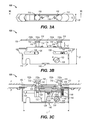
- FIG. 3A-3C are top, side and section views, respectively, of a multi-point lock in an unlocked position.
- FIGS. 4A-4C are top, side and section views, respectively, of a multi-point lock in a locked position.
- FIGS. 5A-5C are top, side and section views, respectively, of a multi-point lock in an anti-slam position.
- FIG. 6 depicts a method of locking a door to a frame with a lock.
- FIGS. 1 and 2 depict one embodiment of a multi-point lock (MPL) 100 .
- MPL multi-point lock
- a typical application for the locks depicted and described herein is for securing sliding glass doors.
- the multi-point locks depicted herein may be used for patio, entry, locker, or other doors, as well as sliding windows. Regardless, for clarity, a sliding door lock application will be described below.
- the multi-point locks depicted herein may also be ganged together to form multiple-assembly locks, such as those depicted in U.S. Provisional Patent Application No. 61/422,867, filed Dec. 28, 2010, entitled “System and Method for Ganging Locks,” the disclosure of which is hereby incorporated by reference herein in its entirety.
- the MPL 100 includes a housing 102 that includes an inner housing portion 102 a and an outer housing portion 102 b .
- the terms “inner” and “outer” refer to the side of the housing 102 that faces the inner or outer side of a door, and should not be considered limiting. Depending on the orientation of the MPL 100 , either side of the housing 102 may face either side of the door in which it is installed.
- the inner housing portion 102 a and the outer housing portion 102 b are joined at one or more swaging points 104 , although other devices, such as bolts, screws, chemical adhesives, etc., or combinations thereof, may be used to join the portions 102 a , 102 b .
- each of the portions 102 a , 102 b defines one or more projection slots 106 that are oriented substantially parallel to a locking axis A.
- the housing 102 also contains an actuation cam 108 that defines a slot 110 for receiving a tailpiece from a thumbturn or a key cylinder.
- One or both portions 102 a , 102 b of the housing 102 may partially or completely define one or more additional openings 112 .
- One or more locking elements 114 project from the housing 102 , generally in a direction that is substantially orthogonal to the locking axis A.
- the locking elements 114 include a shaft 116 and an enlarged head 118 , but other configurations are also contemplated.
- the head may be a curved or angular hook, coil, or other configuration that will secure the locking element 114 in a keeper when a door utilizing the MPL 100 is in a locked position.
- the shaft 116 of each locking element 114 is inserted into a bore 120 (see, e.g., FIG.
- a hardened locking element pin 124 prevents the locking element 114 from being pulled from the bore 120 . Additionally, the locking element pin 124 helps control a projection distance d of the head 118 , as described in more detail with regard to FIGS. 3A-4C .
- the lock mechanism includes a number of parts.
- the slide mechanism 122 may be the largest component of the lock mechanism, so as to support the locking elements 114 , as described below.
- the slide mechanism 122 is adapted to slide or translate in the housing 102 in a direction parallel with the locking axis A.
- the slide mechanism 122 may be any configuration required to support the locking elements 114 and engage with the cam 108 .
- the slide mechanism 122 includes one or more projections 126 configured to slide within the projection slots 106 .
- the slide mechanism 122 defines a hollow interior 128 . Within the interior 128 are a number of components that bias the locking elements 114 outward from the housing 102 and control the projection distance d of the head 118 .
- An adjustment plate 130 contacts the locking pin element 124 and moves within the slide mechanism 122 by adjusting one or more adjustment elements 132 that penetrate a locking face 134 of the MPL 100 .
- the adjustment plate 130 may contact the locking elements 114 directly, for example, by contacting a projection extending from the shaft 116 of the locking element 114 .
- the adjustment elements 132 may be shanks or screws that may be rotated in a first direction within the slide mechanism 122 to move the adjustment plate 130 away from the locking face 134 . Rotating the shank 132 in a second opposite direction moves the adjustment plate 130 toward the locking face 134 .
- bias springs 136 bias the locking elements 114 toward the locking face 134 of the MPL 100 , out of the housing 102 .
- the bias springs 136 may act directly on the locking elements 114 or may apply a force to a separate element, such as the locking element pin 124 , which in turn applies the bias force to the locking element 114 .
- a bias spring pin 138 passes through a bias spring pin hole 140 in the slide mechanism 122 to support the bias spring 136 .
- Other types of springs such as coil or other springs, may be utilized.
- bias spring pin 138 may be replaced with a small bar or platform to support the coil spring a the end opposite the end that contacts the adjustment plate 130 .
- individual coil springs may be used to apply force directly to each locking element 114 , and may either draw the locking element 114 toward the front face 134 , or force the locking element 114 toward the front face 134 .
- the anti-slam function of the bias springs 136 is described in more detail below with regard to FIGS. 5A-5C .
- FIGS. 3A-5C depict operation of the MPL 100 .
- the cam 108 actuates the MPL 100 , moving the slide mechanism 122 from a first, unlocked position (as depicted in FIGS. 3A-3C ) to a second, locked position (as depicted in FIGS. 4A-4C ).
- the cam 108 is fixed to at least one link 140 and a linkage pin 142 .
- the linkage pin 142 is slidably engaged with a linkage pin slot 144 defined by the slide mechanism 122 . This relationship is more clearly depicted in FIGS. 3C , 4 C and 5 C.
- the linkage pin slot 144 includes a forward end (proximate the locking face 134 of the MPL 100 ) and a rearward end (proximate a rear face 146 of the MPL 100 ).
- an overcenter spring 148 biases the linkage pin 142 toward the rearward end of the linkage pin slot 144 .
- the cam 108 rotates R counterclockwise (as depicted in FIG. 3B )
- the linkage pin 142 moves towards the forward end of the linkage pin slot 144 , while being biased in the opposite direction by the overcenter spring 148 .
- the linkage pin 142 reaches the top of its arcing movement, proximate the forward end of the linkage pin slot 144 .
- the force applied to the linkage pin 142 by the overcenter spring 148 forces the cam 108 to complete its rotation R counterclockwise, as the linkage pin 142 is forced rearward within the linkage pin slot 144 .
- the range of motion of the cam 108 in the depicted MPL 100 is approximately 90 degrees, from the fully unlocked position to the fully locked position.
- the MPL 100 is of a standard size, namely, about 31 ⁇ 4 inches long (represented by “L” in FIG. 3C ), by about 1 ⁇ 2 inch wide (represented as “W” in FIG. 3A ), by about 11 ⁇ 8 inches deep (represented by “D” in FIG. 3B ). These dimensions are typical of most single-point locks, allowing the multi-point lock disclosed herein to be retrofitted into a door or panel P that utilizes a single-point lock. In a retrofit application, an existing lock having similar dimensions may be removed from a door panel P. Since the dimensions of the MPLs described herein are similar to standard single-point locks, a new MPL may be easily installed in the existing lock mortise opening in the panel P.
- the lock mortise opening need not be modified or otherwise increased in size to accommodate the new MPL. Thereafter, an existing keeper may be removed and a new keeper configured to match the MPL may be installed. Some modification to the door frame may be required or desired for installation of the keeper.
- the keeper 150 is typically a flat plate defining a number of openings 152 that correspond to the number of locking members 114 on a matching MPL 100 .
- the openings 152 include an enlarged portion 152 a and a reduced portion 152 b .
- the enlarged portion 152 a is sized to receive the head 118 of the locking element 114 when the panel P is closed against a door frame F (see FIGS. 3C , 4 C and 5 C).
- a separation distance S between the centers of the enlarged portions 152 a is defined by the distance between the locking elements 114 . In certain embodiments, the separation distance S of the locking elements 114 may be the same in the unlocked and locked positions.
- the separation distance S in the unlocked position will be different than in the locked position.
- a single locking element 114 is utilized, only a single opening 152 need be present on the keeper.
- the reduced portion 152 b is smaller than the head 118 , typically just slightly larger than the shaft 116 of the locking element 114 . This reduced size prevents the head 118 from being pulled from the keeper 150 , and the MPL 100 defeated.
- the projection of the locking elements 114 out of the housing 102 leads to a risk that damage to the frame F may occur if the panel P is closed while the MPL 100 is in the second, locked position depicted in FIGS. 4B-4C . Since the reduced portion 152 b of the opening 152 is smaller than the head 118 of the locking element 114 , closing the panel P under this condition will cause the head 118 to slam into the keeper 150 .
- the MPL 100 disclosed herein incorporates an anti-slam mechanism that limits or eliminates damage that would otherwise occur to the MPL 100 or frame F.
- FIG. 5A-5C depict what occurs if the MPL 100 is closed against the keeper 150 , while the locking elements 114 are in the second, locked position. Since the shafts 116 of the locking elements 114 are located in the bores 120 of the slide mechanism 122 , a contact force C f acting against the heads 118 causes the locking elements 114 to deflect into the housing 102 , towards the rear face 146 .
- the contact force C f is generally orthogonal to the locking axis A, but both the force and deflection may be dictated by the configuration of the MPL 100 and the keeper 150 .
- the bias springs 136 bias the locking elements 114 outward from the housing 102 .
- the elements required for anti-slam functionality need not be included, and the locking element shafts 116 may be fixed within the bores 120 .
- FIG. 6 depicts a method 200 of locking a door to a frame.
- the frame includes a keeper, which may be the keeper disclosed herein.
- the door includes the lock, which may be the lock disclosed herein.
- a lock having a single locking element or more than two locking elements may be utilized.
- the number of openings in the keeper should meet or exceed the number of locking elements utilized in the lock.
- the lock may be located on the door frame and the keeper may be located on the door.
- the door is first placed in contact with the door frame 202 . With a sliding door, this means the door is slid into position such that the locking edges of the door and the door frame are facing and/or substantially contacting each other.
- the locking elements extend from the lock housing, as depicted in FIGS. 3A-3C , once the door is placed in substantial contact with the door frame, the locking element(s) will extend into the one or more openings defined by the keeper 204 . This may occur substantially simultaneously with the locking edge and the door frame being placed in contact. Thereafter, the actuator is actuated 204 , typically by turning the cam with a thumbturn or lock cylinder, so as to move the locking elements from a first, unlocked position to a second, locked position.
- the entire MPL or components thereof may be manufactured by known techniques using tooled, cast, or stamped metals typically used in the door hardware industry. Such materials may include, but are not limited to, various grades of stainless steel, zinc, brass, etc. Additionally, depending on the application and desired robustness of components, certain components may be manufactured of various injection molded plastics, including PVC, ABS, or other plastics.
Landscapes
- Engineering & Computer Science (AREA)
- Structural Engineering (AREA)
- Lock And Its Accessories (AREA)
- Casings For Electric Apparatus (AREA)
Abstract
Description
Claims (13)
Priority Applications (2)
| Application Number | Priority Date | Filing Date | Title |
|---|---|---|---|
| US13/152,913 US8939474B2 (en) | 2011-06-03 | 2011-06-03 | Lock with sliding locking elements |
| CA2778747A CA2778747C (en) | 2011-06-03 | 2012-06-01 | Lock with sliding locking elements |
Applications Claiming Priority (1)
| Application Number | Priority Date | Filing Date | Title |
|---|---|---|---|
| US13/152,913 US8939474B2 (en) | 2011-06-03 | 2011-06-03 | Lock with sliding locking elements |
Publications (2)
| Publication Number | Publication Date |
|---|---|
| US20120306220A1 US20120306220A1 (en) | 2012-12-06 |
| US8939474B2 true US8939474B2 (en) | 2015-01-27 |
Family
ID=47261099
Family Applications (1)
| Application Number | Title | Priority Date | Filing Date |
|---|---|---|---|
| US13/152,913 Active 2033-03-17 US8939474B2 (en) | 2011-06-03 | 2011-06-03 | Lock with sliding locking elements |
Country Status (2)
| Country | Link |
|---|---|
| US (1) | US8939474B2 (en) |
| CA (1) | CA2778747C (en) |
Cited By (15)
| Publication number | Priority date | Publication date | Assignee | Title |
|---|---|---|---|---|
| US20140369747A1 (en) * | 2013-06-17 | 2014-12-18 | Hon Hai Precision Industry Co., Ltd. | Panel assembly |
| US20160319599A1 (en) * | 2014-03-13 | 2016-11-03 | Carlson Pet Products, Inc. | Hands Free Gate |
| US9631423B2 (en) | 2014-05-30 | 2017-04-25 | Industrial Sales Corporation | Window screens, screen components, storm panels, and marketing products |
| US9790716B2 (en) | 2014-10-16 | 2017-10-17 | Amesbury Group, Inc. | Opposed hook sliding door lock |
| US10662675B2 (en) | 2017-04-18 | 2020-05-26 | Amesbury Group, Inc. | Modular electronic deadbolt systems |
| US10808424B2 (en) | 2017-05-01 | 2020-10-20 | Amesbury Group, Inc. | Modular multi-point lock |
| US10864584B2 (en) * | 2006-04-21 | 2020-12-15 | Black & Decker Inc. | Table saw |
| US10968661B2 (en) | 2016-08-17 | 2021-04-06 | Amesbury Group, Inc. | Locking system having an electronic deadbolt |
| US11066850B2 (en) | 2017-07-25 | 2021-07-20 | Amesbury Group, Inc | Access handle for sliding doors |
| US11441333B2 (en) | 2018-03-12 | 2022-09-13 | Amesbury Group, Inc. | Electronic deadbolt systems |
| US20220333414A1 (en) * | 2021-04-14 | 2022-10-20 | Predictable Solutions, LLC | Door top sliding child safety lock |
| US11661771B2 (en) | 2018-11-13 | 2023-05-30 | Amesbury Group, Inc. | Electronic drive for door locks |
| US11834866B2 (en) | 2018-11-06 | 2023-12-05 | Amesbury Group, Inc. | Flexible coupling for electronic deadbolt systems |
| US12326034B2 (en) | 2021-11-04 | 2025-06-10 | Rhino Metals, Inc. | Safe locking mechanisms and related apparatus |
| US12363852B1 (en) * | 2024-01-17 | 2025-07-15 | Nan Juen International Co., Ltd. | Tool-free unlocking device |
Families Citing this family (8)
| Publication number | Priority date | Publication date | Assignee | Title |
|---|---|---|---|---|
| US8348308B2 (en) | 2008-12-19 | 2013-01-08 | Amesbury Group, Inc. | High security lock for door |
| US9428937B2 (en) | 2011-07-22 | 2016-08-30 | Amesbury Group, Inc. | Multi-point lock having sequentially-actuated locking elements |
| US9765550B2 (en) | 2012-08-31 | 2017-09-19 | Amesbury Group, Inc. | Passive door lock mechanisms |
| US9637957B2 (en) | 2012-11-06 | 2017-05-02 | Amesbury Group, Inc. | Automatically-extending remote door lock bolts |
| US9797167B2 (en) | 2013-11-05 | 2017-10-24 | Dee Zee, Inc. | Locking mechanisms and toolboxes including locking mechanisms |
| DE102014115447A1 (en) * | 2014-10-23 | 2016-04-28 | Maco Technologie Gmbh | fitting assembly |
| CN104878999B (en) * | 2015-06-11 | 2017-04-26 | 刘宇 | Multi-azimuth anti-theft lock and multi-azimuth locking anti-theft door |
| US20200115922A1 (en) * | 2018-10-10 | 2020-04-16 | Hoppe Holding Ag | Lock Assembly |
Citations (192)
| Publication number | Priority date | Publication date | Assignee | Title |
|---|---|---|---|---|
| US419384A (en) | 1890-01-14 | towne | ||
| US651947A (en) | 1899-05-12 | 1900-06-19 | Charles E Johnson | Lock. |
| US738280A (en) | 1903-03-16 | 1903-09-08 | William Edgar Bell | Lock. |
| US972769A (en) * | 1909-05-06 | 1910-10-11 | Gustave Lark | Sash-lock. |
| US1142463A (en) * | 1914-11-16 | 1915-06-08 | Arthur F Shepherd | Fastening mechanism for double doors. |
| US1251467A (en) | 1917-04-24 | 1918-01-01 | Nils Edgar Frozeth | Door-wedging mechanism. |
| US1277174A (en) | 1917-08-22 | 1918-08-27 | Us Bolt Lock Company Inc | Lock. |
| US1359347A (en) * | 1920-02-24 | 1920-11-16 | Fleisher Max | Lock |
| US1366909A (en) * | 1919-08-13 | 1921-02-01 | Joseph P Frommer | Lock |
| GB226170A (en) | 1923-12-15 | 1925-04-09 | Carl Hjalmar Petersson | Improvements in locks |
| US1596992A (en) | 1924-10-16 | 1926-08-24 | Ognowicz Paul | Door-locking mechanism |
| US1646674A (en) | 1926-05-03 | 1927-10-25 | Angelillo Fedele | Lock |
| US1666654A (en) * | 1926-07-23 | 1928-04-17 | J E Mergott Co | Bag and like lock |
| US1716113A (en) | 1927-10-25 | 1929-06-04 | Frank O Carlson | Tire-chain lock |
| GB612094A (en) | 1946-10-04 | 1948-11-08 | Arthur W Adams Ltd | Improvements in or relating to panic bolts and like fastening devices for doors and other closure members |
| US2535947A (en) | 1947-05-02 | 1950-12-26 | Newell Arthur | Latch and lock |
| US2739002A (en) | 1953-04-07 | 1956-03-20 | Arrow Hart & Hegeman Electric | Switch box latch with variable bias |
| DE1002656B (en) | 1953-10-10 | 1957-02-14 | Gretsch Unitas Gmbh | Device for moving and locking horizontally sliding leaves of doors or windows |
| FR1142316A (en) | 1956-03-06 | 1957-09-17 | Locking device for windows, doors and others | |
| US2862750A (en) | 1956-03-05 | 1958-12-02 | Robert M Minke | Door latch operating mechanism |
| FR1201087A (en) | 1957-08-01 | 1959-12-28 | Prep Ind Combustibles | Automatic device for unlocking and opening gates |
| US3064462A (en) | 1960-05-09 | 1962-11-20 | Clifford G Ng | Door lock construction |
| US3162472A (en) | 1963-05-27 | 1964-12-22 | Rylock Company Ltd | Latch for sliding doors |
| US3250100A (en) | 1963-10-03 | 1966-05-10 | Cornaro Vittorio | Locking device for vaults, particularly hotel safety deposit boxes |
| US3332182A (en) * | 1964-12-03 | 1967-07-25 | Interstate Ind Inc | Partition stud and spring assembly |
| US3413025A (en) | 1967-05-01 | 1968-11-26 | Bell Aerospace Corp | Sliding closure latch |
| SE309372B (en) | 1968-08-03 | 1969-03-17 | A Niilola | |
| US3437364A (en) | 1967-09-21 | 1969-04-08 | Keystone Consolidated Ind Inc | Sliding door lock assembly |
| DE1584112A1 (en) | 1966-04-30 | 1969-09-25 | Hueppe Justin Fa | Single-organ fixing and locking device for a folding wall or folding door |
| USRE26677E (en) | 1967-11-24 | 1969-10-07 | Mortise lock deadlocking latch and deadbolt block | |
| US3586360A (en) * | 1969-06-27 | 1971-06-22 | Langenau Mfg Co The | Latch mechanism |
| US3806171A (en) | 1972-04-26 | 1974-04-23 | Raymond Lee Organization Inc | Multiple dead-bolt lock |
| US3899201A (en) | 1973-12-10 | 1975-08-12 | Jose Paioletti | Lock-structures |
| US3904229A (en) | 1974-05-23 | 1975-09-09 | Ideal Security Hardware Co | Sliding door lock |
| US3953061A (en) * | 1974-09-23 | 1976-04-27 | A. L. Hansen Mfg. Co. | Door fastening means |
| FR2344695A1 (en) | 1976-03-18 | 1977-10-14 | Eaton Gmbh | LOCKING DEVICE FOR CREMON E RODS, ESPECIALLY FOR TWO-LEAF FIRE DOORS |
| GB1498849A (en) | 1976-05-18 | 1978-01-25 | Strebor Diecasting Co Ltd | Sliding door locks |
| US4076289A (en) | 1976-09-22 | 1978-02-28 | Vanguard Plastics Ltd. | Lock for a slidable door |
| US4116479A (en) | 1977-01-17 | 1978-09-26 | Hartwell Corporation | Adjustable flush mounted hook latch |
| US4132438A (en) | 1976-03-28 | 1979-01-02 | Schlegel (Uk) Limited | Deadlock latch |
| EP0007397A1 (en) * | 1978-07-24 | 1980-02-06 | Edgar Von Rüdgisch | Connecting fixture |
| GB1575900A (en) | 1977-03-24 | 1980-10-01 | Yoshida Kogyo Kk | Adjustable keeper plate assembly for use with crescet sashfastener |
| DE2639065C3 (en) | 1975-09-01 | 1980-11-27 | Yoshida Kogyo K.K., Tokio | Locking device |
| US4236396A (en) * | 1978-10-16 | 1980-12-02 | Emhart Industries, Inc. | Retrofit lock |
| GB2051214A (en) | 1979-06-07 | 1981-01-14 | Goodwin W J & Son Ltd | Security Closure |
| US4288944A (en) * | 1979-06-04 | 1981-09-15 | Donovan Terrence P | Security door |
| FR2339723B1 (en) | 1976-01-29 | 1982-12-17 | Schlegel Uk Ltd | |
| DE3032086C2 (en) | 1980-08-26 | 1983-08-11 | Scovill Sicherheitseinrichtungen Gmbh, 5620 Velbert | Door lock fitting |
| GB2115055A (en) * | 1982-02-17 | 1983-09-01 | Emhart Ind | Deadbolt |
| GB2076879B (en) | 1980-05-29 | 1984-03-07 | Riley Allan Thomas | Lock mechanism |
| FR2502673B1 (en) | 1981-03-27 | 1984-03-16 | Drevet & Cie | |
| GB2126644A (en) | 1982-08-31 | 1984-03-28 | Juan Lao Hernandez | Releasable fastening for a closure of a coin operated machine |
| US4500122A (en) * | 1982-07-24 | 1985-02-19 | Arthur Shaw Manufacturing Limited | Fastener for sliding doors or windows |
| GB2122244B (en) | 1982-04-26 | 1985-08-14 | Schlegel | Multipoint side hung door lock |
| US4593542A (en) * | 1983-07-29 | 1986-06-10 | Tre Corporation | Deadbolt assembly having selectable backset distance |
| GB2168747A (en) | 1984-12-19 | 1986-06-25 | Bryan William Lewis Edwards | Striker plates |
| US4602812A (en) | 1983-05-20 | 1986-07-29 | Hartwell Corporation | Adjustable double hook latch |
| US4607510A (en) * | 1984-10-03 | 1986-08-26 | Ideal Security Inc. | Lock mechanism for closure members |
| GB2134170B (en) | 1983-01-28 | 1986-11-19 | Norcros Investments Ltd | Door fastening assembly |
| GB2136045B (en) | 1983-02-09 | 1986-12-17 | Gkn Crompton | Espagnolette |
| US4643005A (en) | 1985-02-08 | 1987-02-17 | Adams Rite Manufacturing Co. | Multiple-bolt locking mechanism for sliding doors |
| US4691543A (en) | 1985-03-18 | 1987-09-08 | Watts John R | Deadlock with key operated locking cylinder |
| US4754624A (en) * | 1987-01-23 | 1988-07-05 | W&F Manufacturing | Lock assembly for sliding doors |
| GB2212849A (en) | 1987-11-25 | 1989-08-02 | Goodwin W J & Son Ltd | Locking assembly hookbolts |
| GB2225052A (en) | 1988-10-25 | 1990-05-23 | Bayley Bryan | Locking mechanism |
| GB2196375B (en) | 1986-10-14 | 1990-07-04 | Hanlon Edward William O | Diametrically opposed hooked dead bolt lock |
| US4949563A (en) | 1988-07-01 | 1990-08-21 | Ferco International Usine De Ferrures De Batiment S.A.R.L. | Lock for doors, windows or the like |
| US4961602A (en) * | 1987-03-16 | 1990-10-09 | Adams Bite Products, Inc. | Latch mechanism |
| US4962800A (en) * | 1989-09-05 | 1990-10-16 | Owiriwo Adokiye S | Designer handbag |
| US4962653A (en) | 1989-01-17 | 1990-10-16 | Aug. Winkhaus Gmbh & Co. Kg | Drive rod lock |
| GB2230294A (en) | 1989-04-04 | 1990-10-17 | Roger George Tonkin | An adjustable striking plate |
| US4964660A (en) | 1988-06-20 | 1990-10-23 | Ferco International Usine De Ferrures De Batiment | Locking device including locking, positioning, and sealing mechanisms |
| DE9011216U1 (en) | 1990-07-31 | 1990-10-25 | Gretsch-Unitas GmbH Baubeschläge, 7257 Ditzingen | Door with main lock and additional lock |
| US4973091A (en) | 1989-09-20 | 1990-11-27 | Truth Incorporated | Sliding patio door dual point latch and lock |
| US5092144A (en) | 1990-06-27 | 1992-03-03 | W&F Manufacturing, Inc. | Door handle and lock assembly for sliding doors |
| US5118151A (en) | 1991-07-16 | 1992-06-02 | Nicholas Jr Marvin R | Adjustable door strike and mounting template |
| US5125703A (en) | 1991-08-06 | 1992-06-30 | Sash Controls, Inc. | Door hardware assembly |
| EP0341173B1 (en) | 1988-04-26 | 1992-09-02 | FERCO INTERNATIONAL Usine de Ferrures de BÀ¢timent Société à responsabilité limitée | Cremone for a door, window or the like |
| US5171050A (en) | 1992-02-20 | 1992-12-15 | Mascotte Lawrence L | Adjustable strike for door-locking and door-latching mechanisms |
| US5172944A (en) | 1991-11-27 | 1992-12-22 | Federal-Hoffman, Inc. | Multiple point cam-pinion door latch |
| EP0359284B1 (en) | 1988-09-16 | 1993-03-17 | Aug. Winkhaus GmbH & Co. KG | Espagnolet |
| US5197771A (en) | 1990-08-31 | 1993-03-30 | Aug. Winkhaus Gmbh & Co. Kg | Locking system |
| GB2244512B (en) | 1990-06-02 | 1993-11-17 | Steelspace | Door latching mechanisms |
| GB2242702B (en) | 1990-04-05 | 1993-11-24 | Parkes Josiah & Sons Ltd | Locks |
| US5265452A (en) | 1991-09-20 | 1993-11-30 | Mas-Hamilton Group | Bolt lock bolt retractor mechanism |
| US5290077A (en) | 1992-01-14 | 1994-03-01 | W&F Manufacturing, Inc. | Multipoint door lock assembly |
| US5373716A (en) | 1992-10-16 | 1994-12-20 | W&F Manufacturing, Inc. | Multipoint lock assembly for a swinging door |
| US5382060A (en) | 1993-01-11 | 1995-01-17 | Amerock Corporation | Latching apparatus for double doors |
| GB2280474A (en) | 1993-07-29 | 1995-02-01 | Accent Group Ltd | Locking system for doors |
| US5404737A (en) | 1992-04-01 | 1995-04-11 | Roto Frank Eisenwarenfabrik Aktien | Electrically and manually key-controlled lock |
| GB2270343B (en) | 1992-09-05 | 1995-11-22 | Parkes Josiah & Sons Ltd | Locks |
| GB2265935B (en) | 1992-04-01 | 1995-11-29 | Cego Ltd | Operating mechanism for espagnolettes and other similar fasteners |
| US5482334A (en) | 1992-10-06 | 1996-01-09 | Roto Frank Eisenwarenfabrik Aktiengesellschaft | Handle assembly for dual-stem door lock |
| DE3836693C2 (en) | 1988-10-28 | 1996-01-25 | Fliether Karl Gmbh & Co | Espagnolette lock |
| US5495731A (en) | 1993-03-26 | 1996-03-05 | Roto Frank Eisenwarenfabrik Aktiengesellschaft | Multiple-bolt door lock |
| US5513505A (en) | 1993-08-26 | 1996-05-07 | Master Lock Company | Adjustable interconnected lock assembly |
| US5516160A (en) * | 1994-04-11 | 1996-05-14 | Master Lock Company | Automatic deadbolts |
| WO1996025576A1 (en) | 1995-02-17 | 1996-08-22 | Interlock Group Limited | Lock for sliding door |
| US5609372A (en) | 1993-05-28 | 1997-03-11 | J P M Chauvat S.A. | Push-pull lock operating device |
| US5620216A (en) | 1992-10-30 | 1997-04-15 | Fuller; Mark W. | Lock mechanism |
| US5707090A (en) | 1993-07-09 | 1998-01-13 | Sedley; Bruce Samuel | Magnetic card-operated door closure |
| US5716154A (en) * | 1996-08-26 | 1998-02-10 | General Motors Corporation | Attachment device |
| US5722704A (en) | 1996-04-23 | 1998-03-03 | Reflectolite Products, Inc. | Multi-point door lock |
| EP0792987A3 (en) | 1996-02-28 | 1998-06-10 | KARL FLIETHER GmbH & Co. | Espagnolette locking device |
| US5782114A (en) | 1995-01-13 | 1998-07-21 | Hoppe Ag | Multi-point locking system |
| US5791700A (en) | 1996-06-07 | 1998-08-11 | Winchester Industries, Inc. | Locking system for a window |
| DE29807860U1 (en) | 1998-05-01 | 1998-08-27 | Berchtold, Reinhold, 87651 Bidingen | Safety locking device for doors or the like. |
| DE4224909C2 (en) | 1991-07-29 | 1998-09-17 | Ferco Int Usine Ferrures | Espagnolette fitting for doors, windows or the like with an electrical locking device |
| US5820170A (en) | 1997-01-21 | 1998-10-13 | Sash Controls, Inc. | Multi-point sliding door latch |
| US5820173A (en) | 1992-10-30 | 1998-10-13 | Fuller; Mark Weston | Lock mechanism |
| US5865479A (en) | 1994-05-06 | 1999-02-02 | Surelock Mcgill Limited | Lock mechanism |
| US5878606A (en) | 1997-05-27 | 1999-03-09 | Reflectolite | Door lock for swinging door |
| US5896763A (en) | 1995-06-22 | 1999-04-27 | Winkhaus Gmbh & Co. Kg | Locking device with a leaf-restraining device |
| US5901989A (en) | 1997-07-16 | 1999-05-11 | Reflectolite | Multi-point inactive door lock |
| US5906403A (en) | 1997-05-12 | 1999-05-25 | Truth Hardware Corporation | Multipoint lock for sliding patio door |
| EP0661409B1 (en) | 1993-12-29 | 2000-02-23 | Cego Frameware Limited | Lock and locking assembly for a door or window |
| US6050115A (en) | 1996-03-18 | 2000-04-18 | Aug. Winkhaus Gmbh. Co., Kg | Locking device |
| US6094869A (en) | 1996-12-23 | 2000-08-01 | Kawneer Company, Inc. | Self-retaining configurable face plate |
| USD433916S (en) | 2000-04-10 | 2000-11-21 | International Aluminum Corporation | Door latch with lever control |
| US6196599B1 (en) | 1995-12-18 | 2001-03-06 | Architectural Builders Hardware Manufacturing Inc. | Push/pull door latch |
| US6209931B1 (en) | 1999-02-22 | 2001-04-03 | Newell Operating Company | Multi-point door locking system |
| US6217087B1 (en) | 1994-12-07 | 2001-04-17 | Mark Weston Fuller | Lock mechanism |
| US6250842B1 (en) * | 1997-12-03 | 2001-06-26 | Ewald Witte Gmbh & Co. Kg | Device for the releasable fastening of seats, bench seats or other objects on the floor of a motor vehicle |
| US6257030B1 (en) | 1999-06-09 | 2001-07-10 | Therma-Tru Corporation | Thumb-operated multilatch door lock |
| US6266981B1 (en) | 1997-11-05 | 2001-07-31 | Gretsch-Unitas Gmbh | Lock, in particular mortise lock for an exterior door |
| US6283516B1 (en) | 1998-05-08 | 2001-09-04 | Surelock Mcgill Limited | Lock mechanism |
| US6282929B1 (en) | 2000-02-10 | 2001-09-04 | Sargent Manufacturing Company | Multipoint mortise lock |
| US6293598B1 (en) | 1999-09-30 | 2001-09-25 | Architectural Builders Hardware | Push-pull door latch mechanism with lock override |
| US6327881B1 (en) | 1997-10-24 | 2001-12-11 | Gretsch-Unitas Gmbh Baubeschlage | Locking device |
| US6389855B2 (en) | 1996-03-26 | 2002-05-21 | Gretsch-Unitas Gmbh Baubeschlage | Locking device for a door, window or the like |
| US6502435B2 (en) | 2000-06-13 | 2003-01-07 | Yarra Ridge Pty Ltd | Locks |
| US6516641B1 (en) | 2001-07-31 | 2003-02-11 | Takigen Manufacturing Co. Ltd. | Door locking handle assembly with built-in combination lock |
| WO2002033202A3 (en) | 2000-10-19 | 2003-04-10 | Truth Hardware Corp | Multipoint lock system |
| US20030159478A1 (en) | 2002-02-27 | 2003-08-28 | Siegfried Nagy | Fixed-leaf lock machanism |
| US6637784B1 (en) | 2001-09-27 | 2003-10-28 | Builders Hardware Inc. | One-touch-actuated multipoint latch system for doors and windows |
| GB2364545B (en) | 2000-07-07 | 2003-11-12 | Era Products Ltd | Locks |
| US6672632B1 (en) | 2002-09-13 | 2004-01-06 | Speed Daryl F | Mortise lock |
| US6688656B1 (en) | 1999-11-22 | 2004-02-10 | Truth Hardware Corporation | Multi-point lock |
| US6733051B1 (en) | 2000-11-23 | 2004-05-11 | Banham Patent Locks Limited | Door fastening device |
| DE10253240A1 (en) | 2002-11-15 | 2004-05-27 | Aug. Winkhaus Gmbh & Co. Kg | Locking device for two panels of door folding against each other has blocking device with locking pawl fitting in recess and moved by lock bolt |
| US20040107746A1 (en) | 2002-12-09 | 2004-06-10 | Shih-Chung Chang | Door lock |
| US6776441B2 (en) | 2001-12-21 | 2004-08-17 | Chuen-Yi Liu | Lock assembly with two hook devices |
| US20040239121A1 (en) | 2003-04-10 | 2004-12-02 | Morris Eric D. | Cremone bolt operator |
| US6871451B2 (en) | 2002-03-27 | 2005-03-29 | Newell Operating Company | Multipoint lock assembly |
| US20050103066A1 (en) | 2003-11-18 | 2005-05-19 | Botha Andries J.M. | Multi-point lock |
| US7025394B1 (en) | 2005-03-23 | 2006-04-11 | Hunt Harry C | Lock system for integrating into an entry door having a vertical expanse and providing simultaneous multi-point locking along the vertical expanse of the entry door |
| US7083206B1 (en) | 2005-10-07 | 2006-08-01 | Industrial Widget Works Company | DoubleDeadLock™: a true combination door latch and deadbolt lock with optional automatic deadbolt locking when a door is latched |
| US7155946B2 (en) | 2005-05-30 | 2007-01-02 | Seoul Commtech Co. Ltd. | Mortise lock having double locking function |
| US20070068205A1 (en) | 2005-09-27 | 2007-03-29 | Nationwide Industries, Inc. | Two-point mortise lock |
| US20070080541A1 (en) | 2005-10-06 | 2007-04-12 | W & F Manufacturing | Lever actuated door latch operator |
| US7207199B2 (en) | 2003-08-20 | 2007-04-24 | Master Lock Company. Llc | Dead locking deadbolt |
| US20070113603A1 (en) | 2005-11-24 | 2007-05-24 | Aug. Winkhaus Gmbh & Co. Kg. | Lock with a locking cylinder |
| US20070170725A1 (en) | 2005-12-30 | 2007-07-26 | Magic Door And Window, Inc. | Sealing system positioned within frame for door/window |
| WO2007104499A3 (en) | 2006-03-10 | 2007-12-06 | Assa Abloy Sicherheitstechnik | Locking system for a door |
| US20080087052A1 (en) | 2006-10-11 | 2008-04-17 | Joshua Abdollahzadeh | Flush-Mounting Multipoint Locking System |
| US20080092606A1 (en) | 2006-10-18 | 2008-04-24 | Meekma Glenn P | Multipoint door lock |
| US20080141740A1 (en) | 2005-02-28 | 2008-06-19 | Assa Abloy Inc. | Independenty interactive interconnected lock |
| US20080156048A1 (en) | 2006-12-16 | 2008-07-03 | Carl Fuhr Gmbh & Co. Kg | Multipoint door/window lock with panic override |
| US20080156049A1 (en) | 2006-12-16 | 2008-07-03 | Carl Fuhr Gmbh & Co.Kg | Multipoint door/window lock with panic override |
| US7404306B2 (en) | 2004-01-29 | 2008-07-29 | Newell Operating Company | Multi-point door lock and offset extension bolt assembly |
| US20080178530A1 (en) | 2007-01-29 | 2008-07-31 | Newell Operating Company | Lock Assembly |
| US20080184749A1 (en) | 2007-02-02 | 2008-08-07 | Hoppe North America, Inc. | Locking arrangement for a hinged panel |
| EP1106761B1 (en) | 1999-12-02 | 2008-08-20 | Patentes Fac, S.A. | Safety lock for doors |
| EP1867817B1 (en) | 2006-04-08 | 2009-01-21 | Carl Fuhr GmbH & Co. KG | Connecting rod fastener |
| US20090078011A1 (en) | 2005-06-27 | 2009-03-26 | Ben-Zion Avni | Mortise Lock |
| EP2128362A1 (en) | 2008-05-28 | 2009-12-02 | SAPA Building Systems Limited | Multi-point locking systems |
| US7634928B2 (en) | 2007-11-02 | 2009-12-22 | Harry Hunt | Door locking system |
| US7677067B2 (en) | 2007-02-28 | 2010-03-16 | Roto Frank Ag | Lock |
| US7726705B2 (en) * | 2006-10-18 | 2010-06-01 | Hyundai Motor Company | Locking device of tray for vehicle |
| US20100154490A1 (en) | 2008-12-19 | 2010-06-24 | Bruce Hagemeyer | High Security Lock for Door |
| US20100213724A1 (en) | 2009-02-26 | 2010-08-26 | Adam Rite Manufacturing Co. | Multiple point door locking system, with handle turning direction control |
| US20100236302A1 (en) | 2009-03-20 | 2010-09-23 | Adams Rite Manufacturing Co. | Multiple point door locking system |
| EP2273046A2 (en) | 2009-07-08 | 2011-01-12 | Roto Frank Ag | Locking device |
| EP2339099A1 (en) | 2009-12-23 | 2011-06-29 | Roto Frank Ag | Gear assembly of a drive rod lining, drive rod lining with such a gear assembly and window, door or similar with such a drive rod lining |
| US20110289987A1 (en) | 2010-05-26 | 2011-12-01 | Tong Lung Metal Industry Co., Ltd. | Door lock assembly having push/pull handles |
| DE202012002743U1 (en) | 2012-03-19 | 2012-04-26 | Kfv Karl Fliether Gmbh & Co. Kg | Driven bolt lock |
| US8182002B2 (en) | 2006-10-03 | 2012-05-22 | W & F Manufacturing, Inc. | Multipoint door lock system with header and sill lock pins |
| US20120146346A1 (en) | 2010-12-14 | 2012-06-14 | Bruce Hagemeyer | System and method for ganging locks |
| US20130019643A1 (en) | 2011-07-22 | 2013-01-24 | Tagtow Gary E | Multi-point lock having sequentially-actuated locking elements |
| US8376414B2 (en) | 2007-04-06 | 2013-02-19 | Truth Hardware Corporation | Two-point lock for sliding door |
| DE202013000921U1 (en) | 2013-01-30 | 2013-02-20 | Kfv Karl Fliether Gmbh & Co. Kg | panic lock |
| DE202013000920U1 (en) | 2013-01-30 | 2013-02-26 | Kfv Karl Fliether Gmbh & Co. Kg | panic lock |
| DE202013001328U1 (en) | 2013-02-13 | 2013-03-15 | Kfv Karl Fliether Gmbh & Co. Kg | Contact configuration |
| US8398126B2 (en) | 2007-05-21 | 2013-03-19 | Truth Hardware Corporation | Multipoint lock mechanism |
| EP2581531A1 (en) | 2011-10-14 | 2013-04-17 | Roto Frank AG | Drive for an espagnolette of a window, door or similar item |
| EP2584123A1 (en) | 2011-10-21 | 2013-04-24 | Roto Frank AG | Lock for a window, door or similar |
| EP2584124A2 (en) | 2011-10-18 | 2013-04-24 | KFV Karl Fliether GmbH & Co. KG | Reversible lock |
| GB2496911A (en) | 2011-11-26 | 2013-05-29 | Trojan Hardware & Design Ltd | Door latch mechanism |
| US20130152647A1 (en) | 2011-11-29 | 2013-06-20 | Assa Abloy Australia Pty Limited | Lock |
| US20130234449A1 (en) | 2012-03-06 | 2013-09-12 | Ferco Ferrures De Batiment Inc | Mortise door lock system |
| US20140060127A1 (en) | 2012-08-31 | 2014-03-06 | Amesbury Group, Inc. | Passive door lock mechanisms |
| US20140125068A1 (en) | 2012-11-06 | 2014-05-08 | Amesbury Group, Inc. | Automatically-extending remote door lock bolts |
-
2011
- 2011-06-03 US US13/152,913 patent/US8939474B2/en active Active
-
2012
- 2012-06-01 CA CA2778747A patent/CA2778747C/en active Active
Patent Citations (216)
| Publication number | Priority date | Publication date | Assignee | Title |
|---|---|---|---|---|
| US419384A (en) | 1890-01-14 | towne | ||
| US651947A (en) | 1899-05-12 | 1900-06-19 | Charles E Johnson | Lock. |
| US738280A (en) | 1903-03-16 | 1903-09-08 | William Edgar Bell | Lock. |
| US972769A (en) * | 1909-05-06 | 1910-10-11 | Gustave Lark | Sash-lock. |
| US1142463A (en) * | 1914-11-16 | 1915-06-08 | Arthur F Shepherd | Fastening mechanism for double doors. |
| US1251467A (en) | 1917-04-24 | 1918-01-01 | Nils Edgar Frozeth | Door-wedging mechanism. |
| US1277174A (en) | 1917-08-22 | 1918-08-27 | Us Bolt Lock Company Inc | Lock. |
| US1366909A (en) * | 1919-08-13 | 1921-02-01 | Joseph P Frommer | Lock |
| US1359347A (en) * | 1920-02-24 | 1920-11-16 | Fleisher Max | Lock |
| GB226170A (en) | 1923-12-15 | 1925-04-09 | Carl Hjalmar Petersson | Improvements in locks |
| US1596992A (en) | 1924-10-16 | 1926-08-24 | Ognowicz Paul | Door-locking mechanism |
| US1646674A (en) | 1926-05-03 | 1927-10-25 | Angelillo Fedele | Lock |
| US1666654A (en) * | 1926-07-23 | 1928-04-17 | J E Mergott Co | Bag and like lock |
| US1716113A (en) | 1927-10-25 | 1929-06-04 | Frank O Carlson | Tire-chain lock |
| GB612094A (en) | 1946-10-04 | 1948-11-08 | Arthur W Adams Ltd | Improvements in or relating to panic bolts and like fastening devices for doors and other closure members |
| US2535947A (en) | 1947-05-02 | 1950-12-26 | Newell Arthur | Latch and lock |
| US2739002A (en) | 1953-04-07 | 1956-03-20 | Arrow Hart & Hegeman Electric | Switch box latch with variable bias |
| DE1002656B (en) | 1953-10-10 | 1957-02-14 | Gretsch Unitas Gmbh | Device for moving and locking horizontally sliding leaves of doors or windows |
| US2862750A (en) | 1956-03-05 | 1958-12-02 | Robert M Minke | Door latch operating mechanism |
| FR1142316A (en) | 1956-03-06 | 1957-09-17 | Locking device for windows, doors and others | |
| FR1201087A (en) | 1957-08-01 | 1959-12-28 | Prep Ind Combustibles | Automatic device for unlocking and opening gates |
| US3064462A (en) | 1960-05-09 | 1962-11-20 | Clifford G Ng | Door lock construction |
| US3162472A (en) | 1963-05-27 | 1964-12-22 | Rylock Company Ltd | Latch for sliding doors |
| US3250100A (en) | 1963-10-03 | 1966-05-10 | Cornaro Vittorio | Locking device for vaults, particularly hotel safety deposit boxes |
| US3332182A (en) * | 1964-12-03 | 1967-07-25 | Interstate Ind Inc | Partition stud and spring assembly |
| DE1584112A1 (en) | 1966-04-30 | 1969-09-25 | Hueppe Justin Fa | Single-organ fixing and locking device for a folding wall or folding door |
| US3413025A (en) | 1967-05-01 | 1968-11-26 | Bell Aerospace Corp | Sliding closure latch |
| US3437364A (en) | 1967-09-21 | 1969-04-08 | Keystone Consolidated Ind Inc | Sliding door lock assembly |
| USRE26677E (en) | 1967-11-24 | 1969-10-07 | Mortise lock deadlocking latch and deadbolt block | |
| SE309372B (en) | 1968-08-03 | 1969-03-17 | A Niilola | |
| US3586360A (en) * | 1969-06-27 | 1971-06-22 | Langenau Mfg Co The | Latch mechanism |
| US3806171A (en) | 1972-04-26 | 1974-04-23 | Raymond Lee Organization Inc | Multiple dead-bolt lock |
| US3899201A (en) | 1973-12-10 | 1975-08-12 | Jose Paioletti | Lock-structures |
| US3904229A (en) | 1974-05-23 | 1975-09-09 | Ideal Security Hardware Co | Sliding door lock |
| US3953061A (en) * | 1974-09-23 | 1976-04-27 | A. L. Hansen Mfg. Co. | Door fastening means |
| DE2639065C3 (en) | 1975-09-01 | 1980-11-27 | Yoshida Kogyo K.K., Tokio | Locking device |
| FR2339723B1 (en) | 1976-01-29 | 1982-12-17 | Schlegel Uk Ltd | |
| FR2344695A1 (en) | 1976-03-18 | 1977-10-14 | Eaton Gmbh | LOCKING DEVICE FOR CREMON E RODS, ESPECIALLY FOR TWO-LEAF FIRE DOORS |
| US4132438A (en) | 1976-03-28 | 1979-01-02 | Schlegel (Uk) Limited | Deadlock latch |
| GB1498849A (en) | 1976-05-18 | 1978-01-25 | Strebor Diecasting Co Ltd | Sliding door locks |
| US4076289A (en) | 1976-09-22 | 1978-02-28 | Vanguard Plastics Ltd. | Lock for a slidable door |
| US4116479A (en) | 1977-01-17 | 1978-09-26 | Hartwell Corporation | Adjustable flush mounted hook latch |
| FR2342390B1 (en) | 1977-02-22 | 1982-12-17 | Schlegel Uk Ltd | |
| GB1575900A (en) | 1977-03-24 | 1980-10-01 | Yoshida Kogyo Kk | Adjustable keeper plate assembly for use with crescet sashfastener |
| EP0007397A1 (en) * | 1978-07-24 | 1980-02-06 | Edgar Von Rüdgisch | Connecting fixture |
| US4236396A (en) * | 1978-10-16 | 1980-12-02 | Emhart Industries, Inc. | Retrofit lock |
| US4288944A (en) * | 1979-06-04 | 1981-09-15 | Donovan Terrence P | Security door |
| GB2051214A (en) | 1979-06-07 | 1981-01-14 | Goodwin W J & Son Ltd | Security Closure |
| GB2076879B (en) | 1980-05-29 | 1984-03-07 | Riley Allan Thomas | Lock mechanism |
| DE3032086C2 (en) | 1980-08-26 | 1983-08-11 | Scovill Sicherheitseinrichtungen Gmbh, 5620 Velbert | Door lock fitting |
| FR2502673B1 (en) | 1981-03-27 | 1984-03-16 | Drevet & Cie | |
| GB2115055A (en) * | 1982-02-17 | 1983-09-01 | Emhart Ind | Deadbolt |
| GB2122244B (en) | 1982-04-26 | 1985-08-14 | Schlegel | Multipoint side hung door lock |
| US4500122A (en) * | 1982-07-24 | 1985-02-19 | Arthur Shaw Manufacturing Limited | Fastener for sliding doors or windows |
| GB2126644A (en) | 1982-08-31 | 1984-03-28 | Juan Lao Hernandez | Releasable fastening for a closure of a coin operated machine |
| GB2134170B (en) | 1983-01-28 | 1986-11-19 | Norcros Investments Ltd | Door fastening assembly |
| GB2136045B (en) | 1983-02-09 | 1986-12-17 | Gkn Crompton | Espagnolette |
| US4602812A (en) | 1983-05-20 | 1986-07-29 | Hartwell Corporation | Adjustable double hook latch |
| US4593542A (en) * | 1983-07-29 | 1986-06-10 | Tre Corporation | Deadbolt assembly having selectable backset distance |
| US4607510A (en) * | 1984-10-03 | 1986-08-26 | Ideal Security Inc. | Lock mechanism for closure members |
| GB2168747A (en) | 1984-12-19 | 1986-06-25 | Bryan William Lewis Edwards | Striker plates |
| US4643005A (en) | 1985-02-08 | 1987-02-17 | Adams Rite Manufacturing Co. | Multiple-bolt locking mechanism for sliding doors |
| US4691543A (en) | 1985-03-18 | 1987-09-08 | Watts John R | Deadlock with key operated locking cylinder |
| GB2196375B (en) | 1986-10-14 | 1990-07-04 | Hanlon Edward William O | Diametrically opposed hooked dead bolt lock |
| US4754624A (en) * | 1987-01-23 | 1988-07-05 | W&F Manufacturing | Lock assembly for sliding doors |
| US4961602A (en) * | 1987-03-16 | 1990-10-09 | Adams Bite Products, Inc. | Latch mechanism |
| GB2212849A (en) | 1987-11-25 | 1989-08-02 | Goodwin W J & Son Ltd | Locking assembly hookbolts |
| EP0341173B1 (en) | 1988-04-26 | 1992-09-02 | FERCO INTERNATIONAL Usine de Ferrures de BÀ¢timent Société à responsabilité limitée | Cremone for a door, window or the like |
| US4964660A (en) | 1988-06-20 | 1990-10-23 | Ferco International Usine De Ferrures De Batiment | Locking device including locking, positioning, and sealing mechanisms |
| US4949563A (en) | 1988-07-01 | 1990-08-21 | Ferco International Usine De Ferrures De Batiment S.A.R.L. | Lock for doors, windows or the like |
| EP0359284B1 (en) | 1988-09-16 | 1993-03-17 | Aug. Winkhaus GmbH & Co. KG | Espagnolet |
| GB2225052A (en) | 1988-10-25 | 1990-05-23 | Bayley Bryan | Locking mechanism |
| DE3836693C2 (en) | 1988-10-28 | 1996-01-25 | Fliether Karl Gmbh & Co | Espagnolette lock |
| US4962653A (en) | 1989-01-17 | 1990-10-16 | Aug. Winkhaus Gmbh & Co. Kg | Drive rod lock |
| GB2230294A (en) | 1989-04-04 | 1990-10-17 | Roger George Tonkin | An adjustable striking plate |
| US4962800A (en) * | 1989-09-05 | 1990-10-16 | Owiriwo Adokiye S | Designer handbag |
| US4973091A (en) | 1989-09-20 | 1990-11-27 | Truth Incorporated | Sliding patio door dual point latch and lock |
| GB2242702B (en) | 1990-04-05 | 1993-11-24 | Parkes Josiah & Sons Ltd | Locks |
| GB2244512B (en) | 1990-06-02 | 1993-11-17 | Steelspace | Door latching mechanisms |
| US5092144A (en) | 1990-06-27 | 1992-03-03 | W&F Manufacturing, Inc. | Door handle and lock assembly for sliding doors |
| DE9011216U1 (en) | 1990-07-31 | 1990-10-25 | Gretsch-Unitas GmbH Baubeschläge, 7257 Ditzingen | Door with main lock and additional lock |
| US5197771A (en) | 1990-08-31 | 1993-03-30 | Aug. Winkhaus Gmbh & Co. Kg | Locking system |
| US5118151A (en) | 1991-07-16 | 1992-06-02 | Nicholas Jr Marvin R | Adjustable door strike and mounting template |
| DE4224909C2 (en) | 1991-07-29 | 1998-09-17 | Ferco Int Usine Ferrures | Espagnolette fitting for doors, windows or the like with an electrical locking device |
| US5125703A (en) | 1991-08-06 | 1992-06-30 | Sash Controls, Inc. | Door hardware assembly |
| US5265452A (en) | 1991-09-20 | 1993-11-30 | Mas-Hamilton Group | Bolt lock bolt retractor mechanism |
| US5172944A (en) | 1991-11-27 | 1992-12-22 | Federal-Hoffman, Inc. | Multiple point cam-pinion door latch |
| US5290077A (en) | 1992-01-14 | 1994-03-01 | W&F Manufacturing, Inc. | Multipoint door lock assembly |
| US5524942A (en) | 1992-01-14 | 1996-06-11 | W&F Manufacturing, Inc. | Multipoint door lock assembly |
| US5388875A (en) | 1992-01-14 | 1995-02-14 | W&F Manufacturing, Inc. | Multipoint door lock assembly |
| US5524941A (en) | 1992-01-14 | 1996-06-11 | W&F Manufacturing Inc. A California Corp. | Multipoint door lock assembly |
| US5171050A (en) | 1992-02-20 | 1992-12-15 | Mascotte Lawrence L | Adjustable strike for door-locking and door-latching mechanisms |
| US5404737A (en) | 1992-04-01 | 1995-04-11 | Roto Frank Eisenwarenfabrik Aktien | Electrically and manually key-controlled lock |
| GB2265935B (en) | 1992-04-01 | 1995-11-29 | Cego Ltd | Operating mechanism for espagnolettes and other similar fasteners |
| GB2270343B (en) | 1992-09-05 | 1995-11-22 | Parkes Josiah & Sons Ltd | Locks |
| US5482334A (en) | 1992-10-06 | 1996-01-09 | Roto Frank Eisenwarenfabrik Aktiengesellschaft | Handle assembly for dual-stem door lock |
| US5373716A (en) | 1992-10-16 | 1994-12-20 | W&F Manufacturing, Inc. | Multipoint lock assembly for a swinging door |
| US5620216A (en) | 1992-10-30 | 1997-04-15 | Fuller; Mark W. | Lock mechanism |
| US5820173A (en) | 1992-10-30 | 1998-10-13 | Fuller; Mark Weston | Lock mechanism |
| US5890753A (en) | 1992-10-30 | 1999-04-06 | Fuller; Mark Weston | Lock mechanism |
| US5382060A (en) | 1993-01-11 | 1995-01-17 | Amerock Corporation | Latching apparatus for double doors |
| US5495731A (en) | 1993-03-26 | 1996-03-05 | Roto Frank Eisenwarenfabrik Aktiengesellschaft | Multiple-bolt door lock |
| US5609372A (en) | 1993-05-28 | 1997-03-11 | J P M Chauvat S.A. | Push-pull lock operating device |
| US5707090A (en) | 1993-07-09 | 1998-01-13 | Sedley; Bruce Samuel | Magnetic card-operated door closure |
| GB2280474A (en) | 1993-07-29 | 1995-02-01 | Accent Group Ltd | Locking system for doors |
| US5513505A (en) | 1993-08-26 | 1996-05-07 | Master Lock Company | Adjustable interconnected lock assembly |
| EP0661409B1 (en) | 1993-12-29 | 2000-02-23 | Cego Frameware Limited | Lock and locking assembly for a door or window |
| US5516160A (en) * | 1994-04-11 | 1996-05-14 | Master Lock Company | Automatic deadbolts |
| US5865479A (en) | 1994-05-06 | 1999-02-02 | Surelock Mcgill Limited | Lock mechanism |
| US6217087B1 (en) | 1994-12-07 | 2001-04-17 | Mark Weston Fuller | Lock mechanism |
| US5782114A (en) | 1995-01-13 | 1998-07-21 | Hoppe Ag | Multi-point locking system |
| US5951068A (en) | 1995-02-17 | 1999-09-14 | Interlock Group Limited | Lock for sliding door |
| WO1996025576A1 (en) | 1995-02-17 | 1996-08-22 | Interlock Group Limited | Lock for sliding door |
| US5896763A (en) | 1995-06-22 | 1999-04-27 | Winkhaus Gmbh & Co. Kg | Locking device with a leaf-restraining device |
| US6196599B1 (en) | 1995-12-18 | 2001-03-06 | Architectural Builders Hardware Manufacturing Inc. | Push/pull door latch |
| EP0792987A3 (en) | 1996-02-28 | 1998-06-10 | KARL FLIETHER GmbH & Co. | Espagnolette locking device |
| US6050115A (en) | 1996-03-18 | 2000-04-18 | Aug. Winkhaus Gmbh. Co., Kg | Locking device |
| US6389855B2 (en) | 1996-03-26 | 2002-05-21 | Gretsch-Unitas Gmbh Baubeschlage | Locking device for a door, window or the like |
| US5722704A (en) | 1996-04-23 | 1998-03-03 | Reflectolite Products, Inc. | Multi-point door lock |
| US5791700A (en) | 1996-06-07 | 1998-08-11 | Winchester Industries, Inc. | Locking system for a window |
| US5716154A (en) * | 1996-08-26 | 1998-02-10 | General Motors Corporation | Attachment device |
| US6094869A (en) | 1996-12-23 | 2000-08-01 | Kawneer Company, Inc. | Self-retaining configurable face plate |
| US5820170A (en) | 1997-01-21 | 1998-10-13 | Sash Controls, Inc. | Multi-point sliding door latch |
| US6264252B1 (en) | 1997-01-21 | 2001-07-24 | John M. Clancy | Multi-point sliding door latch |
| US5906403A (en) | 1997-05-12 | 1999-05-25 | Truth Hardware Corporation | Multipoint lock for sliding patio door |
| US5878606A (en) | 1997-05-27 | 1999-03-09 | Reflectolite | Door lock for swinging door |
| US5901989A (en) | 1997-07-16 | 1999-05-11 | Reflectolite | Multi-point inactive door lock |
| US6327881B1 (en) | 1997-10-24 | 2001-12-11 | Gretsch-Unitas Gmbh Baubeschlage | Locking device |
| US6266981B1 (en) | 1997-11-05 | 2001-07-31 | Gretsch-Unitas Gmbh | Lock, in particular mortise lock for an exterior door |
| US6250842B1 (en) * | 1997-12-03 | 2001-06-26 | Ewald Witte Gmbh & Co. Kg | Device for the releasable fastening of seats, bench seats or other objects on the floor of a motor vehicle |
| DE29807860U1 (en) | 1998-05-01 | 1998-08-27 | Berchtold, Reinhold, 87651 Bidingen | Safety locking device for doors or the like. |
| US6283516B1 (en) | 1998-05-08 | 2001-09-04 | Surelock Mcgill Limited | Lock mechanism |
| US6209931B1 (en) | 1999-02-22 | 2001-04-03 | Newell Operating Company | Multi-point door locking system |
| US6257030B1 (en) | 1999-06-09 | 2001-07-10 | Therma-Tru Corporation | Thumb-operated multilatch door lock |
| US6293598B1 (en) | 1999-09-30 | 2001-09-25 | Architectural Builders Hardware | Push-pull door latch mechanism with lock override |
| US6688656B1 (en) | 1999-11-22 | 2004-02-10 | Truth Hardware Corporation | Multi-point lock |
| EP1106761B1 (en) | 1999-12-02 | 2008-08-20 | Patentes Fac, S.A. | Safety lock for doors |
| US6282929B1 (en) | 2000-02-10 | 2001-09-04 | Sargent Manufacturing Company | Multipoint mortise lock |
| USD433916S (en) | 2000-04-10 | 2000-11-21 | International Aluminum Corporation | Door latch with lever control |
| US6502435B2 (en) | 2000-06-13 | 2003-01-07 | Yarra Ridge Pty Ltd | Locks |
| GB2364545B (en) | 2000-07-07 | 2003-11-12 | Era Products Ltd | Locks |
| WO2002033202A3 (en) | 2000-10-19 | 2003-04-10 | Truth Hardware Corp | Multipoint lock system |
| US6971686B2 (en) | 2000-10-19 | 2005-12-06 | Truth Hardware Corporation | Multipoint lock system |
| US6733051B1 (en) | 2000-11-23 | 2004-05-11 | Banham Patent Locks Limited | Door fastening device |
| US6516641B1 (en) | 2001-07-31 | 2003-02-11 | Takigen Manufacturing Co. Ltd. | Door locking handle assembly with built-in combination lock |
| US6935662B1 (en) * | 2001-09-27 | 2005-08-30 | Builders Hardware Inc. | One-touch-actuated multipoint latch system for doors and windows |
| US6637784B1 (en) | 2001-09-27 | 2003-10-28 | Builders Hardware Inc. | One-touch-actuated multipoint latch system for doors and windows |
| US6776441B2 (en) | 2001-12-21 | 2004-08-17 | Chuen-Yi Liu | Lock assembly with two hook devices |
| US6810699B2 (en) | 2002-02-27 | 2004-11-02 | Carl Fuhr Gmbh & Co. Kg | Fixed-leaf lock mechanism |
| US20030159478A1 (en) | 2002-02-27 | 2003-08-28 | Siegfried Nagy | Fixed-leaf lock machanism |
| US20080150300A1 (en) | 2002-03-27 | 2008-06-26 | Newell Operating Company | Multipoint Lock Assembly |
| US6871451B2 (en) | 2002-03-27 | 2005-03-29 | Newell Operating Company | Multipoint lock assembly |
| US20050144848A1 (en) | 2002-03-27 | 2005-07-07 | Newell Operating Company | Multipoint lock assembly |
| US6672632B1 (en) | 2002-09-13 | 2004-01-06 | Speed Daryl F | Mortise lock |
| DE10253240A1 (en) | 2002-11-15 | 2004-05-27 | Aug. Winkhaus Gmbh & Co. Kg | Locking device for two panels of door folding against each other has blocking device with locking pawl fitting in recess and moved by lock bolt |
| US20040107746A1 (en) | 2002-12-09 | 2004-06-10 | Shih-Chung Chang | Door lock |
| US6994383B2 (en) | 2003-04-10 | 2006-02-07 | Von Morris Corporation | Cremone bolt operator |
| US20040239121A1 (en) | 2003-04-10 | 2004-12-02 | Morris Eric D. | Cremone bolt operator |
| US7207199B2 (en) | 2003-08-20 | 2007-04-24 | Master Lock Company. Llc | Dead locking deadbolt |
| US20050103066A1 (en) | 2003-11-18 | 2005-05-19 | Botha Andries J.M. | Multi-point lock |
| US7404306B2 (en) | 2004-01-29 | 2008-07-29 | Newell Operating Company | Multi-point door lock and offset extension bolt assembly |
| US7707862B2 (en) | 2004-01-29 | 2010-05-04 | Newell Operating Company | Multi-point door lock and offset extension bolt assembly |
| US7856856B2 (en) | 2005-02-28 | 2010-12-28 | Assa Abloy, Inc. | Independently interactive interconnected lock |
| US20080141740A1 (en) | 2005-02-28 | 2008-06-19 | Assa Abloy Inc. | Independenty interactive interconnected lock |
| US7025394B1 (en) | 2005-03-23 | 2006-04-11 | Hunt Harry C | Lock system for integrating into an entry door having a vertical expanse and providing simultaneous multi-point locking along the vertical expanse of the entry door |
| US7155946B2 (en) | 2005-05-30 | 2007-01-02 | Seoul Commtech Co. Ltd. | Mortise lock having double locking function |
| US20090078011A1 (en) | 2005-06-27 | 2009-03-26 | Ben-Zion Avni | Mortise Lock |
| US20070068205A1 (en) | 2005-09-27 | 2007-03-29 | Nationwide Industries, Inc. | Two-point mortise lock |
| US7418845B2 (en) | 2005-09-27 | 2008-09-02 | Nationwide Industries | Two-point mortise lock |
| US20070080541A1 (en) | 2005-10-06 | 2007-04-12 | W & F Manufacturing | Lever actuated door latch operator |
| US7083206B1 (en) | 2005-10-07 | 2006-08-01 | Industrial Widget Works Company | DoubleDeadLock™: a true combination door latch and deadbolt lock with optional automatic deadbolt locking when a door is latched |
| US7249791B2 (en) | 2005-10-07 | 2007-07-31 | Industrial Widget Works Company | DOUBLEDEADLOCK™: A true combination door latch and deadbolt lock with optional automatic deadbolt locking when a door is latched |
| US20080179893A1 (en) | 2005-10-07 | 2008-07-31 | Industrial Widget Works Company | Doubledeadlock: A true combination door latch and deadbolt lock with optional automatic deadbolt locking when a door is latched |
| US20070113603A1 (en) | 2005-11-24 | 2007-05-24 | Aug. Winkhaus Gmbh & Co. Kg. | Lock with a locking cylinder |
| US20070170725A1 (en) | 2005-12-30 | 2007-07-26 | Magic Door And Window, Inc. | Sealing system positioned within frame for door/window |
| WO2007104499A3 (en) | 2006-03-10 | 2007-12-06 | Assa Abloy Sicherheitstechnik | Locking system for a door |
| EP1867817B1 (en) | 2006-04-08 | 2009-01-21 | Carl Fuhr GmbH & Co. KG | Connecting rod fastener |
| US8182002B2 (en) | 2006-10-03 | 2012-05-22 | W & F Manufacturing, Inc. | Multipoint door lock system with header and sill lock pins |
| US20080087052A1 (en) | 2006-10-11 | 2008-04-17 | Joshua Abdollahzadeh | Flush-Mounting Multipoint Locking System |
| US7735882B2 (en) | 2006-10-11 | 2010-06-15 | Endura Products, Inc. | Flush-mounting multipoint locking system |
| US7726705B2 (en) * | 2006-10-18 | 2010-06-01 | Hyundai Motor Company | Locking device of tray for vehicle |
| US20080092606A1 (en) | 2006-10-18 | 2008-04-24 | Meekma Glenn P | Multipoint door lock |
| US20080156048A1 (en) | 2006-12-16 | 2008-07-03 | Carl Fuhr Gmbh & Co. Kg | Multipoint door/window lock with panic override |
| US20080156049A1 (en) | 2006-12-16 | 2008-07-03 | Carl Fuhr Gmbh & Co.Kg | Multipoint door/window lock with panic override |
| US20080178530A1 (en) | 2007-01-29 | 2008-07-31 | Newell Operating Company | Lock Assembly |
| US20080184749A1 (en) | 2007-02-02 | 2008-08-07 | Hoppe North America, Inc. | Locking arrangement for a hinged panel |
| US7878034B2 (en) | 2007-02-02 | 2011-02-01 | Hoppe Holding Ag | Locking arrangement for a hinged panel |
| US7677067B2 (en) | 2007-02-28 | 2010-03-16 | Roto Frank Ag | Lock |
| US8376414B2 (en) | 2007-04-06 | 2013-02-19 | Truth Hardware Corporation | Two-point lock for sliding door |
| US8398126B2 (en) | 2007-05-21 | 2013-03-19 | Truth Hardware Corporation | Multipoint lock mechanism |
| US7634928B2 (en) | 2007-11-02 | 2009-12-22 | Harry Hunt | Door locking system |
| EP2128362A1 (en) | 2008-05-28 | 2009-12-02 | SAPA Building Systems Limited | Multi-point locking systems |
| US20110198867A1 (en) | 2008-12-19 | 2011-08-18 | Amesbury Group, Inc. | High security lock for door |
| US20100154490A1 (en) | 2008-12-19 | 2010-06-24 | Bruce Hagemeyer | High Security Lock for Door |
| US20130140833A1 (en) | 2008-12-19 | 2013-06-06 | Amesbury Group, Inc. | High security lock for door |
| US8348308B2 (en) | 2008-12-19 | 2013-01-08 | Amesbury Group, Inc. | High security lock for door |
| US8382166B2 (en) | 2008-12-19 | 2013-02-26 | Amesbury Group, Inc. | High security lock for door |
| US20100213724A1 (en) | 2009-02-26 | 2010-08-26 | Adam Rite Manufacturing Co. | Multiple point door locking system, with handle turning direction control |
| US20100236302A1 (en) | 2009-03-20 | 2010-09-23 | Adams Rite Manufacturing Co. | Multiple point door locking system |
| EP2273046A2 (en) | 2009-07-08 | 2011-01-12 | Roto Frank Ag | Locking device |
| EP2339099A1 (en) | 2009-12-23 | 2011-06-29 | Roto Frank Ag | Gear assembly of a drive rod lining, drive rod lining with such a gear assembly and window, door or similar with such a drive rod lining |
| US20110289987A1 (en) | 2010-05-26 | 2011-12-01 | Tong Lung Metal Industry Co., Ltd. | Door lock assembly having push/pull handles |
| US20120146346A1 (en) | 2010-12-14 | 2012-06-14 | Bruce Hagemeyer | System and method for ganging locks |
| US20130019643A1 (en) | 2011-07-22 | 2013-01-24 | Tagtow Gary E | Multi-point lock having sequentially-actuated locking elements |
| EP2581531A1 (en) | 2011-10-14 | 2013-04-17 | Roto Frank AG | Drive for an espagnolette of a window, door or similar item |
| EP2584124A2 (en) | 2011-10-18 | 2013-04-24 | KFV Karl Fliether GmbH & Co. KG | Reversible lock |
| EP2584123A1 (en) | 2011-10-21 | 2013-04-24 | Roto Frank AG | Lock for a window, door or similar |
| GB2496911A (en) | 2011-11-26 | 2013-05-29 | Trojan Hardware & Design Ltd | Door latch mechanism |
| US20130152647A1 (en) | 2011-11-29 | 2013-06-20 | Assa Abloy Australia Pty Limited | Lock |
| US20130234449A1 (en) | 2012-03-06 | 2013-09-12 | Ferco Ferrures De Batiment Inc | Mortise door lock system |
| DE202012002743U1 (en) | 2012-03-19 | 2012-04-26 | Kfv Karl Fliether Gmbh & Co. Kg | Driven bolt lock |
| US20140060127A1 (en) | 2012-08-31 | 2014-03-06 | Amesbury Group, Inc. | Passive door lock mechanisms |
| US20140125068A1 (en) | 2012-11-06 | 2014-05-08 | Amesbury Group, Inc. | Automatically-extending remote door lock bolts |
| DE202013000920U1 (en) | 2013-01-30 | 2013-02-26 | Kfv Karl Fliether Gmbh & Co. Kg | panic lock |
| DE202013000921U1 (en) | 2013-01-30 | 2013-02-20 | Kfv Karl Fliether Gmbh & Co. Kg | panic lock |
| DE202013001328U1 (en) | 2013-02-13 | 2013-03-15 | Kfv Karl Fliether Gmbh & Co. Kg | Contact configuration |
Non-Patent Citations (11)
| Title |
|---|
| "Intercity Locks-For All Your Security Needs-Fast", http://www.directlocks.co.uk/locks-multipoint-locks-c-123-96.html, accessed Oct. 27, 2011, original publication date unknown, 3 pgs. |
| "Intercity Locks—For All Your Security Needs—Fast", http://www.directlocks.co.uk/locks-multipoint-locks-c-123—96.html, accessed Oct. 27, 2011, original publication date unknown, 3 pgs. |
| "Intercity Locks-For All Your Security Needs-Fast", http://www.directlocks.co.uk/locks-multipoint-locks-c-123-96.html?page=2&sort=2A, accessed Oct. 27, 2011, original publication date unknown, 3 pgs. |
| "Intercity Locks—For All Your Security Needs—Fast", http://www.directlocks.co.uk/locks-multipoint-locks-c-123—96.html?page=2&sort=2A, accessed Oct. 27, 2011, original publication date unknown, 3 pgs. |
| "Intercity Locks-For All Your Security Needs-Fast", http://www.directlocks.co.uk/locks-multipoint-locks-c-123-96.html?page=3&sort=2A, accessed Oct. 27, 2011, original publication date unknown, 3 pgs. |
| "Intercity Locks—For All Your Security Needs—Fast", http://www.directlocks.co.uk/locks-multipoint-locks-c-123—96.html?page=3&sort=2A, accessed Oct. 27, 2011, original publication date unknown, 3 pgs. |
| "LocksOnline.co.uk: Premier Supplier of Security Products", http://www.locksonline.co.uk/acatalog/Maco-multipoint-lock-2-cams-2-shootbolt-attachment.html, accessed Oct. 27, 2011, original publication date unknown, 5 pgs. |
| "LocksOnline.co.uk: Premier Supplier of Security Products", http://www.locksonline.co.uk/acatalog/Maco—multipoint—lock—2—cams—2—shootbolt—attachment.html, accessed Oct. 27, 2011, original publication date unknown, 5 pgs. |
| "LocksOnline.co.uk: Premier Supplier of Security Products", http://www.locksonline.co.uk/acatalog/upvc-Locks.html, accessed Oct. 27, 2011, original publication date unknown, 6 pgs. |
| "LocksOnline.co.uk: Premier Supplier of Security Products", http://www.locksonline.co.uk/acatalog/upvc—Locks.html, accessed Oct. 27, 2011, original publication date unknown, 6 pgs. |
| "uPVC Window Hardware and uPVC Door Hardware online", http://www.upvc-hardware.co.uk/, accessed Oct. 27, 2011, original publication date unknown, 2 pgs. |
Cited By (22)
| Publication number | Priority date | Publication date | Assignee | Title |
|---|---|---|---|---|
| US12168258B2 (en) | 2006-04-21 | 2024-12-17 | Black & Decker Inc. | Table saw |
| US10864584B2 (en) * | 2006-04-21 | 2020-12-15 | Black & Decker Inc. | Table saw |
| US20140369747A1 (en) * | 2013-06-17 | 2014-12-18 | Hon Hai Precision Industry Co., Ltd. | Panel assembly |
| US20160319599A1 (en) * | 2014-03-13 | 2016-11-03 | Carlson Pet Products, Inc. | Hands Free Gate |
| US9822585B2 (en) * | 2014-03-13 | 2017-11-21 | Carlson Pet Products, Inc. | Hands free gate |
| US11866988B2 (en) | 2014-03-13 | 2024-01-09 | Carlson Pet Products, Inc. | Hands free gate |
| US10895108B2 (en) | 2014-03-13 | 2021-01-19 | Carlson Pet Products, Inc. | Hands free gate |
| US9631423B2 (en) | 2014-05-30 | 2017-04-25 | Industrial Sales Corporation | Window screens, screen components, storm panels, and marketing products |
| US10012021B2 (en) | 2014-05-30 | 2018-07-03 | Industrial Sales Corporation | Window screens, screen components, storm panels, and marketing products |
| US9790716B2 (en) | 2014-10-16 | 2017-10-17 | Amesbury Group, Inc. | Opposed hook sliding door lock |
| US10968661B2 (en) | 2016-08-17 | 2021-04-06 | Amesbury Group, Inc. | Locking system having an electronic deadbolt |
| US11634931B2 (en) | 2017-04-18 | 2023-04-25 | Amesbury Group, Inc. | Modular electronic deadbolt systems |
| US10662675B2 (en) | 2017-04-18 | 2020-05-26 | Amesbury Group, Inc. | Modular electronic deadbolt systems |
| US10808424B2 (en) | 2017-05-01 | 2020-10-20 | Amesbury Group, Inc. | Modular multi-point lock |
| US11066850B2 (en) | 2017-07-25 | 2021-07-20 | Amesbury Group, Inc | Access handle for sliding doors |
| US11441333B2 (en) | 2018-03-12 | 2022-09-13 | Amesbury Group, Inc. | Electronic deadbolt systems |
| US11834866B2 (en) | 2018-11-06 | 2023-12-05 | Amesbury Group, Inc. | Flexible coupling for electronic deadbolt systems |
| US11661771B2 (en) | 2018-11-13 | 2023-05-30 | Amesbury Group, Inc. | Electronic drive for door locks |
| US20220333414A1 (en) * | 2021-04-14 | 2022-10-20 | Predictable Solutions, LLC | Door top sliding child safety lock |
| US12326034B2 (en) | 2021-11-04 | 2025-06-10 | Rhino Metals, Inc. | Safe locking mechanisms and related apparatus |
| US12363852B1 (en) * | 2024-01-17 | 2025-07-15 | Nan Juen International Co., Ltd. | Tool-free unlocking device |
| US20250234476A1 (en) * | 2024-01-17 | 2025-07-17 | Nan Juen International Co., Ltd. | Tool-free unlocking device |
Also Published As
| Publication number | Publication date |
|---|---|
| US20120306220A1 (en) | 2012-12-06 |
| CA2778747A1 (en) | 2012-12-03 |
| CA2778747C (en) | 2019-08-20 |
Similar Documents
| Publication | Publication Date | Title |
|---|---|---|
| US8939474B2 (en) | Lock with sliding locking elements | |
| US10508472B2 (en) | Automatically-extendible deadbolt latch assembly | |
| US7418845B2 (en) | Two-point mortise lock | |
| US6619705B2 (en) | Mortise lockset with internal clutch | |
| US7523968B2 (en) | Reach out lock | |
| US7926315B2 (en) | Lock assembly with anti-panic feature and associated method | |
| US4671089A (en) | Door latch and deadbolt assembly | |
| US20150252595A1 (en) | Deadbolt-activated supplemental lock | |
| US10053897B1 (en) | Multi-point sliding door latch | |
| AU2010333710B2 (en) | Adjustable mortice lock assembly | |
| US20070029812A1 (en) | Flush bolt with fliplock | |
| US4876866A (en) | Door latch and deadbolt assembly | |
| EP1335085A1 (en) | Lock for a sliding door or gate | |
| US7213426B2 (en) | Storm door mortise lock that prevents lockout | |
| US7354081B2 (en) | Single bolt mortise lock | |
| US4784417A (en) | Door latch and deadbolt assembly | |
| US10550607B2 (en) | Latch assembly for a sliding door | |
| EP2281983B1 (en) | Snap lock assembly | |
| WO2006119486A2 (en) | Locking mechanism and method | |
| AU2018223219B2 (en) | Rim latch with cylinder lock change | |
| AU2016201008B2 (en) | A spindle for use with a latch assembly | |
| CN116517402A (en) | lock assembly | |
| US20040217600A1 (en) | Latch assembly for sliding door | |
| AU2015268764B2 (en) | A Lock or Latch Set | |
| AU2018206802B2 (en) | A deadbolt assembly for use with a door |
Legal Events
| Date | Code | Title | Description |
|---|---|---|---|
| AS | Assignment |
Owner name: AMESBURY GROUP, INC., MASSACHUSETTS Free format text: ASSIGNMENT OF ASSIGNORS INTEREST;ASSIGNORS:HAGEMEYER, BRUCE;RAAP, DAN;TAGTOW, GARY E.;AND OTHERS;SIGNING DATES FROM 20110708 TO 20110728;REEL/FRAME:026699/0302 |
|
| STCF | Information on status: patent grant |
Free format text: PATENTED CASE |
|
| MAFP | Maintenance fee payment |
Free format text: PAYMENT OF MAINTENANCE FEE, 4TH YEAR, LARGE ENTITY (ORIGINAL EVENT CODE: M1551) Year of fee payment: 4 |
|
| MAFP | Maintenance fee payment |
Free format text: PAYMENT OF MAINTENANCE FEE, 8TH YEAR, LARGE ENTITY (ORIGINAL EVENT CODE: M1552); ENTITY STATUS OF PATENT OWNER: LARGE ENTITY Year of fee payment: 8 |