EP0911470B1 - Dispositif de verrouillage - Google Patents
Dispositif de verrouillage Download PDFInfo
- Publication number
- EP0911470B1 EP0911470B1 EP98114432A EP98114432A EP0911470B1 EP 0911470 B1 EP0911470 B1 EP 0911470B1 EP 98114432 A EP98114432 A EP 98114432A EP 98114432 A EP98114432 A EP 98114432A EP 0911470 B1 EP0911470 B1 EP 0911470B1
- Authority
- EP
- European Patent Office
- Prior art keywords
- latch
- locking
- bolt
- catch
- lock
- Prior art date
- Legal status (The legal status is an assumption and is not a legal conclusion. Google has not performed a legal analysis and makes no representation as to the accuracy of the status listed.)
- Expired - Lifetime
Links
Images

Classifications
-
- E—FIXED CONSTRUCTIONS
- E05—LOCKS; KEYS; WINDOW OR DOOR FITTINGS; SAFES
- E05C—BOLTS OR FASTENING DEVICES FOR WINGS, SPECIALLY FOR DOORS OR WINDOWS
- E05C9/00—Arrangements of simultaneously actuated bolts or other securing devices at well-separated positions on the same wing
- E05C9/02—Arrangements of simultaneously actuated bolts or other securing devices at well-separated positions on the same wing with one sliding bar for fastening when moved in one direction and unfastening when moved in opposite direction; with two sliding bars moved in the same direction when fastening or unfastening
- E05C9/026—Arrangements of simultaneously actuated bolts or other securing devices at well-separated positions on the same wing with one sliding bar for fastening when moved in one direction and unfastening when moved in opposite direction; with two sliding bars moved in the same direction when fastening or unfastening comprising key-operated locks, e.g. a lock cylinder to drive auxiliary deadbolts or latch bolts
-
- E—FIXED CONSTRUCTIONS
- E05—LOCKS; KEYS; WINDOW OR DOOR FITTINGS; SAFES
- E05C—BOLTS OR FASTENING DEVICES FOR WINGS, SPECIALLY FOR DOORS OR WINDOWS
- E05C9/00—Arrangements of simultaneously actuated bolts or other securing devices at well-separated positions on the same wing
- E05C9/18—Details of fastening means or of fixed retaining means for the ends of bars
- E05C9/1825—Fastening means
- E05C9/1833—Fastening means performing sliding movements
- E05C9/1841—Fastening means performing sliding movements perpendicular to actuating bar
-
- E—FIXED CONSTRUCTIONS
- E05—LOCKS; KEYS; WINDOW OR DOOR FITTINGS; SAFES
- E05B—LOCKS; ACCESSORIES THEREFOR; HANDCUFFS
- E05B59/00—Locks with latches separate from the lock-bolts or with a plurality of latches or lock-bolts
-
- E—FIXED CONSTRUCTIONS
- E05—LOCKS; KEYS; WINDOW OR DOOR FITTINGS; SAFES
- E05B—LOCKS; ACCESSORIES THEREFOR; HANDCUFFS
- E05B63/00—Locks or fastenings with special structural characteristics
- E05B63/18—Locks or fastenings with special structural characteristics with arrangements independent of the locking mechanism for retaining the bolt or latch in the retracted position
- E05B63/20—Locks or fastenings with special structural characteristics with arrangements independent of the locking mechanism for retaining the bolt or latch in the retracted position released automatically when the wing is closed
- E05B63/202—Locks or fastenings with special structural characteristics with arrangements independent of the locking mechanism for retaining the bolt or latch in the retracted position released automatically when the wing is closed a latch bolt being initially retained in an intermediate position and subsequently projected to its full extent when the wing is closed
-
- Y—GENERAL TAGGING OF NEW TECHNOLOGICAL DEVELOPMENTS; GENERAL TAGGING OF CROSS-SECTIONAL TECHNOLOGIES SPANNING OVER SEVERAL SECTIONS OF THE IPC; TECHNICAL SUBJECTS COVERED BY FORMER USPC CROSS-REFERENCE ART COLLECTIONS [XRACs] AND DIGESTS
- Y10—TECHNICAL SUBJECTS COVERED BY FORMER USPC
- Y10T—TECHNICAL SUBJECTS COVERED BY FORMER US CLASSIFICATION
- Y10T292/00—Closure fasteners
- Y10T292/08—Bolts
- Y10T292/096—Sliding
- Y10T292/0969—Spring projected
- Y10T292/097—Operating means
- Y10T292/0974—Link and lever
-
- Y—GENERAL TAGGING OF NEW TECHNOLOGICAL DEVELOPMENTS; GENERAL TAGGING OF CROSS-SECTIONAL TECHNOLOGIES SPANNING OVER SEVERAL SECTIONS OF THE IPC; TECHNICAL SUBJECTS COVERED BY FORMER USPC CROSS-REFERENCE ART COLLECTIONS [XRACs] AND DIGESTS
- Y10—TECHNICAL SUBJECTS COVERED BY FORMER USPC
- Y10T—TECHNICAL SUBJECTS COVERED BY FORMER US CLASSIFICATION
- Y10T292/00—Closure fasteners
- Y10T292/08—Bolts
- Y10T292/096—Sliding
- Y10T292/0969—Spring projected
- Y10T292/097—Operating means
- Y10T292/0977—Cam
- Y10T292/0982—Bolt blocking or disabling means
-
- Y—GENERAL TAGGING OF NEW TECHNOLOGICAL DEVELOPMENTS; GENERAL TAGGING OF CROSS-SECTIONAL TECHNOLOGIES SPANNING OVER SEVERAL SECTIONS OF THE IPC; TECHNICAL SUBJECTS COVERED BY FORMER USPC CROSS-REFERENCE ART COLLECTIONS [XRACs] AND DIGESTS
- Y10—TECHNICAL SUBJECTS COVERED BY FORMER USPC
- Y10T—TECHNICAL SUBJECTS COVERED BY FORMER US CLASSIFICATION
- Y10T70/00—Locks
- Y10T70/50—Special application
- Y10T70/5093—For closures
- Y10T70/5155—Door
- Y10T70/5199—Swinging door
- Y10T70/5226—Combined dead bolt and latching bolt
- Y10T70/5235—Multiple latch bolts
-
- Y—GENERAL TAGGING OF NEW TECHNOLOGICAL DEVELOPMENTS; GENERAL TAGGING OF CROSS-SECTIONAL TECHNOLOGIES SPANNING OVER SEVERAL SECTIONS OF THE IPC; TECHNICAL SUBJECTS COVERED BY FORMER USPC CROSS-REFERENCE ART COLLECTIONS [XRACs] AND DIGESTS
- Y10—TECHNICAL SUBJECTS COVERED BY FORMER USPC
- Y10T—TECHNICAL SUBJECTS COVERED BY FORMER US CLASSIFICATION
- Y10T70/00—Locks
- Y10T70/50—Special application
- Y10T70/5093—For closures
- Y10T70/5155—Door
- Y10T70/5199—Swinging door
- Y10T70/5226—Combined dead bolt and latching bolt
- Y10T70/5239—Dead bolt, dogged latch bolt
Definitions
- the invention relates to a locking device for a door, a window or the like, with a main lock box, at least one additional lock box and at least one the additional lock box with the main lock box connecting drive rod, the additional lock box has a freely retractable latch bolt, by a spring and / or through a gearbox over the normal Fall position out into its locking position is slidable, and at its one ramp opposite side and in the area of the trap tail a tab on which a latch reset lever attacks and the latch reset lever a first Has driver, via which a connecting rod in the a direction is taken.
- a drive rod lock is known from DE 35 05 379 C1 which has a connecting rod with a Middle lock is connected.
- This connecting rod connects so the two latches of the two locks.
- a door can not only in the middle, but also in the Area of their corners with the striking plate on the door frame side get connected.
- the Strike plate inserted the latches, so that the door their Can assume the closed position.
- the Case of the middle lock via a handle or a Lock cylinder actuated and withdrawn, this Movement over the connecting rod on the trap of the Espagnolette lock is transmitted, so that this too Trap is pushed back. It is disadvantageous that at the slide-in movement of the trap always also the drive rod is moved. This leads to a stiff trap and malfunctions.
- EP 431 369 A2 is a mortise lock with a Latchbolt has become known.
- This latchbolt has in addition to the task of a conventional bar, the task to additionally lock the door, which is caused by that the latch has been closed by a Latch position automatically in a locking position passes, in which he continues from the mortise lock is pushed out as in the trap position and thereby engages far into the striking plate on the door frame side.
- On such latchbolts can usually no longer go through Insert a tool into the slot between the door and pushed back the door frame. A door with Such a latchbolt is after closing locked automatically.
- the invention has for its object a Locking device with additional lock boxes provide the door with better resistance offers against burglary and also the Locking function reliably occurs.
- the latch return lever has a second driver which he when locking a main lock bolt, causing the drive rod is taken in one direction, is pivoted into the locking position.
- the locking device according to the invention Achieved advantage that the door is off center, i.e. at least in the area of a corner above the latchbolt can be held and locked. If one falls with the locking device according to the invention equipped door to the lock, then the Latch latches on the striking plate on the door frame side pushed back, allowing the door to be closed becomes. If the door is in the closed position, the The latch bolt is pushed out of the additional lock box and goes beyond its trap position in one Locking position. In this position the latchbolt can e.g. by inserting a flat tool into the gap not pushed back between the door and the door frame become. Such a locked door offers a high one Burglary resistance.
- the second driver of a bend or angling of the Trap reset lever is formed.
- Such a component is easy and inexpensive to manufacture.
- Another embodiment provides that the second Driver is formed by a weld-on part.
- the case reset lever according to the invention are also inexpensive and easy to manufacture.
- the extension stroke of the latch bolt is in one variant according to the invention in that the Master lock bolt one when closing on the Has drive rod acting extension. Through this The extension rod is moved so that over the Latch reset lever of the latch bolt also against possible slight resistance is pushed out.
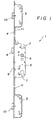
- the one shown in FIG. 1 and overall with 1 designated locking device consists of a Main lock box 2 and two additional lock boxes 3.
- the Lock boxes 2 and 3 are on a lock cuff 4 attached.
- the main lock box 2 is with a Box lid 5 closed and there is a follower 6, a locking cylinder 7, a latch 8 and a bolt 9 recognizable.
- the trap 8 is in the trap position, so that it from a striking plate shown in Figure 4 33, which is located on the door frame, in the Main lock box 2 can be pushed in.
- the latch 9 is in the closed position.
- the Additional lock boxes 3 are also each with a Provide traps which are designed as latch bolts 10.
- the latchbolts 10 are also in her Latch position and can thus from a striking plate 33rd are pressed into the respective additional locking box 3.
- a drive rod 11 can be seen, the Main lock box 2 with additional lock boxes 3 combines.
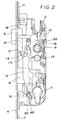
- the box cover 5 is removed, see above that the closing mechanism is recognizable.
- the from the lock cylinder 7 actuated change 12 the a bolt 13 on a slide 14 of an arm 15 one Control nut 16 attacks, recognizable.
- the slide 14 acts on a sliding stop 17 on one Control plate 18 is attached.
- the drive rod 11 hooked in at 19.
- the steering nut washer 16 has a further arm 20, which is on a trap foot 21 the case 8 is present.
- the spring force for the latch bolt 10 is from a Trap extension spring 28 ( Figure 3) applied to a Spring guide pin 29 is pushed on and one hand on the inner wall of the housing of the additional locking box 3, on the other hand supported on a latch extension lever 30.
- This latch extension lever 30 is in a bearing 31 pivoted. The one opposite the bearing 31 End of the latch extension lever 30 engages the Trigger nose 27 opposite end of the locking element 24 and pushes it under the power of Latch extension spring 28 in the extension direction. Since that Locking element 24 via the clamping sleeve 25 with the latch bolt 10 is connected, this is also in the extension direction crowded.
- the door is in its closed position and in alignment the latch bolt 10 to the latch opening 32 in Strike plate 33 on the door frame side (FIG. 4) fully inserted latchbolt 10 over the Latch extension lever 30 from the additional lock box 3 ejected.
- the locking element 24 against the direction of Pivoted clockwise around the clamping sleeve 25.
- the trigger nose 27 with the edge facing it Latch opening 32 of the striking plate 33 in contact, whereby the locking element 24 against the pivoting moment in the groove 23 is inserted so far that the locking lug 26 on the Castle cuff 4 can slide past.
- the latch position is the latch bolt 10 about 10 mm extended up to 15 mm further from the additional locking case 3, than in the trap position according to FIG. 1.
- the Trap extension lever 30 after pivoting the Locking element 24 bear directly on the latch bolt 10 and extend it into the locked position.
- the trap tail 34 a projection 35.
- a latch lock lever 37 pivotally mounted is and via a locking lever spring 38, which acts as a leg spring is formed, counterclockwise is spring-loaded.
- the latch bolt 10 is in the fully extended position according to Figures 3 and 4, i.e. in the locked position, then engages behind Trap locking edge 39 the projection 35. It can be between the projection 35 and the trap locking edge 39, as in FIG 3 shown, there is a small distance, but is effective the trap locking edge 39 in the displacement path of the projection 35th
- the latch bolt 10 is now e.g. using a tool or the like inserted into the additional locking box 3, the projection 35 comes to the trap locking edge 39 System and a further insertion is prevented. The Latch bolt 10 is thus in its locked position locked against insertion.
Claims (4)
- Dispositif de verrouillage (1) de porte, fenêtre ou similaire, comportant un palastre principal (2), au moins un palastre supplémentaire (3) et au moins une tringle (11) reliant le palastre supplémentaire (3) au palastre principal (2), le palastre supplémentaire (3) comprenant un pêne combiné demi-tour/dormant (10) qui peut, à partir de la position de pêne demi-tour, se rétracter librement dans le palastre supplémentaire (3) et qui peut être repoussé au-delà de la position normale de pêne demi-tour, jusqu'à sa position de verrouillage, par un ressort (28) et/ou un mécanisme de transmission, et le pêne combiné demi-tour/dormant (10) présentant, à l'opposé d'un pan incliné (22) et au niveau de la queue de pêne demi-tour (34), un ressaut (43) sur lequel agit un levier de rappel du pêne demi-tour (40), lequel présente un premier élément d'entraínement (46) par lequel une tringle (11) est entraínée dans l'un des sens, caractérisé en ce que le levier de rappel du pêne demi-tour (40) présente un second élément d'entraínement (47) qui le fait pivoter jusqu'à la position de verrouillage lors de la fermeture d'un pêne dormant principal (9), ladite fermeture entraínant la tringle (11) dans l'un des sens.
- Dispositif de verrouillage selon la revendication 1, caractérisé en ce que le second élément d'entraínement (47) est formé par une partie repliée ou coudée du levier de rappel du pêne demi-tour (40).
- Dispositif de verrouillage selon la revendication 1, caractérisé en ce que le second élément d'entraínement est formé par une pièce rapportée par soudage (48).
- Dispositif de verrouillage selon l'une quelconque des revendications précédentes, caractérisé en ce que le pêne dormant principal (9) présente un prolongement (49) agissant sur la tringle (11) lors de la fermeture.
Applications Claiming Priority (2)
| Application Number | Priority Date | Filing Date | Title |
|---|---|---|---|
| DE29718982U DE29718982U1 (de) | 1997-10-24 | 1997-10-24 | Verriegelungseinrichtung |
| DE29718982U | 1997-10-24 |
Publications (3)
| Publication Number | Publication Date |
|---|---|
| EP0911470A2 EP0911470A2 (fr) | 1999-04-28 |
| EP0911470A3 EP0911470A3 (fr) | 2001-05-30 |
| EP0911470B1 true EP0911470B1 (fr) | 2004-10-06 |
Family
ID=8047740
Family Applications (1)
| Application Number | Title | Priority Date | Filing Date |
|---|---|---|---|
| EP98114432A Expired - Lifetime EP0911470B1 (fr) | 1997-10-24 | 1998-08-01 | Dispositif de verrouillage |
Country Status (6)
| Country | Link |
|---|---|
| US (1) | US6327881B1 (fr) |
| EP (1) | EP0911470B1 (fr) |
| AT (1) | ATE278860T1 (fr) |
| DE (2) | DE29718982U1 (fr) |
| DK (1) | DK0911470T3 (fr) |
| ES (1) | ES2226041T3 (fr) |
Families Citing this family (37)
| Publication number | Priority date | Publication date | Assignee | Title |
|---|---|---|---|---|
| US6746060B2 (en) * | 2000-04-28 | 2004-06-08 | Ervos, Inc. | Tubular latch assembly for exit devices and locks |
| US6390515B1 (en) * | 2000-06-27 | 2002-05-21 | Mao-Lien Huang | Anti-theft latch |
| AUPR604601A0 (en) * | 2001-06-29 | 2001-07-26 | Gainsborough Hardware Industries Limited | A mortice lock |
| WO2005003494A1 (fr) * | 2003-07-04 | 2005-01-13 | Yarra Ridge Pty Ltd | Verrous |
| SG110175A1 (en) * | 2003-09-22 | 2005-04-28 | Lockwood Security Products Pty | A multipoint lock |
| DE10357721B4 (de) * | 2003-12-09 | 2008-08-21 | Schüring GmbH & Co. Fenstertechnologie KG | Verschlußvorrichtung für Türen oder Fenster |
| DE102004037915A1 (de) * | 2004-08-05 | 2006-02-23 | Roto Frank Ag | Verriegelungsvorrichtung zwischen einem Flügel und einem festen Rahmen einer Tür, eines Fensters oder dergleichen sowie Verriegelungsanordnung mit wenigstens einer derartigen Verriegelungsvorrichtung |
| DE102006057788A1 (de) * | 2005-12-07 | 2008-02-07 | KÜBLER, Klaus | Panikschloß zur Verwendung bei links- oder rechts anschlagenden Türen |
| US7878034B2 (en) * | 2007-02-02 | 2011-02-01 | Hoppe Holding Ag | Locking arrangement for a hinged panel |
| WO2008153707A2 (fr) | 2007-05-21 | 2008-12-18 | Truth Hardware Corporation | Mécanisme de verrouillage multipoint |
| TWM338888U (en) * | 2007-12-17 | 2008-08-21 | Imp Hardware Taiwan Ltd | Door lock having transmission mechanism |
| AU2009202988B2 (en) * | 2008-07-25 | 2015-06-25 | Allegion (Australia) Pty Ltd | Locks |
| US8899635B2 (en) * | 2008-10-03 | 2014-12-02 | Truth Hardware Corporation | Sliding door multipoint mortise lock with shoot bolts |
| US8348308B2 (en) | 2008-12-19 | 2013-01-08 | Amesbury Group, Inc. | High security lock for door |
| US8161780B1 (en) | 2009-01-16 | 2012-04-24 | G-U Hardware, Inc. | Thumb operated door lock assembly |
| CA2708912C (fr) * | 2009-06-30 | 2013-02-19 | Truth Hardware Corporation | Mecanisme de verrrouilage a mortaise a points multiples pour porte battante |
| US20120137742A1 (en) * | 2010-12-07 | 2012-06-07 | Securistyle Limited | Locking Device and Associated Methods |
| US8939474B2 (en) | 2011-06-03 | 2015-01-27 | Amesbury Group, Inc. | Lock with sliding locking elements |
| US9428937B2 (en) * | 2011-07-22 | 2016-08-30 | Amesbury Group, Inc. | Multi-point lock having sequentially-actuated locking elements |
| US9133650B1 (en) | 2011-08-04 | 2015-09-15 | Valentin Luca | Door closing latching mechanism |
| US9181736B1 (en) * | 2011-11-16 | 2015-11-10 | Valentin Luca | Compact door closing latching mechanism |
| BE1020811A3 (nl) * | 2012-05-07 | 2014-05-06 | Parys Remi E Van | Paniekslot. |
| WO2014036151A2 (fr) | 2012-08-31 | 2014-03-06 | Amesbury Group, Inc. | Mécanismes de verrou de porte passive |
| US9637957B2 (en) | 2012-11-06 | 2017-05-02 | Amesbury Group, Inc. | Automatically-extending remote door lock bolts |
| EP2921616B1 (fr) * | 2014-03-18 | 2017-07-19 | Gretsch-Unitas GmbH Baubeschläge | Dispositif pour une sortie de secours |
| AT515799B1 (de) * | 2014-03-31 | 2015-12-15 | Roto Frank Ag | Schloss |
| CN103993788A (zh) * | 2014-06-07 | 2014-08-20 | 李健 | 一种安全门锁体 |
| AU2015203396A1 (en) | 2014-06-20 | 2016-01-21 | Truth Hardware Corporation | Recessed lock actuating device for sliding doors |
| WO2016061473A1 (fr) | 2014-10-16 | 2016-04-21 | Bruce Hagemeyer | Verrou de porte coulissante à crochets opposés |
| US10968661B2 (en) | 2016-08-17 | 2021-04-06 | Amesbury Group, Inc. | Locking system having an electronic deadbolt |
| CA3059779A1 (fr) | 2017-04-18 | 2018-10-25 | Amesbury Group, Inc. | Systemes de pene dormant electroniques modulaires |
| US10808424B2 (en) | 2017-05-01 | 2020-10-20 | Amesbury Group, Inc. | Modular multi-point lock |
| US11066850B2 (en) | 2017-07-25 | 2021-07-20 | Amesbury Group, Inc | Access handle for sliding doors |
| CA3036398A1 (fr) | 2018-03-12 | 2019-09-12 | Amesbury Group, Inc. | Systemes de pene dormant electronique |
| US11834866B2 (en) | 2018-11-06 | 2023-12-05 | Amesbury Group, Inc. | Flexible coupling for electronic deadbolt systems |
| US11661771B2 (en) | 2018-11-13 | 2023-05-30 | Amesbury Group, Inc. | Electronic drive for door locks |
| GB2609203A (en) * | 2021-07-21 | 2023-02-01 | Ingenious Locks & Hardware Ltd | A lock system for a door or window |
Family Cites Families (12)
| Publication number | Priority date | Publication date | Assignee | Title |
|---|---|---|---|---|
| US536957A (en) * | 1895-04-02 | Bernhard klein | ||
| US512022A (en) * | 1894-01-02 | Eben n | ||
| US780181A (en) * | 1904-05-07 | 1905-01-17 | Merritt And Company | Locking device for the doors of lockers, &c. |
| US1706486A (en) * | 1927-05-19 | 1929-03-26 | Gasey Leo Lester | Dead-locking mechanism for door latches |
| FR2540170B1 (fr) * | 1983-01-28 | 1988-04-08 | Massard Jean Ets | Mecanisme de cremone-serrure de securite a double condamnation pour porte d'entree ou porte paliere |
| DE3505379C2 (de) * | 1985-02-16 | 1996-03-21 | Fliether Karl Gmbh & Co | Treibstangenschloß |
| GB8811734D0 (en) * | 1988-05-18 | 1988-06-22 | Goodwin W J & Son Ltd | Improvements in/relating to locking mechanisms |
| DE3836694C2 (de) * | 1988-10-28 | 1996-05-09 | Fliether Karl Gmbh & Co | Treibstangenschloß |
| DE8914367U1 (fr) | 1989-12-06 | 1991-04-04 | Bks Gmbh, 5620 Velbert, De | |
| AT400062B (de) * | 1993-03-26 | 1995-09-25 | Roto Frank Eisenwaren | Mehrriegelschloss |
| DE29500502U1 (de) * | 1995-01-13 | 1995-03-09 | Hoppe Ag | Mehrpunktverriegelung |
| DE29605517U1 (de) | 1996-03-26 | 1997-07-24 | Gretsch Unitas Gmbh | Verriegelungseinrichtung |
-
1997
- 1997-10-24 DE DE29718982U patent/DE29718982U1/de not_active Expired - Lifetime
-
1998
- 1998-08-01 DE DE59812079T patent/DE59812079D1/de not_active Expired - Lifetime
- 1998-08-01 DK DK98114432T patent/DK0911470T3/da active
- 1998-08-01 AT AT98114432T patent/ATE278860T1/de active
- 1998-08-01 ES ES98114432T patent/ES2226041T3/es not_active Expired - Lifetime
- 1998-08-01 EP EP98114432A patent/EP0911470B1/fr not_active Expired - Lifetime
- 1998-10-26 US US09/178,490 patent/US6327881B1/en not_active Expired - Fee Related
Also Published As
| Publication number | Publication date |
|---|---|
| DK0911470T3 (da) | 2005-02-07 |
| US6327881B1 (en) | 2001-12-11 |
| DE29718982U1 (de) | 1997-12-18 |
| ATE278860T1 (de) | 2004-10-15 |
| EP0911470A2 (fr) | 1999-04-28 |
| US20010047671A1 (en) | 2001-12-06 |
| EP0911470A3 (fr) | 2001-05-30 |
| ES2226041T3 (es) | 2005-03-16 |
| DE59812079D1 (de) | 2004-11-11 |
Similar Documents
| Publication | Publication Date | Title |
|---|---|---|
| EP0911470B1 (fr) | Dispositif de verrouillage | |
| EP0798436B1 (fr) | Dispositif de verrouillage | |
| EP0725198B1 (fr) | Fermeture à plusieurs pênes | |
| EP0796968B1 (fr) | Dispositif de fermeture | |
| EP0413177B1 (fr) | Serrure pour bielle motrice | |
| EP1970507B1 (fr) | Serrure anti-panique | |
| DE3836693A1 (de) | Treibstangenschloss | |
| EP3372757A1 (fr) | Unité de verrouillage pour une installation de verrouillage d'une porte | |
| EP0942135B2 (fr) | Dispositif de verrouillage | |
| EP0945572B1 (fr) | Ensemble de serrure de porte, de préférence crémone-serrure | |
| EP0204944B1 (fr) | Serrure de secours avec pêne, en particulier pour portes avec châssis tubulaire | |
| EP0954667B1 (fr) | Serrure a pene demi-tour pour porte ou fenetre | |
| DE102004012108B4 (de) | Treibstangenschloss für Türen, Fenster oder dergleichen mit Panikfunktion und Mehrpunktverriegelung | |
| DE102005039287A1 (de) | Antipanikschloss | |
| EP1049846B1 (fr) | Serrure pour porte en verre avec un element lateral fixe en verre | |
| EP0092630A1 (fr) | Engrenage de serrure pour battant de porte | |
| EP1624140B1 (fr) | Dispositif de verrouillage | |
| DE202005000939U1 (de) | Verriegelungseinrichtung | |
| DE102004013646A1 (de) | Panikschloss | |
| EP1031686B1 (fr) | Serrure avec un pêne demi-tour principal verrouillable actionné par une poignée | |
| DE2738746C3 (de) | Auslösevorrichtung für ein Paniktürschloß mit Falle und Riegel | |
| DE102007025723B3 (de) | Kupplungseinheit für ein Garagentor, insbesondere Kipp-, Schwenk- oder Sektionaltor | |
| DE102005021420A1 (de) | Einsteckschloss mit Fallensperre | |
| DE69722357T2 (de) | Verbesserungen an Schlössern | |
| DE3931101A1 (de) | Automatisch verriegelndes schloss |
Legal Events
| Date | Code | Title | Description |
|---|---|---|---|
| PUAI | Public reference made under article 153(3) epc to a published international application that has entered the european phase |
Free format text: ORIGINAL CODE: 0009012 |
|
| AK | Designated contracting states |
Kind code of ref document: A2 Designated state(s): AT BE CH DE DK ES FR GB IT LI NL |
|
| AX | Request for extension of the european patent |
Free format text: AL;LT;LV;MK;RO;SI |
|
| PUAL | Search report despatched |
Free format text: ORIGINAL CODE: 0009013 |
|
| AK | Designated contracting states |
Kind code of ref document: A3 Designated state(s): AT BE CH CY DE DK ES FI FR GB GR IE IT LI LU MC NL PT SE |
|
| AX | Request for extension of the european patent |
Free format text: AL;LT;LV;MK;RO;SI |
|
| 17P | Request for examination filed |
Effective date: 20010428 |
|
| AKX | Designation fees paid |
Free format text: AT BE CH DE DK ES FR GB IT LI NL |
|
| 17Q | First examination report despatched |
Effective date: 20030606 |
|
| GRAP | Despatch of communication of intention to grant a patent |
Free format text: ORIGINAL CODE: EPIDOSNIGR1 |
|
| RAP1 | Party data changed (applicant data changed or rights of an application transferred) |
Owner name: GRETSCH-UNITAS GMBH BAUBESCHLAEGE |
|
| GRAS | Grant fee paid |
Free format text: ORIGINAL CODE: EPIDOSNIGR3 |
|
| GRAA | (expected) grant |
Free format text: ORIGINAL CODE: 0009210 |
|
| AK | Designated contracting states |
Kind code of ref document: B1 Designated state(s): AT BE CH DE DK ES FR GB IT LI NL |
|
| REG | Reference to a national code |
Ref country code: GB Ref legal event code: FG4D Free format text: NOT ENGLISH |
|
| REG | Reference to a national code |
Ref country code: CH Ref legal event code: EP |
|
| GBT | Gb: translation of ep patent filed (gb section 77(6)(a)/1977) |
Effective date: 20041007 |
|
| REF | Corresponds to: |
Ref document number: 59812079 Country of ref document: DE Date of ref document: 20041111 Kind code of ref document: P |
|
| REG | Reference to a national code |
Ref country code: CH Ref legal event code: NV Representative=s name: TROESCH SCHEIDEGGER WERNER AG |
|
| REG | Reference to a national code |
Ref country code: DK Ref legal event code: T3 |
|
| REG | Reference to a national code |
Ref country code: ES Ref legal event code: FG2A Ref document number: 2226041 Country of ref document: ES Kind code of ref document: T3 |
|
| PLBE | No opposition filed within time limit |
Free format text: ORIGINAL CODE: 0009261 |
|
| STAA | Information on the status of an ep patent application or granted ep patent |
Free format text: STATUS: NO OPPOSITION FILED WITHIN TIME LIMIT |
|
| ET | Fr: translation filed | ||
| 26N | No opposition filed |
Effective date: 20050707 |
|
| PGFP | Annual fee paid to national office [announced via postgrant information from national office to epo] |
Ref country code: NL Payment date: 20080813 Year of fee payment: 11 Ref country code: ES Payment date: 20080828 Year of fee payment: 11 Ref country code: DK Payment date: 20080814 Year of fee payment: 11 Ref country code: CH Payment date: 20080814 Year of fee payment: 11 |
|
| PGFP | Annual fee paid to national office [announced via postgrant information from national office to epo] |
Ref country code: IT Payment date: 20080825 Year of fee payment: 11 Ref country code: FR Payment date: 20080813 Year of fee payment: 11 |
|
| PGFP | Annual fee paid to national office [announced via postgrant information from national office to epo] |
Ref country code: GB Payment date: 20080821 Year of fee payment: 11 |
|
| PGFP | Annual fee paid to national office [announced via postgrant information from national office to epo] |
Ref country code: BE Payment date: 20080918 Year of fee payment: 11 |
|
| BERE | Be: lapsed |
Owner name: *GRETSCH-UNITAS G.M.B.H. BAUBESCHLAGE Effective date: 20090831 |
|
| REG | Reference to a national code |
Ref country code: NL Ref legal event code: V1 Effective date: 20100301 Ref country code: CH Ref legal event code: PL |
|
| REG | Reference to a national code |
Ref country code: DK Ref legal event code: EBP |
|
| GBPC | Gb: european patent ceased through non-payment of renewal fee |
Effective date: 20090801 |
|
| PG25 | Lapsed in a contracting state [announced via postgrant information from national office to epo] |
Ref country code: LI Free format text: LAPSE BECAUSE OF NON-PAYMENT OF DUE FEES Effective date: 20090831 Ref country code: CH Free format text: LAPSE BECAUSE OF NON-PAYMENT OF DUE FEES Effective date: 20090831 |
|
| REG | Reference to a national code |
Ref country code: FR Ref legal event code: ST Effective date: 20100430 |
|
| PG25 | Lapsed in a contracting state [announced via postgrant information from national office to epo] |
Ref country code: BE Free format text: LAPSE BECAUSE OF NON-PAYMENT OF DUE FEES Effective date: 20090831 |
|
| PG25 | Lapsed in a contracting state [announced via postgrant information from national office to epo] |
Ref country code: NL Free format text: LAPSE BECAUSE OF NON-PAYMENT OF DUE FEES Effective date: 20100301 Ref country code: FR Free format text: LAPSE BECAUSE OF NON-PAYMENT OF DUE FEES Effective date: 20090831 Ref country code: DK Free format text: LAPSE BECAUSE OF NON-PAYMENT OF DUE FEES Effective date: 20090831 |
|
| REG | Reference to a national code |
Ref country code: ES Ref legal event code: FD2A Effective date: 20090803 |
|
| PG25 | Lapsed in a contracting state [announced via postgrant information from national office to epo] |
Ref country code: GB Free format text: LAPSE BECAUSE OF NON-PAYMENT OF DUE FEES Effective date: 20090801 |
|
| PG25 | Lapsed in a contracting state [announced via postgrant information from national office to epo] |
Ref country code: IT Free format text: LAPSE BECAUSE OF NON-PAYMENT OF DUE FEES Effective date: 20090801 |
|
| PG25 | Lapsed in a contracting state [announced via postgrant information from national office to epo] |
Ref country code: ES Free format text: LAPSE BECAUSE OF NON-PAYMENT OF DUE FEES Effective date: 20090802 |
|
| PGFP | Annual fee paid to national office [announced via postgrant information from national office to epo] |
Ref country code: DE Payment date: 20130821 Year of fee payment: 16 Ref country code: AT Payment date: 20130813 Year of fee payment: 16 |
|
| REG | Reference to a national code |
Ref country code: DE Ref legal event code: R119 Ref document number: 59812079 Country of ref document: DE |
|
| REG | Reference to a national code |
Ref country code: AT Ref legal event code: MM01 Ref document number: 278860 Country of ref document: AT Kind code of ref document: T Effective date: 20140801 |
|
| REG | Reference to a national code |
Ref country code: DE Ref legal event code: R119 Ref document number: 59812079 Country of ref document: DE Effective date: 20150303 |
|
| PG25 | Lapsed in a contracting state [announced via postgrant information from national office to epo] |
Ref country code: AT Free format text: LAPSE BECAUSE OF NON-PAYMENT OF DUE FEES Effective date: 20140801 |
|
| PG25 | Lapsed in a contracting state [announced via postgrant information from national office to epo] |
Ref country code: DE Free format text: LAPSE BECAUSE OF NON-PAYMENT OF DUE FEES Effective date: 20150303 |