EP1031686B1 - Serrure avec un pêne demi-tour principal verrouillable actionné par une poignée - Google Patents
Serrure avec un pêne demi-tour principal verrouillable actionné par une poignée Download PDFInfo
- Publication number
- EP1031686B1 EP1031686B1 EP00890036A EP00890036A EP1031686B1 EP 1031686 B1 EP1031686 B1 EP 1031686B1 EP 00890036 A EP00890036 A EP 00890036A EP 00890036 A EP00890036 A EP 00890036A EP 1031686 B1 EP1031686 B1 EP 1031686B1
- Authority
- EP
- European Patent Office
- Prior art keywords
- latch bolt
- auxiliary
- main
- bolt
- pin
- Prior art date
- Legal status (The legal status is an assumption and is not a legal conclusion. Google has not performed a legal analysis and makes no representation as to the accuracy of the status listed.)
- Expired - Lifetime
Links
Images

Classifications
-
- E—FIXED CONSTRUCTIONS
- E05—LOCKS; KEYS; WINDOW OR DOOR FITTINGS; SAFES
- E05B—LOCKS; ACCESSORIES THEREFOR; HANDCUFFS
- E05B63/00—Locks or fastenings with special structural characteristics
- E05B63/18—Locks or fastenings with special structural characteristics with arrangements independent of the locking mechanism for retaining the bolt or latch in the retracted position
- E05B63/20—Locks or fastenings with special structural characteristics with arrangements independent of the locking mechanism for retaining the bolt or latch in the retracted position released automatically when the wing is closed
-
- E—FIXED CONSTRUCTIONS
- E05—LOCKS; KEYS; WINDOW OR DOOR FITTINGS; SAFES
- E05B—LOCKS; ACCESSORIES THEREFOR; HANDCUFFS
- E05B55/00—Locks in which a sliding latch is used also as a locking bolt
- E05B55/12—Locks in which a sliding latch is used also as a locking bolt the bolt being secured by the operation of a hidden parallel member ; Automatic latch bolt deadlocking mechanisms, e.g. using a trigger or a feeler
-
- E—FIXED CONSTRUCTIONS
- E05—LOCKS; KEYS; WINDOW OR DOOR FITTINGS; SAFES
- E05B—LOCKS; ACCESSORIES THEREFOR; HANDCUFFS
- E05B63/00—Locks or fastenings with special structural characteristics
- E05B63/18—Locks or fastenings with special structural characteristics with arrangements independent of the locking mechanism for retaining the bolt or latch in the retracted position
- E05B63/20—Locks or fastenings with special structural characteristics with arrangements independent of the locking mechanism for retaining the bolt or latch in the retracted position released automatically when the wing is closed
- E05B2063/207—Automatic deadlocking
Definitions
- the invention relates to a lock with handle-operable and lockable main latch, which engages in a striker, and with an auxiliary latch which is inserted with the door closed by the striker and locks the main latch when inserted, the main latch in its fully extended position a locking device acted upon by the auxiliary latch and this holds in its extended position, wherein the inlet surface of the main case head of the inlet surface of the auxiliary case head is preceded for anticipatory release of the auxiliary case lock in the course of the closing process of the door, wherein in the closed position of the door with inserted auxiliary trap automatically by Spring force ausschiebbarer and is provided by a pusher and / or lock cylinder retractable latch, as well as a spring-loaded latch in the retracted position retaining tumbler, in particular a rocker , is associated with the latch, which is swung around when the auxiliary latch in the release position of the tumbler or rocker.
- a self-locking lock which has a latch and a biased by spring force in the locked position latch.
- the latch is held by a latch in the open position.
- the case holds the latch in the locked position and releases the latch only when the case is inserted and thereby the blocking of the latch is released.
- DE 37 00 891 A1 relates to a lock with a spring-loaded in the locking direction latch, which is held in the open position by a catch. The latter is triggered immediately by an auxiliary trap.
- EP 670 404 A1 discloses a self-locking lock with a spring-biased latch, a latch and an auxiliary latch that actuates a latch for holding the latch.
- a specially designed pivot lever is provided for blocking the auxiliary latch. This causes the blocking of the auxiliary trap as long as the trap is extended.
- the latch retracts and pivots the pivot lever so that the auxiliary latch can retreat. This retreat triggers the catch that has previously held back the latch.
- the bolt shoots forward and beats the front side against the lock plate in the latch pocket he finally engages.
- the invention aims to lock both the main latch when the door is closed and to release the latch as soon as it is in direct alignment with the latch pocket of the striker.
- the auxiliary latch is locked with the door open.
- a lock of the type described above in or on the shaft of the auxiliary latch a bolt or slide is slidably mounted, in the retracted position of the auxiliary latch on the one hand with one of the main latch when projecting the same trigger lever and on the other hand the tumbler, in particular rocker for the swinging kinematically aligned, so that only when in a case pocket of the closing piece projecting main latch of the latch is released to accelerate in his lock pocket of the striker.
- the pin performs a linear movement approximately parallel to the forend of the lock housing and can also be mounted on this forend.
- the pin is located on the head side on a control surface of the main catch or the main catch shaft, which raises the pin when the main catch is inserted. It may be provided between the pin and the main trap slot control, wherein a slider of the pin engages in the slot.
- auxiliary case approximately perpendicular to the insertion direction of the same in a bore a spring-mounted pin is mounted, the housing pin is in alignment with a housing fixed guide aligned housing pin opposite, wherein the housing pin of a control surface of the main trap against the pin in the auxiliary case is displaceable and this emerges from the bore in the auxiliary trap and the dividing plane between auxiliary trap and guide interspersed blocking.
- split pins are used, as they are known in tumblers in lock cylinders.
- the main catch or the shaft of the same acts as a control which displaces the pin ("housing pin") guided outside the auxiliary latch, which in turn pushes the guided in the auxiliary trap and spring-loaded pin axially and thus blocks the auxiliary trap.
- the control surface moves the housing pin when the main latch is pushed into a position in which the abutting end faces of the pins lie in the parting plane or sliding surface between the auxiliary latch and the housing-fixed guide of the housing pin.
- the locking device comprises a locking lever which engages with a control edge in a directed against the insertion direction surface, in particular to a stop of the auxiliary latch.
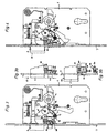
- Fig. 1 shows a lock with handle operable main latch and auxiliary latch that can be locked against incorrect operation, with the door open
- Fig. 2 the lock with the door closed
- Fig. 3 shows another embodiment of the auxiliary latch with the door open
- Fig. 3a shows a detail after Figure 4 shows a view according to Figure 3b, but including the main latch latch
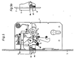
- Figure 5 shows another embodiment of the auxiliary latch latch with spring-loaded split pins when open
- Fig. 5a shows a detail when closing the door shortly after the first contact of the main latch with the striker
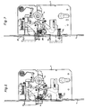
- Fig. 6 shows the complete lock according to the invention including the automatic latch with an auxiliary latch latch according to Fig. 5, with the door open and Fig. 7 the lock with the door closed with locked main latch and pushed out latch.
- a main catch 2 is mounted on and pushed out against the force of a spring 3. Via a nut 4, which has a corresponding control surface 5, the main trap 2 can be withdrawn by means of a pusher.
- an auxiliary trap 6 is spring-loaded against insertion.
- a spring is supported on the one hand on a bolt fixed to the housing and on the other hand on the inside of the auxiliary latch 5. Both cases 2 and 6 occur with the door open beyond a forend 7.
- the main trap 2 has a safety device that prevents it from being pushed in when the door is closed a plate-like burglary tool in the door gap, the main trap 2 can be pushed back. This safety device blocked with the door closed, the main case 2 in its extended position.
- the auxiliary latch 6 is scanned whether the door is closed, because the stock-side striker 37 (Fig. 2) provides a case for the intervention of the main case 2, but not such a case for the auxiliary case 6 before. The latter occupies the inserted position shown in Fig. 2 in the closed position of the door.
- Such safety devices for the main trap are known. Many of them work in such a way that the securing device and thus the blocking of the main trap 2 is activated by briefly pressing in the auxiliary latch 6. This remains activated, even if the auxiliary trap 6 exits again. Only by pressing the handle from the inside can the trap blocking be reversed. Thus, it can not be ruled out that when the door is open, someone strikes the auxiliary trap 6 and thus triggers the main trap blocking in the undesired time. However, this would mean that the next time you close the door, the blocked main case 2 does not retreat, so can not engage in the closing piece 37, but strikes it hard. As a result, lock and striker 37 are damaged.
- FIGS. 1 and 2 provide that when the door is open, the auxiliary latch 6 is locked and for the time being the main trap 2 are inserted a piece got to. It is not to be presumed that the two conditions for the activation of the lock of the main trap 2 actually occur in the intended order by chance.
- the auxiliary latch 6 has a stop 8 on which a control edge 9 of a locking lever 10 engages as soon as the main latch 2 is in its fully extended position.
- This situation shown in Fig. 1 causes the ejected auxiliary latch 6 (with the door open) can not be moved back and therefore is secured against incorrect operation. Only when the about the pivot point 11 pivotable locking lever 10 is rotated by a small angle to the right, lifts the control edge 9 from the stop 8 and the auxiliary latch 6 can be pushed back. This small rotation of the locking lever 10 is achieved by a slight pushing back of the main case 2, in which case shaft 12, a lever arm 13 of the locking lever 10 engages with some play.
- the inclined surface of the inlet slope of the main trap 2 is slightly ahead of the inclined surface of the inlet slope of the auxiliary trap 6.
- the inlet slope of the main trap 2 first with the striker in touch and is inserted first. If then a little later, the recessed inlet slope of the auxiliary latch 6 abuts against the closing piece, the already slightly hindergewichene main trap 2 has already twisted the locking lever 10 from the locking position for the auxiliary latch 6 and the auxiliary trap can recede unhindered. It has a contact surface 14, which extends after the stop 8 and engages a shoulder 15 of the locking lever 10 during insertion of the auxiliary latch 6.
- a cylindrical spring 16, each with a spring leg at the ends is pivotally mounted about a pin 17.
- the spring 16 and its legs is pivoted and these transmit a torque to a likewise pivotally mounted plate 18.
- the latter leads to the insertion of the auxiliary latch 6, mediated by the spring 16 with its two V-shaped spread legs, a Rotary movement, wherein a bearing surface 19 of this plate 18 is rotated to support under the second shoulder 20 of the locking lever 10.
- a bearing surface 19 of this plate 18 is rotated to support under the second shoulder 20 of the locking lever 10.
- Between the shoulders 15 and 20 is the fulcrum of the locking lever 10. If this is supported on both sides of its fulcrum by contact surfaces, then rotation of the locking lever 10 is excluded.
- the engaging in the case shaft 12 of the main case 2 lever arm 13 thus blocks the main case 2, so that it is secured against tampering and in particular against the attempt of insertion from the outside.
- FIGS. 3, 3a, 3b and 4 A completely different solution for a locking device which acts on the auxiliary latch 6 is shown in FIGS. 3, 3a, 3b and 4.
- FIG. A pin 30 is slidably mounted in a housing-fixed guide 31 against the force of a spring 32 along the cuff 7. The head of the pin 30 abuts against a control surface 33 of the main latch 2 and the main latch shaft 12, respectively. The pin 30 passes through the housing-fixed guide 31 and thereafter a slot-like clearance 34 in the auxiliary case 6. In the exit region of the pin 30, a collar 35 is attached to the pin 30, which according to FIG. 3, a step 36 on the auxiliary latch 6 directly opposite.
- both the main trap 2 and the auxiliary trap 6 are pushed out when the door is open.
- the control surface 33 holds the collar 35 in the insertion level of the auxiliary latch 6 at the level of the step 36.
- the auxiliary latch 6 can not be inserted.
- the slightly advanced inlet surface of the main trap 2 is pushed back by an edge of a closing piece 37, the pin 30 runs on a ramp of the control surface 33.
- the pin 30 is moved linearly against the force of the spring 32 and the collar 35 lifts off from the auxiliary latch 6, so that the stage 36 is now released. In the course of the further closing movement of the door and the auxiliary latch 6 can be inserted.
- the main trap 2 can not be pushed back. Only when due to handle operation, the plate 18 by a control edge of the nut 4 again in the direction of their 3 is turned back (game of the lever arm 13 'this locking lever 10' between the contact surfaces in the main traction shank 12), the main trap 2 can be retracted and the door can be opened.
- the auxiliary latch 6 springs out and is immediately blocked by the pin 30 or its collar 35 according to FIG. 3. The main trap 6 can therefore be inserted either accidentally (unintentionally) or intentionally with the door open.
- FIG. 5 A further alternative for a locking device is shown in FIG. 5.
- a housing-fixed guide 31 which continues in a bore in the auxiliary latch 6, a housing pin 38 and an auxiliary latch pin 39 are displaceably mounted against spring force.
- the housing pin 38 is located at one end to a control surface 33 of the main latch 2 and at the other end to the auxiliary latch pin 39 at.
- the auxiliary catch pin 39 is located with the door open in the dividing plane between the housing fixed guide 31 and auxiliary latch 6, whereby the auxiliary latch 6 is blocked.
- the door is open, it can not lead to malfunctions, for example as a result of unintentional insertion of the auxiliary latch 6.
- Fig. 5a shows this situation.
- the pin pair 38 and 39 is pushed back by the ramp in the control surface 33, and just so far that the contact surface between the pins 38 and 39 is located in the aforementioned division plane.
- the blocking of the auxiliary trap 6 is released.
- the auxiliary latch 6 can be pushed in by the closing piece in its entirety.
- FIG. 6 the locking device according to Fig. 5 and 5a in connection with the entire lock construction is shown by way of example.
- it could also be another locking device for the auxiliary trap 6 in their place.
- FIG. 6 the auxiliary trap blocking is shown analogously to FIG. With the door closed and pushed out the main trap 2, it can be seen that the pitched pins 38, 39 are shifted in the division plane to each other, since the auxiliary latch 6 is pushed back by the closing piece 37. Thus, as explained in connection with FIGS. 2 and 4, the main case 2 is locked.
- FIG. 6 In the course of closing the door, starting from Fig. 6 is the time-delayed release of the spring-loaded latch 21.
- This latch 21 is biased by a spring 22 in the direction of its blocking position, however, as shown in FIG. 6 by a rocker 23 (two-armed lever) in the retained retracted position.
- This rocker 23 is disposed below the auxiliary latch 6 and rotatably mounted about a pin fixed to the housing.
- a lever arm of the rocker 23 has a nose which engages in a recess of the bolt 21 and abuts there against a stop surface. When the rocker 23 swings, the nose lifts off the abutment surface; the latch 21 is released and jumps out under the action of the spring 22 via the forend 7 from the lock housing 1 out.
- a release lever 24 is provided in the form of a two-armed angle lever, on the one hand by a stop surface on the main catch shaft 12th is taken in the ejection movement.
- This release lever 24 sets the horizontal Ausschubterrorism the main case 2 in a vertical movement of a shaft mounted in the auxiliary case 6 bolt 25.
- the bolt 25 makes the horizontal movement of the auxiliary latch 6 so with. If the door is open (FIG. 6), then the bolt 25 has moved out of the kinematic connection to the release lever 24. But if the door is closed is (Fig. 7), then the pin axis is exactly aligned with the triggering edge of the trigger lever 24 and the pin 25 performs a thrusting movement, which is directed against the control edge of the rocker 23. Thus, a torque acts on the rocker 23; the rocker 23 pivots and her nose releases the latch 21, which now vorschnellt.
- the auxiliary latching shank may be provided with a guide, e.g. a dovetail on a flat side, be formed, in which a slider perpendicular to the direction of movement of the auxiliary latch 6 slides.
- Bolt 25 or slide are biased by a spring (not shown) so that they project beyond the auxiliary latch 6 and its shaft (Fig. 6).
- This spring may e.g. be provided on the axis of the rocker 23 and bias the rocker 23 in a clockwise direction.
- the above mechanism only comes into effect when the door is closed, the auxiliary latch 6 pushed back from the striker 37 and the main latch 2 is already on the way to the main case pocket of the striker 37 after being pushed back by the striker 37.
- the delayed lashing of the bolt 21 ensures that the latch 21 does not hit against the front side of the closing piece 37 and there along schleips until the door is completely closed, the latch can finally engage in the latch pocket. Rather, the latch 21 according to the invention is triggered only when its movement into the blocking position is no longer in the way.
- the plate 18 is part of a lever which is actuated by the nut 4 via a control surface. If, starting from Fig. 7, the nut 4 is rotated by a pusher clockwise by about 45 °, then pivots the plate 18 and provided in continuation of the plate 18 two-armed lever in the counterclockwise direction and pulls the latch 21 a.
- the operation can also be done by a lock cylinder in a known manner. A change, for example, the connection to the main case 2 ago while the closing lug of the lock cylinder causes the withdrawal of the bolt 21.
Landscapes
- Engineering & Computer Science (AREA)
- Structural Engineering (AREA)
- Lock And Its Accessories (AREA)
- Details Of Spanners, Wrenches, And Screw Drivers And Accessories (AREA)
- Telephone Function (AREA)
- Purses, Travelling Bags, Baskets, Or Suitcases (AREA)
- Toys (AREA)
- Steering Devices For Bicycles And Motorcycles (AREA)
- Breakers (AREA)
Claims (6)
- Serrure, avec un pêne principal (2) actionnable par poignée et verrouillable, s'encliquetant dans une gâche (37), ainsi qu'avec un pêne auxiliaire (6) qui, lorsque la porte est fermée, est inséré à travers la gâche (37) et qui, lors de l'insertion verrouille le pêne principal (2), sachant que le pêne principal (2) à sa position sortie en totalité sollicite un dispositif de blocage agissant sur le pêne auxiliaire (6) et maintient celui-ci à sa position sortie, la surface de rampe de la tête de pêne principale étant située en avant de la surface de rampe de la tête de pêne auxiliaire pour une libération anticipée du verrou à pêne auxiliaire au cours du processus de fermeture de la porte, un verrou (21) étant prévu qui, lorsque la porte est en position fermée alors que le pêne auxiliaire (6) est introduit, est susceptible d'être ressorti automatiquement par la force d'un ressort et est rétractable au moyen d'une poignée ou d'un cylindre de fermeture, et une gâchette fixant le verrou (21) précontraint élastiquement à la position rétractée, tel qu'en particulier une bascule, étant associée au verrou (21) qui, lorsque le pêne auxiliaire (6) est inséré est susceptible être commuté par pivotement à la position de libération de la gâchette ou de la bascule, sachant que dans ou sur la tige du pêne auxiliaire (6), une broche (25) ou un coulisseau est monté à coulissement et à la position introduite du pêne auxiliaire (6), d'une part avec un levier de déclenchement (24) actionnable par le pêne principal (2) lors de la sortie de celui-ci et d'autre part est aligné cinématiquement avec la gâchette, en particulier avec la bascule (23) pour produire sa manoeuvre de basculement par pivotement, de sorte qu'ensuite lorsque le pêne principal (2) est en saillie dans une poche pour pêne de la gâche (37), le verrou (21) soit libéré pour passer dans sa poche pour verrou de la gâche (37).
- Serrure selon la revendication 1, caractérisée en ce qu'est prévu comme dispositif de blocage entre le pêne principal (2) et le pêne auxiliaire (6) au moins une tige (30) déplaçable axialement et commandée par le pêne principal, tige qui, lorsque le pêne principal est inséré, est déplaçable depuis une position de blocage du pêne auxiliaire (6) et par exemple est soulevée par une surface d'appui située sur le pêne auxiliaire (6).
- Serrure selon la revendication 2, caractérisée en ce que la tige (30) s'appuie du côté tête sur une surface de commande (33) du pêne principal (2) ou de la tige (12) de pêne principal qui lors de l'insertion du pêne principal (2) soulève la tige (30) par rapport au pêne auxiliaire (6).
- Serrure selon la revendication 2, caractérisé en ce que dans le pêne auxiliaire (6) à peu près perpendiculairement à la direction d'insertion de celui-ci, dans un perçage est montée une tige (39) supportée élastiquement et à l'opposé de laquelle, lorsque le pêne principal (2) est sorti, est disposée en alignement une tige de boîtier (38) montée dans un guidage (31) fixé au boîtier, sachant que la tige de boîtier (38) est déplaçable par une surface de commande (33) du pêne principal (2) contre la tige (39) dans le pêne auxiliaire (6) et celle-ci sort du perçage ménagé dans le pêne auxiliaire (6) et traverse avec un effet de blocage le plan de division entre le pêne auxiliaire (6) et le guidage (31).
- Serrure selon la revendication 4, caractérisé en ce que la surface de commande (33), lorsque le pêne principal (2) est inséré déplace la tige de boîtier (38) en une position dans laquelle les faces frontales opposées des tiges (38, 39) sont situées dans le plan de division ou la face de glissement entre le pêne auxiliaire (6) et le guidage (31) fixé au boîtier de la tige de boîtier (38).
- Serrure selon la revendication 1, caractérisé en ce que le dispositif de blocage comprend un levier de blocage qui agit par une arête de commande sur une surface, tournée à l'encontre du sens d'insertion, en particulier sur une butée du pêne auxiliaire.
Priority Applications (1)
| Application Number | Priority Date | Filing Date | Title |
|---|---|---|---|
| AT00890036T ATE342415T1 (de) | 1999-02-24 | 2000-02-11 | Schloss mit drückerbetätigbarer und verriegelbarer hauptfalle |
Applications Claiming Priority (2)
| Application Number | Priority Date | Filing Date | Title |
|---|---|---|---|
| AT31799 | 1999-02-24 | ||
| AT0031799A AT407549B (de) | 1999-02-24 | 1999-02-24 | Schloss mit drückerbetätigbarer und verriegelbarer hauptfalle |
Publications (3)
| Publication Number | Publication Date |
|---|---|
| EP1031686A2 EP1031686A2 (fr) | 2000-08-30 |
| EP1031686A3 EP1031686A3 (fr) | 2001-06-27 |
| EP1031686B1 true EP1031686B1 (fr) | 2006-10-11 |
Family
ID=3487368
Family Applications (1)
| Application Number | Title | Priority Date | Filing Date |
|---|---|---|---|
| EP00890036A Expired - Lifetime EP1031686B1 (fr) | 1999-02-24 | 2000-02-11 | Serrure avec un pêne demi-tour principal verrouillable actionné par une poignée |
Country Status (4)
| Country | Link |
|---|---|
| EP (1) | EP1031686B1 (fr) |
| AT (2) | AT407549B (fr) |
| DE (1) | DE50013581D1 (fr) |
| ES (1) | ES2273662T3 (fr) |
Families Citing this family (9)
| Publication number | Priority date | Publication date | Assignee | Title |
|---|---|---|---|---|
| FI114497B (fi) * | 2003-05-14 | 2004-10-29 | Abloy Oy | Järjestely vinoteljen takalukituksen ohjaamiseksi ovenlukossa |
| DE102008011551B4 (de) * | 2008-02-28 | 2013-01-17 | Carl Fuhr Gmbh & Co. Kg | Selbstverriegelnde Zusatzverriegelung |
| DE102008032072A1 (de) | 2008-07-08 | 2010-01-14 | Assa Abloy Sicherheitstechnik Gmbh | Schließblech und Stulp und deren Verwendung |
| DE102010016313B4 (de) * | 2010-04-01 | 2013-05-29 | Sfs Intec Holding Ag | Schloss an einer mit einem Deckel verschließbaren Gepäckbox |
| DE102011081189A1 (de) * | 2011-08-18 | 2013-02-21 | Bombardier Transportation Gmbh | Schließvorrichtung für Fahrzeugtüren |
| CN109505466A (zh) * | 2018-12-30 | 2019-03-22 | 温州德诚锁业有限公司 | 一种无电关门自动上锁电控防盗锁 |
| FR3097581B1 (fr) * | 2019-06-18 | 2024-07-12 | Etablissements Devismes | Boitier de serrure à verrouillage automatique |
| DE102020205673B3 (de) * | 2020-05-05 | 2021-06-02 | Geze Gmbh | Selbstverriegelndes Schloss |
| GR1010491B (el) * | 2022-09-03 | 2023-06-16 | Κωνσταντινος Ιωαννη Πελεκας | Κλειδαρια εμποριου τυπου 'γλωσσου' που κλειδωνει αυτοματα σε καθε κλεισιμο της θυρας |
Family Cites Families (4)
| Publication number | Priority date | Publication date | Assignee | Title |
|---|---|---|---|---|
| DE215150C (fr) | ||||
| DE3700891A1 (de) | 1987-01-14 | 1987-06-19 | Geco Sicherungstechnik | Schloss |
| DE4407244C1 (de) * | 1994-03-04 | 1995-08-17 | Fuss Fritz Gmbh & Co | Selbstverriegelndes Schloß |
| DE19701761C1 (de) * | 1997-01-20 | 1998-04-16 | Fuss Fritz Gmbh & Co | Selbstverriegelndes Schloß |
-
1999
- 1999-02-24 AT AT0031799A patent/AT407549B/de not_active IP Right Cessation
-
2000
- 2000-02-11 AT AT00890036T patent/ATE342415T1/de active
- 2000-02-11 ES ES00890036T patent/ES2273662T3/es not_active Expired - Lifetime
- 2000-02-11 EP EP00890036A patent/EP1031686B1/fr not_active Expired - Lifetime
- 2000-02-11 DE DE50013581T patent/DE50013581D1/de not_active Expired - Lifetime
Also Published As
| Publication number | Publication date |
|---|---|
| ATE342415T1 (de) | 2006-11-15 |
| AT407549B (de) | 2001-04-25 |
| DE50013581D1 (de) | 2006-11-23 |
| EP1031686A3 (fr) | 2001-06-27 |
| ES2273662T3 (es) | 2007-05-16 |
| ATA31799A (de) | 2000-08-15 |
| EP1031686A2 (fr) | 2000-08-30 |
Similar Documents
| Publication | Publication Date | Title |
|---|---|---|
| DE19701761C1 (de) | Selbstverriegelndes Schloß | |
| EP0911470B1 (fr) | Dispositif de verrouillage | |
| EP0798436B1 (fr) | Dispositif de verrouillage | |
| EP1908900B1 (fr) | Serrure avec levier de déclenchement pivotant | |
| DE4446460C2 (de) | Türschloss, insbesondere für Automobile | |
| DE29719611U1 (de) | Schloß, insbesondere Einsteckschloß für eine Außentür | |
| EP2543802B1 (fr) | Serrure | |
| EP2862991B1 (fr) | Dispositif de verrouillage | |
| DE3836693A1 (de) | Treibstangenschloss | |
| EP1031686B1 (fr) | Serrure avec un pêne demi-tour principal verrouillable actionné par une poignée | |
| AT409397B (de) | Schloss | |
| DE102005021420A1 (de) | Einsteckschloss mit Fallensperre | |
| AT409286B (de) | Schloss | |
| EP2963213B1 (fr) | Serrure | |
| DE102008015655A1 (de) | Panikschloss | |
| DE3931101A1 (de) | Automatisch verriegelndes schloss | |
| AT357431B (de) | Tuerschloss | |
| EP3112564A1 (fr) | Serrure à loquet à verrouillage automatique | |
| DE202010006285U1 (de) | Einsteckschloss | |
| EP3216952B1 (fr) | Dispositif de verrouillage | |
| DE3741743A1 (de) | Sicherungsschalter | |
| DE3800298A1 (de) | Einsteckschloss | |
| DE19753234C2 (de) | Türschloß | |
| DE10129351A1 (de) | Schloss | |
| DE9207865U1 (de) | Durch einen Schlüssel- und/oder durch einen Drücker betätigbares Antipanik-Hotelschloß |
Legal Events
| Date | Code | Title | Description |
|---|---|---|---|
| PUAI | Public reference made under article 153(3) epc to a published international application that has entered the european phase |
Free format text: ORIGINAL CODE: 0009012 |
|
| AK | Designated contracting states |
Kind code of ref document: A2 Designated state(s): AT BE CH CY DE DK ES FI FR GB GR IE IT LI LU MC NL PT SE |
|
| AX | Request for extension of the european patent |
Free format text: AL;LT;LV;MK;RO;SI |
|
| PUAL | Search report despatched |
Free format text: ORIGINAL CODE: 0009013 |
|
| AK | Designated contracting states |
Kind code of ref document: A3 Designated state(s): AT BE CH CY DE DK ES FI FR GB GR IE IT LI LU MC NL PT SE |
|
| AX | Request for extension of the european patent |
Free format text: AL;LT;LV;MK;RO;SI |
|
| 17P | Request for examination filed |
Effective date: 20011210 |
|
| AKX | Designation fees paid |
Free format text: AT BE CH CY DE DK ES FI FR GB GR IE IT LI LU MC NL PT SE |
|
| RAP1 | Party data changed (applicant data changed or rights of an application transferred) |
Owner name: KABA GMBH |
|
| GRAP | Despatch of communication of intention to grant a patent |
Free format text: ORIGINAL CODE: EPIDOSNIGR1 |
|
| GRAS | Grant fee paid |
Free format text: ORIGINAL CODE: EPIDOSNIGR3 |
|
| GRAA | (expected) grant |
Free format text: ORIGINAL CODE: 0009210 |
|
| AK | Designated contracting states |
Kind code of ref document: B1 Designated state(s): AT BE CH CY DE DK ES FI FR GB GR IE IT LI LU MC NL PT SE |
|
| PG25 | Lapsed in a contracting state [announced via postgrant information from national office to epo] |
Ref country code: FI Free format text: LAPSE BECAUSE OF FAILURE TO SUBMIT A TRANSLATION OF THE DESCRIPTION OR TO PAY THE FEE WITHIN THE PRESCRIBED TIME-LIMIT Effective date: 20061011 Ref country code: IE Free format text: LAPSE BECAUSE OF FAILURE TO SUBMIT A TRANSLATION OF THE DESCRIPTION OR TO PAY THE FEE WITHIN THE PRESCRIBED TIME-LIMIT Effective date: 20061011 Ref country code: NL Free format text: LAPSE BECAUSE OF FAILURE TO SUBMIT A TRANSLATION OF THE DESCRIPTION OR TO PAY THE FEE WITHIN THE PRESCRIBED TIME-LIMIT Effective date: 20061011 |
|
| REG | Reference to a national code |
Ref country code: GB Ref legal event code: FG4D Free format text: NOT ENGLISH |
|
| REG | Reference to a national code |
Ref country code: CH Ref legal event code: EP |
|
| REG | Reference to a national code |
Ref country code: IE Ref legal event code: FG4D Free format text: LANGUAGE OF EP DOCUMENT: GERMAN |
|
| REF | Corresponds to: |
Ref document number: 50013581 Country of ref document: DE Date of ref document: 20061123 Kind code of ref document: P |
|
| REG | Reference to a national code |
Ref country code: CH Ref legal event code: NV Representative=s name: SCHNEIDER FELDMANN AG PATENT- UND MARKENANWAELTE |
|
| PG25 | Lapsed in a contracting state [announced via postgrant information from national office to epo] |
Ref country code: DK Free format text: LAPSE BECAUSE OF FAILURE TO SUBMIT A TRANSLATION OF THE DESCRIPTION OR TO PAY THE FEE WITHIN THE PRESCRIBED TIME-LIMIT Effective date: 20070111 Ref country code: SE Free format text: LAPSE BECAUSE OF FAILURE TO SUBMIT A TRANSLATION OF THE DESCRIPTION OR TO PAY THE FEE WITHIN THE PRESCRIBED TIME-LIMIT Effective date: 20070111 |
|
| PGFP | Annual fee paid to national office [announced via postgrant information from national office to epo] |
Ref country code: ES Payment date: 20070201 Year of fee payment: 8 |
|
| GBT | Gb: translation of ep patent filed (gb section 77(6)(a)/1977) |
Effective date: 20070111 |
|
| PG25 | Lapsed in a contracting state [announced via postgrant information from national office to epo] |
Ref country code: MC Free format text: LAPSE BECAUSE OF NON-PAYMENT OF DUE FEES Effective date: 20070228 |
|
| PG25 | Lapsed in a contracting state [announced via postgrant information from national office to epo] |
Ref country code: PT Free format text: LAPSE BECAUSE OF FAILURE TO SUBMIT A TRANSLATION OF THE DESCRIPTION OR TO PAY THE FEE WITHIN THE PRESCRIBED TIME-LIMIT Effective date: 20070319 |
|
| NLV1 | Nl: lapsed or annulled due to failure to fulfill the requirements of art. 29p and 29m of the patents act | ||
| ET | Fr: translation filed | ||
| REG | Reference to a national code |
Ref country code: ES Ref legal event code: FG2A Ref document number: 2273662 Country of ref document: ES Kind code of ref document: T3 Ref country code: IE Ref legal event code: FD4D |
|
| PLBE | No opposition filed within time limit |
Free format text: ORIGINAL CODE: 0009261 |
|
| STAA | Information on the status of an ep patent application or granted ep patent |
Free format text: STATUS: NO OPPOSITION FILED WITHIN TIME LIMIT |
|
| 26N | No opposition filed |
Effective date: 20070712 |
|
| BERE | Be: lapsed |
Owner name: KABA GMBH Effective date: 20070228 |
|
| PG25 | Lapsed in a contracting state [announced via postgrant information from national office to epo] |
Ref country code: BE Free format text: LAPSE BECAUSE OF NON-PAYMENT OF DUE FEES Effective date: 20070228 |
|
| PGFP | Annual fee paid to national office [announced via postgrant information from national office to epo] |
Ref country code: IT Payment date: 20070528 Year of fee payment: 8 |
|
| PG25 | Lapsed in a contracting state [announced via postgrant information from national office to epo] |
Ref country code: GR Free format text: LAPSE BECAUSE OF FAILURE TO SUBMIT A TRANSLATION OF THE DESCRIPTION OR TO PAY THE FEE WITHIN THE PRESCRIBED TIME-LIMIT Effective date: 20070112 |
|
| PGFP | Annual fee paid to national office [announced via postgrant information from national office to epo] |
Ref country code: FR Payment date: 20080205 Year of fee payment: 9 |
|
| REG | Reference to a national code |
Ref country code: ES Ref legal event code: FD2A Effective date: 20080212 |
|
| PG25 | Lapsed in a contracting state [announced via postgrant information from national office to epo] |
Ref country code: ES Free format text: LAPSE BECAUSE OF NON-PAYMENT OF DUE FEES Effective date: 20080212 |
|
| PG25 | Lapsed in a contracting state [announced via postgrant information from national office to epo] |
Ref country code: LU Free format text: LAPSE BECAUSE OF NON-PAYMENT OF DUE FEES Effective date: 20070211 Ref country code: CY Free format text: LAPSE BECAUSE OF FAILURE TO SUBMIT A TRANSLATION OF THE DESCRIPTION OR TO PAY THE FEE WITHIN THE PRESCRIBED TIME-LIMIT Effective date: 20061011 Ref country code: IT Free format text: LAPSE BECAUSE OF NON-PAYMENT OF DUE FEES Effective date: 20080211 |
|
| PGFP | Annual fee paid to national office [announced via postgrant information from national office to epo] |
Ref country code: CH Payment date: 20090525 Year of fee payment: 10 |
|
| REG | Reference to a national code |
Ref country code: FR Ref legal event code: ST Effective date: 20091030 |
|
| PG25 | Lapsed in a contracting state [announced via postgrant information from national office to epo] |
Ref country code: FR Free format text: LAPSE BECAUSE OF NON-PAYMENT OF DUE FEES Effective date: 20090302 |
|
| PGFP | Annual fee paid to national office [announced via postgrant information from national office to epo] |
Ref country code: GB Payment date: 20100118 Year of fee payment: 11 Ref country code: DE Payment date: 20100228 Year of fee payment: 11 |
|
| REG | Reference to a national code |
Ref country code: CH Ref legal event code: PL |
|
| PG25 | Lapsed in a contracting state [announced via postgrant information from national office to epo] |
Ref country code: LI Free format text: LAPSE BECAUSE OF NON-PAYMENT OF DUE FEES Effective date: 20100228 Ref country code: CH Free format text: LAPSE BECAUSE OF NON-PAYMENT OF DUE FEES Effective date: 20100228 |
|
| PGFP | Annual fee paid to national office [announced via postgrant information from national office to epo] |
Ref country code: AT Payment date: 20110228 Year of fee payment: 12 |
|
| GBPC | Gb: european patent ceased through non-payment of renewal fee |
Effective date: 20110211 |
|
| REG | Reference to a national code |
Ref country code: DE Ref legal event code: R119 Ref document number: 50013581 Country of ref document: DE Effective date: 20110901 |
|
| PG25 | Lapsed in a contracting state [announced via postgrant information from national office to epo] |
Ref country code: GB Free format text: LAPSE BECAUSE OF NON-PAYMENT OF DUE FEES Effective date: 20110211 |
|
| REG | Reference to a national code |
Ref country code: AT Ref legal event code: MM01 Ref document number: 342415 Country of ref document: AT Kind code of ref document: T Effective date: 20120211 |
|
| PG25 | Lapsed in a contracting state [announced via postgrant information from national office to epo] |
Ref country code: AT Free format text: LAPSE BECAUSE OF NON-PAYMENT OF DUE FEES Effective date: 20120211 |
|
| PG25 | Lapsed in a contracting state [announced via postgrant information from national office to epo] |
Ref country code: DE Free format text: LAPSE BECAUSE OF NON-PAYMENT OF DUE FEES Effective date: 20110901 |