EP0914665B1 - Elektromagnetisches relais und verfahren zu dessen herstellung - Google Patents
Elektromagnetisches relais und verfahren zu dessen herstellung Download PDFInfo
- Publication number
- EP0914665B1 EP0914665B1 EP97931621A EP97931621A EP0914665B1 EP 0914665 B1 EP0914665 B1 EP 0914665B1 EP 97931621 A EP97931621 A EP 97931621A EP 97931621 A EP97931621 A EP 97931621A EP 0914665 B1 EP0914665 B1 EP 0914665B1
- Authority
- EP
- European Patent Office
- Prior art keywords
- coil
- spring
- housing part
- contact
- armature
- Prior art date
- Legal status (The legal status is an assumption and is not a legal conclusion. Google has not performed a legal analysis and makes no representation as to the accuracy of the status listed.)
- Expired - Lifetime
Links
Images
Classifications
-
- H—ELECTRICITY
- H01—ELECTRIC ELEMENTS
- H01H—ELECTRIC SWITCHES; RELAYS; SELECTORS; EMERGENCY PROTECTIVE DEVICES
- H01H50/00—Details of electromagnetic relays
- H01H50/02—Bases; Casings; Covers
-
- H—ELECTRICITY
- H01—ELECTRIC ELEMENTS
- H01H—ELECTRIC SWITCHES; RELAYS; SELECTORS; EMERGENCY PROTECTIVE DEVICES
- H01H49/00—Apparatus or processes specially adapted to the manufacture of relays or parts thereof
-
- H—ELECTRICITY
- H01—ELECTRIC ELEMENTS
- H01H—ELECTRIC SWITCHES; RELAYS; SELECTORS; EMERGENCY PROTECTIVE DEVICES
- H01H50/00—Details of electromagnetic relays
- H01H50/14—Terminal arrangements
Definitions
- EP 0 531 890 A1 describes a switching relay, which basically a structure of the type mentioned having.
- the two housing parts do not form there closed housing, it is just about a base, which is preferably a printed circuit board with molded Is sidewall, and a lid part, between which too after the assembly, a large housing gap remains open.
- the relay there is preferably a multiple relay a series of magnet systems lying side by side, with a common core pole plate on the base lies and a series of vertically protruding core sections forms, on each of which a coil is attached.
- Each System also has a U-shaped anchor attached to the Core pole plate is mounted and the coil with the contact spring encloses in a frame shape.
- the cover part has slots inserted mating contact elements and spring supports, whereby these slots are also not tight. An adjustment the contacts are obviously made by the big one Housing opening in the area of the contacts.
- a relay is already known from WO 91/07770, in which the magnet system is fixed in the upper area of a housing while a contact system is from the open bottom is pushed in until the magnet system is excited Contact closes. After creating this contact system a desired overstroke by a predetermined amount inserted, it is fastened in the housing. On this way, manufacturing tolerances become apparent during assembly balanced, so that a subsequent adjustment is not more is needed.
- DE-A-2 506 626 describes a lockable with a housing, Contact carrier for switching elements made of insulating material known, anchor contacts either in a glass tube or attached in a plastic frame as a carrier are, these carriers to the outside through two housing caps be completed. All moving parts are in one and the same support part held while the housing caps no influence on the positioning of the functional elements of the relay.
- EP-A-0 251 035 also describes a relay which of two half-shell-shaped, forming a bobbin Basic body parts exist that carry the winding.
- Basic body parts In one of the basic body parts are in a common plane two pole plates embedded, the ends of which are in a contact space can be bridged within the coil by an armature contact.
- the anchor itself is in via a frame-shaped spring the parting plane between the two base parts.
- the aim of the present invention is to provide a relay of the input to create the type mentioned with a flat structure that for different sizes and applications is designed and that when using appropriate manufacturing processes in large Quantity can be produced very inexpensively. Due to the construction, a high level of accuracy is intended can already be achieved in production, so that even without Subsequent adjustment of the relay parameters with only small Scattering are observed.
- this goal is achieved with such a relay achieved in that the two housing parts as approximately trough-shaped half-shells made of plastic with their edges are sealed together that the connections for the Coil winding and for the contact elements each by the Wall of its associated housing part embedded to the outside are guided, and that the main joining planes between the two Housing parts perpendicular to the switching movement of the contact spring stand.
- the two half-shells form not just an easy-to-seal housing, but it also serve as carriers for the functional elements of the relay, these functional elements, i.e. the magnet system in one Part and the contact system in the other part already the manufacture of the respective half-shell positioned very precisely can be.
- the main joining planes are between two housing parts perpendicular to the switching movement of the Contact spring so that by joining the two housing parts the distance between the magnet system and contacts can be adjusted. Fixation is particularly easy of the functional parts in the housing and the sealing of the connections achieved in that this in the respective housing half-shell are embedded.
- the joining levels consist of Plastic, preferably thermoplastic, so that a tight connection, for example with ultrasound is easy to do.
- the magnet system from a U-shaped core yoke sheet, which is preferably as well as at least two coil connections in a plastic coil body are embedded.
- the on both ends of the Core formed pole plates then extend vertically to the coil axis in the area next to the coil, where it is from an armature lying next to the coil can be bridged.
- This Anchor can be designed more or less as a flat sheet be bent or bent at different heights at both ends to be offset accordingly in height as well Interacting pole plates. In this way, the Space in the housing for housing the contacts and the various connections can be used optimally.
- An L-shaped Contact spring which is front with a leg in front of the coil and with the other leg next to the coil Extending below or above the anchor results in a narrow space a large feather length; the anchor is preferably in the transition area between the two spring legs on the contact spring attached.
- a preferred method for producing the relay is that the first housing part is obtained by embedding the coil with the core, including the coil connections, according to the invention. that the second housing part is obtained by embedding the spring support and at least one counter-contact element, that the contact spring connected to the armature is connected to the spring support, and that the two housing parts are then placed on top of one another with their edges and connected.
- the coil former is also formed beforehand by embedding the core and the coil connections, with the first housing part being produced by a second embedding after winding the coil and after connecting the coil ends to the coil connections.
- the armature Before the two housing parts are joined together, the armature is connected to the contact spring, an electrically conductive connection by welding or the like or an insulating connection by overmolding being possible, depending on the application.
- the contact spring is then attached to the spring support anchored in the second housing part in an electrically conductive manner, for example by welding or also by means of a plug-in fastening.
- a major advantage of the invention can also be seen in the fact that that when joining the two housing parts, the contact lift can be set, for example, when joining measured the pull-through voltage of the anchor and then the joining process when reaching a predetermined electrical Characteristic value of the pull-through voltage - which is a measure of the erosion size or the overstroke of the contact is interrupted becomes.
- the two half-shells can be welded also with other technologies, for example by gluing, Clamping, casting or using a two-component injection molding process molded elostomer seal sealed become.
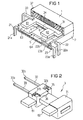
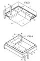
- the relay shown in Figures 1 to 5 consists of a first half-shell 1 and a second half-shell 2, the Half-shell 1 by overmolding a coil 3 and the second Half shell by overmolding a spring support 21 and two Mating contact elements 22 and 23 is formed.
- an L-shaped contact spring 4 is attached in turn carries an anchor 5.
- the almost Z-shaped curve Anchor 5 forms working air gaps with its ends with two pole faces 63 and 64 of the pole plates 61 and 62, which are part of a U-shaped core 6, but this Pole plate 62 is bent up from the core plane.
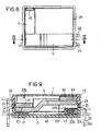
- the coil is first obtained by the middle section of the core 6 with thermoplastic material is overmolded, whereby a bobbin 31 is formed becomes.
- the pole plates 61 and 62 are kept free.
- two coil connections 32 in the coil body and 33 injected, so that not only the after externally directed pins 32a and 33a, but also the inner ones intended for contacting the winding ends Connecting surfaces 32b and 33b remain free of the embedding.
- After applying a coil winding 34 to the bobbin the ends of which are connected to the connecting surfaces 32b and 33b connected.
- the winding ends are protected guided behind ribs 35 in channels 36 of the bobbin.
- the entire coil is overmolded again, so to win the first half-shell according to FIG. 3.
- the pole faces 63 and 64 of the pole plates 61 and 62 also remain from this Overmolding free, while the rest of the parts, in particular also the coil winding 34, in the plastic 11 of the first Half shell 1 can be embedded.
- the coil connector pins 32a and 33a are close to the outside in this new embedding performed where it is angled downwards according to FIG. 1 or FIG. 3 or in a manner not shown, also for education from SMT connections in a horizontal plane can.
- the second half-shell 2 is, as already mentioned, by injection molding the spring support 21 and the mating contact elements 22 and 23 won, with a cavity for the coil and for the movable armature contact spring unit is free.
- the Mating contact elements each have a close to Outside guided pin 22a or 23a, while in Inside each a fixed contact section 32b or 33b with a Precious metal contact layer 32c or 33c is provided.
- the contact material in the The present example is the contact material as an inlay plated in the surface of the respective contact element, so that a cover when overmoulding easily possible is. Otherwise, other technologies would also apply of the contact material conceivable.
- the two mating contact elements 22 and 23 could of course only be a mating contact element to form an opener or a closer be provided.
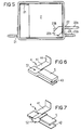
- the L-shaped contact spring 4 has a first Spring leg 41, which extends in front of the coil, and a second spring leg 42, which is laterally extends next to the coil below the armature and one movable contact 43 carries.
- the first spring leg 41 is via an upwardly angled fastening tab 44 the spring support 21 via a welded connection 46 according to FIG 4 or attached via a clamping claw 45 according to FIG. 8. Thanks to this connection technology, the mounting height is Contact spring 4 on the spring support 21 variable, which also the position of the second spring leg 42 relative to the mating contact elements can be adjusted. In this way the anchor restoring force or the rest contact force during the assembly process to compensate for tolerances become.
- the contact spring Before attaching the contact spring to the spring carrier 21 it is connected to the anchor 5, which, for example, according to 6 done electrically conductive via a welded joint 51 can. Should be insulation between the contact spring and the magnet system can be reached, so the connection made by an insulating material sheath 52 according to FIG. 7 become. For certain cases of use, it is also possible to conduct the current to the contact spring via a wire. For example, higher tax levels can be achieved through such Low-resistance wire to the contact point to to avoid excessive heating of the spring.
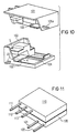
- FIG. 10 shows a variant of the relay from FIG. 1.
- the two half-shells 101 and 102 are not in a single joining plane, but with mutually graduated Joining planes 103 and 104 connected.
- the interior structure of the Relay is the same as in the previous example, except that a mating contact element, namely a normally open mating contact plate 105 with its pin 105a in the first half-shell is injected with the magnet system.
- a mating contact element namely a normally open mating contact plate 105 with its pin 105a in the first half-shell is injected with the magnet system.
- the distance between the two half-shells can be added the counter contacts are influenced.
- the construction of the relay allowed by the application of the relative parts also plan other embodiments of the connection geometry, so that the connections also on only one relay side can emerge from the housing.
- Such an opportunity is shown in Figure 11, with a first half-shell 110 the contact elements with pins 111, 112 and 113 and a second half shell 120 the magnet system with coil pins 121 and 122 carries.
- Such a relay is required only a small footprint for plugging or soldering.
- flat plugs can also be provided.
- the connector pins can of course also designed as surface-mountable SMT connections his.
Landscapes
- Physics & Mathematics (AREA)
- Electromagnetism (AREA)
- Engineering & Computer Science (AREA)
- Manufacturing & Machinery (AREA)
- Electromagnets (AREA)
- Manufacturing Of Electric Cables (AREA)
- Financial Or Insurance-Related Operations Such As Payment And Settlement (AREA)
- General Factory Administration (AREA)
Description
- einem ersten Gehäuseteil, der eine Spule sowie einen die Spule durchsetzenden, außerhalb der Spule an deren beiden Enden Polbleche bildenden Kern trägt,
- einem zweiten Gehäuseteil, in welchem mindestens ein Federträger sowie mindestens ein Gegenkontaktelement verankert sind, wobei der Federträger eine mit dem Gegenkontaktelement zusammenwirkende Kontaktfeder trägt, und
- einem Anker, der mit der Kontaktfeder verbunden ist und die Polbleche unter Bildung von Arbeitsluftspalten überbrückt. Außerdem betrifft die Erfindung ein Verfahren zur Herstellung eines solchen Relais.
daß der zweite Gehäuseteil durch Einbetten des Federträgers und mindestens einen Gegenkontaktelementes gewonnen wird, daß die mit dem Anker verbundene Kontaktfeder mit dem Federträger verbunden wird, und
daß dann die beiden Gehäuseteile mit ihren Rändern aufeinandergelegt und verbunden werden. Vorzugsweise wird dabei auch der Spulenkörper bereits vorher durch Einbetten des Kerns und der Spulenanschlüsse gebildet, wobei nach dem Wickeln der Spule und nach dem Verbinden der Spulenenden mit den Spulenanschlüssen durch eine zweite Einbettung der erste Gehäuseteil hergestellt wird. Vor dem Zusammenfügen der beiden Gehäuseteile wird der Anker mit der Kontaktfeder verbunden, wobei je nach dem Anwendungsfall eine elektrisch leitende Verbindung durch Schweißen oder dergleichen oder eine isolierende Verbindung durch Umspritzen möglich ist. Die Kontaktfeder wird dann an dem im zweiten Gehäuseteil verankerten Federträger elektrisch leitend befestigt, beispielsweise durch Schweißen oder auch über eine Steckbefestigung.
Claims (20)
- Elektromagnetisches Relais mitdadurch gekennzeichnet,einem ersten Gehäuseteil (1), der eine Spule (3) sowie einen die Spule durchsetzenden, außerhalb der Spule an deren beiden Enden Polbleche (61,62) bildenden Kern (6) trägt,einem zweiten Gehäuseteil (2), in welchem mindestens ein Federträger (21) sowie mindestens ein Gegenkontaktelement (22,23) verankert sind, wobei der Federträger (21) eine mit dem Gegenkontaktelement (22,23) zusammenwirkende Kontaktfeder (4) trägt, undeinem Anker (5), der mit der Kontaktfeder (4) verbunden ist und die Polbleche (61,62) unter Bildung von Arbeitsluftspalten überbrückt,daß die beiden Gehäuseteile (1,2) als annähernd wannenförmige Halbschalen aus Kunststoff mit ihren Rändern abdichtend zusammengefügt sind, daß die Anschlüsse (21a,22a,23a,32a,33a) für die Spulenwicklung (34) und für die Kontaktelemente (21,22,23) jeweils durch die Wand ihres zugehörigen Gehäuseteiles (1,2) eingebettet nach außen geführt sind, unddaß die Haupt-Fügeebenen zwischen beiden Gehäuseteilen (1,2) senkrecht zur Schaltbewegung der Kontaktfeder (4) stehen.
- Relais nach Anspruch 1,
dadurch gekennzeichnet, daß die aus einem Spulenkörper (31) mit Wicklung (34) gebildete Spule (3) zusammen mit dem Kern (6) in den Kunststoff des ersten Gehäuseteiles (1) - unter Freisparung von Polflächen (63,64) im Bereich der Arbeitsluftspalte - eingebettet ist, während der Federträger (21) und das mindestens eine Gegenkontaktelement (22,23) in den Kunststoff des zweiten Gehäuseteiles (2) eingebettet sind. - Relais nach Anspruch 2,
dadurch gekennzeichnet, daß der Kern (6) in den Kunststoff des Spulenkörpers (31) eingebettet ist. - Relais nach Anspruch 3,
dadurch gekennzeichnet, daß Anschlußelemente (32,33) für die Spulenwicklung (34) sowohl in den Spulenkörper (31) als auch in den Kunststoff des ersten Gehäuseteiles (1) eingebettet sind. - Relais nach einem der Ansprüche 1 bis 4,
dadurch gekennzeichnet, daß der Kern (6) U-förmig ist, wobei ein Mittelabschnitt die Spule (3) trägt und zwei Polbleche (61,62) im wesentlichen senkrecht zur Spulenachse abstehen und daß der Anker (5) sich im wesentlichen parallel zur Spulenachse neben der Spule (3) erstreckt und mit beiden Polblechen (61,62) die Arbeitsluftspalte bildet. - Relais nach Anspruch 5,
dadurch gekennzeichnet, daß die Kontaktfeder (4) L-förmig geschnitten ist, so daß sie zwei im wesentlichen in einer Ebene verlaufende Schenkel (41,42) besitzt, von denen sich der erste stirnseitig vor der Spule und der zweite seitlich neben der Spule erstreckt, wobei dieser zweite Schenkel (42) und der Anker (5) parallel übereinander liegen und im Eckbereich zwischen beiden Schenkeln der Kontaktfeder verbunden sind. - Relais nach Anspruch 6,
dadurch gekennzeichnet, daß der Anker (5) mit der Kontaktfeder (4) metallisch, nämlich durch Schweißen (51), Nieten oder dergleichen, verbunden ist. - Relais nach Anspruch 6,
dadurch gekennzeichnet, daß der Anker (5) mit der Kontaktfeder (4) über eine gemeinsame Isolierstoff-Umhüllung (52) verbunden ist. - Relais nach einem der Ansprüche 1 bis 8,
dadurch gekennzeichnet, daß in dem zweiten Gehäuseteil (2) zwei Gegenkontaktelemente (22,23) verankert sind, die mit der Kontaktfeder (4) einen Umschaltkontakt bilden. - Relais nach einem der Ansprüche 1 bis 8,
dadurch gekennzeichnet, daß ein zweites Gegenkontaktelement (105) in dem ersten Gehäuseteil (101) verankert ist, welches mit dem in dem zweiten Gehäuseteil (102) verankerten Gegenkontaktelement (23) und mit der Kontaktfeder (4) einen Umschaltkontakt bildet. - Relais nach einem der Ansprüche 1 bis 10,
dadurch gekennzeichnet, daß die beiden Gehäuseteile (1,2) mit abgestuft ausgebildeten Rändern (103,104) mindestens zwei gegeneinander parallel versetzte Trennebenen aufweisen. - Verfahren zur Herstellung eines Relais nach Anspruch 1, bei demdadurch gekennzeichnet,in einem ersten Gehäuseteil (1) eine Spule (3) sowie ein die Spule durchsetzender, außerhalb der Spule an deren beiden Enden Polbleche (61,62) bildender Kern (6) verankert wird,in einem zweiten Gehäuseteil (2) mindestens ein Federträger (21) und mindestens ein Gegenkontaktelement (22,23) verankert werden, wobei der Federträger (21) eine mit dem Gegenkontakt-element (22,23) zusammenwirkende Kontaktfeder (4) trägt, und bei demein Anker (5) mit der Kontaktfeder (4) verbunden ist und die Polbleche (61,62) unter Bildung von Arbeitsluftspalten überbrückt,wobei die beiden Gehäuseteile (1,2) jeweils wannenartig so ausgebildet werden, daß ihre Ränder mindestens eine Haupt-Fügeebene bilden, die senkrecht zur Bewegungsrichtung des Ankers steht,daß der erste Gehäuseteil (1) durch Einbetten der Spule (3) mit dem Kern (6) einschließlich der Spulenanschlüsse (32,33) gewonnen wird,daß der zweite Gehäuseteil (2) durch Einbetten des Federträgers (21) und mindestens eines Gegenkontaktelementes (22,23) gewonnen wird,daß die mit dem Anker (5) verbundene Kontaktfeder (4) mit dem Federträger (21) verbunden wird unddaß dann die beiden Gehäuseteile (1,2) mit ihren Rändern aufeinandergelegt und verbunden werden.
- Verfahren nach Anspruch 12,
dadurch gekennzeichnet, daß zunächst ein Spulenkörper (31) durch Einbetten des Kerns (6) und der Spulenanschlüsse (32,33) gebildet wird, daß dieser Spulenkörper (31) mit einer Spulenwicklung (34) versehen und dann zur Bildung des ersten Gehäuseteils (1) erneut eingebettet wird. - Verfahren nach Anspruch 12 oder 13,
dadurch gekennzeichnet, daß der Anker (5) mit der Kontaktfeder (4) durch Schweißen verbunden und letztere dann mit dem Federträger (21) verbunden wird. - Verfahren nach Anspruch 12 oder 13,
dadurch gekennzeichnet, daß der Anker (5) mit der Kontaktfeder (4) durch Einbettung in Isolierstoff (52) verbunden wird. - Relais nach einem der Ansprüche 12 bis 15,
dadurch gekennzeichnet, daß die Kontaktfeder (4) mit dem Federträger (21) durch Schweißen verbunden wird. - Relais nach einem der Ansprüche 12 bis 15,
dadurch gekennzeichnet, daß die Kontaktfeder (4) mit dem Federträger (21) durch Steckbefestigung verbunden wird. - Verfahren nach einem der Ansprüche 12 bis 17,
dadurch gekennzeichnet, daß beim Zusammenfügen beider Gehäuseteile (1,2) der Ankerhub und/oder der Überhub indirekt (elektrisch über die Durchzugsspannung) gemessen und bei Erreichen einer vorgegebenen Größe der Fügevorgang beendet wird. - Verfahren nach Anspruch 18,
dadurch gekennzeichnet, daß der Randbereich (25) zumindest einer der beiden Halbschalen (1) beim Fügen bis zum Erreichen des vorgegebenen Überhubes deformiert wird. - Verfahren nach Anspruch 19,
dadurch gekennzeichnet, daß der Rand bzw. eine am Rand angeformte Rippe (25) einer der beiden Halbschalen (1) beim Fügen durch Ultraschall verformt wird.
Applications Claiming Priority (3)
| Application Number | Priority Date | Filing Date | Title |
|---|---|---|---|
| DE19627844A DE19627844C1 (de) | 1996-07-10 | 1996-07-10 | Elektromagnetisches Relais und Verfahren zu dessen Herstellung |
| DE19627844 | 1996-07-10 | ||
| PCT/DE1997/001230 WO1998001880A1 (de) | 1996-07-10 | 1997-06-17 | Elektromagnetisches relais und verfahren zu dessen herstellung |
Publications (2)
| Publication Number | Publication Date |
|---|---|
| EP0914665A1 EP0914665A1 (de) | 1999-05-12 |
| EP0914665B1 true EP0914665B1 (de) | 2000-01-26 |
Family
ID=7799471
Family Applications (1)
| Application Number | Title | Priority Date | Filing Date |
|---|---|---|---|
| EP97931621A Expired - Lifetime EP0914665B1 (de) | 1996-07-10 | 1997-06-17 | Elektromagnetisches relais und verfahren zu dessen herstellung |
Country Status (7)
| Country | Link |
|---|---|
| US (1) | US6252479B1 (de) |
| EP (1) | EP0914665B1 (de) |
| JP (1) | JP2000514235A (de) |
| KR (1) | KR20000023651A (de) |
| AT (1) | ATE189334T1 (de) |
| DE (2) | DE19627844C1 (de) |
| WO (1) | WO1998001880A1 (de) |
Cited By (1)
| Publication number | Priority date | Publication date | Assignee | Title |
|---|---|---|---|---|
| ES2155383A1 (es) * | 1998-05-07 | 2001-05-01 | Siemens Electromech Components | Sistema magnetico para un rele electromagnetico. |
Families Citing this family (9)
| Publication number | Priority date | Publication date | Assignee | Title |
|---|---|---|---|---|
| WO2000007203A1 (de) * | 1998-07-27 | 2000-02-10 | Siemens Aktiengesellschaft | Schaltgerät mit einem gehäuseunterteil als baueinheit und zugehöriges fertigungsverfahren |
| DE10209810B4 (de) * | 2001-03-09 | 2006-11-16 | Omron Corporation | Relais |
| GB0110948D0 (en) * | 2001-05-04 | 2001-06-27 | Tyco Electronics Amp Gmbh | Bus controlled relays |
| JP4022440B2 (ja) * | 2002-07-01 | 2007-12-19 | 株式会社オートネットワーク技術研究所 | 回路ユニット |
| DE60305201T2 (de) * | 2002-11-15 | 2007-03-08 | Tyco Electronics Amp Gmbh | Magnetsystemumspritzung für ein relais |
| US7871984B2 (en) * | 2003-04-23 | 2011-01-18 | Yukio Sato | Methylated CpG polynucleotide |
| DE102012003236A1 (de) | 2012-02-20 | 2013-08-22 | Clariant Produkte (Deutschland) Gmbh | Vorvergoldung von Pd-Au-gecoateten Schalenkatalysatoren |
| CN110473743B (zh) * | 2019-04-25 | 2024-06-18 | 厦门宏发汽车电子有限公司 | 一种可保证衔铁或动簧片正常动作的继电器 |
| EP4002414A1 (de) * | 2020-11-13 | 2022-05-25 | Tyco Electronics Austria GmbH | Elektrisches gerät mit einem abgedichteten gehäuse mit einem gehäuseunterteil und einem gehäuseoberteil |
Family Cites Families (14)
| Publication number | Priority date | Publication date | Assignee | Title |
|---|---|---|---|---|
| FR1598789A (de) * | 1968-12-27 | 1970-07-06 | ||
| BE786042A (fr) * | 1970-12-02 | 1973-01-10 | Int Standard Electric Corp | Equipement de contact multipolaire place sous enveloppe scellee |
| DE2506626A1 (de) * | 1975-02-17 | 1976-08-26 | Hans Sauer | Mit einem gehaeuse abschliessbarer, aus isolierstoff bestehender kontakttraeger fuer schaltelemente |
| DE2622133A1 (de) * | 1976-05-18 | 1977-12-08 | Siemens Ag | Elektrisches bauelement, insbesondere elektromagnetisches relais |
| DE2723430C2 (de) * | 1977-05-24 | 1984-04-26 | Siemens AG, 1000 Berlin und 8000 München | Elektromagnetisches Relais |
| DE3378805D1 (en) | 1982-07-06 | 1989-02-02 | Nec Corp | Transfer-type electromagnetic relay |
| US4827234A (en) * | 1986-06-23 | 1989-05-02 | Siemens Aktiengesellschaft | Electromagnetic relay |
| US4975666A (en) * | 1989-03-28 | 1990-12-04 | Matsushita Electric Works, Ltd. | Polarized electromagnetic relay |
| EP0501951B1 (de) | 1989-11-16 | 1993-10-13 | Siemens Aktiengesellschaft | Elektromagnetisches relais |
| ATE95947T1 (de) * | 1989-11-16 | 1993-10-15 | Siemens Ag | Elektromagnetisches relais. |
| US5038123A (en) * | 1989-12-14 | 1991-08-06 | General Motors Corporation | Flat electromagnetic relay |
| US5191306A (en) * | 1990-09-14 | 1993-03-02 | Matsushita Electric Works, Ltd. | Miniature electromagnetic assembly and relay with the miniature electromagnet assembly |
| US5148136A (en) * | 1991-08-19 | 1992-09-15 | General Motors Corporation | Flat electromagnetic relay |
| US5216396A (en) * | 1991-09-13 | 1993-06-01 | Eaton Corporation | Switching relay |
-
1996
- 1996-07-10 DE DE19627844A patent/DE19627844C1/de not_active Expired - Fee Related
-
1997
- 1997-06-17 AT AT97931621T patent/ATE189334T1/de not_active IP Right Cessation
- 1997-06-17 WO PCT/DE1997/001230 patent/WO1998001880A1/de not_active Ceased
- 1997-06-17 DE DE59701074T patent/DE59701074D1/de not_active Expired - Lifetime
- 1997-06-17 JP JP10504638A patent/JP2000514235A/ja active Pending
- 1997-06-17 US US09/214,731 patent/US6252479B1/en not_active Expired - Fee Related
- 1997-06-17 EP EP97931621A patent/EP0914665B1/de not_active Expired - Lifetime
-
1999
- 1999-01-08 KR KR1019997000104A patent/KR20000023651A/ko not_active Withdrawn
Cited By (1)
| Publication number | Priority date | Publication date | Assignee | Title |
|---|---|---|---|---|
| ES2155383A1 (es) * | 1998-05-07 | 2001-05-01 | Siemens Electromech Components | Sistema magnetico para un rele electromagnetico. |
Also Published As
| Publication number | Publication date |
|---|---|
| DE59701074D1 (de) | 2000-03-02 |
| JP2000514235A (ja) | 2000-10-24 |
| WO1998001880A1 (de) | 1998-01-15 |
| KR20000023651A (ko) | 2000-04-25 |
| EP0914665A1 (de) | 1999-05-12 |
| ATE189334T1 (de) | 2000-02-15 |
| DE19627844C1 (de) | 1997-08-28 |
| US6252479B1 (en) | 2001-06-26 |
Similar Documents
| Publication | Publication Date | Title |
|---|---|---|
| DE60018502T2 (de) | Elektromagnetisches Relais | |
| DE19747167C1 (de) | Elektromagnetisches Relais | |
| DE3829035C2 (de) | ||
| EP0914665B1 (de) | Elektromagnetisches relais und verfahren zu dessen herstellung | |
| EP1025573B1 (de) | Verfahren zur herstellung eines relais | |
| EP0758484B1 (de) | Modulrelais | |
| EP0017129B2 (de) | Gepoltes Zungenkontaktrelais | |
| DE69735239T2 (de) | Hochfrequenzschalter | |
| EP0713233A2 (de) | Anordnung eines Relais mit einem Steckadapter und Verfahren zur Herstellung dieser Anordnung | |
| DE2353444A1 (de) | In isolierstoff eingebettetes elektromatnetisches relais | |
| DE4310369A1 (de) | Adapter | |
| EP0308819B1 (de) | Elektromagnetisches Relais | |
| EP0910861B1 (de) | Verfahren zur herstellung eines elektromagnetischen relais | |
| EP0858670A2 (de) | Elektrischer kontaktschalter | |
| DE3435823C2 (de) | Verfahren zur Herstellung von Klinkensteckerbuchsen | |
| DE10304445A1 (de) | Anschlussaufbau eines Hochfrequenzübertragungsteils | |
| DE3025814A1 (de) | Elektromagnetisches relais | |
| EP0487786A2 (de) | Relais | |
| EP0410984B1 (de) | Spulenkörper und verfahren zur hestellung eines spulenkörpers | |
| EP0502842B1 (de) | Elektromagnetisches relais | |
| EP0056840B1 (de) | Elektromagnetisches Relais | |
| DE19511877A1 (de) | Kontakteinheit, insbesondere für elektrische Schalter | |
| DE19820458C1 (de) | Magnetsystem für ein elektromagnetisches Relais | |
| DE4423395A1 (de) | Elektrische Flachsteckeranordnung für Kraftfahrzeuge und Verfahren zur Herstellung der elektrischen Flachsteckeranordnung | |
| DE4415929A1 (de) | Modulrelais |
Legal Events
| Date | Code | Title | Description |
|---|---|---|---|
| PUAI | Public reference made under article 153(3) epc to a published international application that has entered the european phase |
Free format text: ORIGINAL CODE: 0009012 |
|
| 17P | Request for examination filed |
Effective date: 19990105 |
|
| AK | Designated contracting states |
Kind code of ref document: A1 Designated state(s): AT CH DE FR GB IT LI |
|
| GRAG | Despatch of communication of intention to grant |
Free format text: ORIGINAL CODE: EPIDOS AGRA |
|
| GRAG | Despatch of communication of intention to grant |
Free format text: ORIGINAL CODE: EPIDOS AGRA |
|
| GRAH | Despatch of communication of intention to grant a patent |
Free format text: ORIGINAL CODE: EPIDOS IGRA |
|
| 17Q | First examination report despatched |
Effective date: 19990623 |
|
| GRAH | Despatch of communication of intention to grant a patent |
Free format text: ORIGINAL CODE: EPIDOS IGRA |
|
| GRAA | (expected) grant |
Free format text: ORIGINAL CODE: 0009210 |
|
| AK | Designated contracting states |
Kind code of ref document: B1 Designated state(s): AT CH DE FR GB IT LI |
|
| REF | Corresponds to: |
Ref document number: 189334 Country of ref document: AT Date of ref document: 20000215 Kind code of ref document: T |
|
| REG | Reference to a national code |
Ref country code: CH Ref legal event code: EP |
|
| REF | Corresponds to: |
Ref document number: 59701074 Country of ref document: DE Date of ref document: 20000302 |
|
| ITF | It: translation for a ep patent filed | ||
| ET | Fr: translation filed | ||
| GBT | Gb: translation of ep patent filed (gb section 77(6)(a)/1977) |
Effective date: 20000330 |
|
| PG25 | Lapsed in a contracting state [announced via postgrant information from national office to epo] |
Ref country code: AT Free format text: LAPSE BECAUSE OF NON-PAYMENT OF DUE FEES Effective date: 20000617 |
|
| PLBE | No opposition filed within time limit |
Free format text: ORIGINAL CODE: 0009261 |
|
| STAA | Information on the status of an ep patent application or granted ep patent |
Free format text: STATUS: NO OPPOSITION FILED WITHIN TIME LIMIT |
|
| 26N | No opposition filed | ||
| REG | Reference to a national code |
Ref country code: GB Ref legal event code: 732E |
|
| PGFP | Annual fee paid to national office [announced via postgrant information from national office to epo] |
Ref country code: GB Payment date: 20010502 Year of fee payment: 5 |
|
| PGFP | Annual fee paid to national office [announced via postgrant information from national office to epo] |
Ref country code: FR Payment date: 20010531 Year of fee payment: 5 |
|
| PG25 | Lapsed in a contracting state [announced via postgrant information from national office to epo] |
Ref country code: LI Free format text: LAPSE BECAUSE OF NON-PAYMENT OF DUE FEES Effective date: 20010630 Ref country code: CH Free format text: LAPSE BECAUSE OF NON-PAYMENT OF DUE FEES Effective date: 20010630 |
|
| REG | Reference to a national code |
Ref country code: GB Ref legal event code: IF02 |
|
| REG | Reference to a national code |
Ref country code: CH Ref legal event code: PL |
|
| PG25 | Lapsed in a contracting state [announced via postgrant information from national office to epo] |
Ref country code: GB Free format text: LAPSE BECAUSE OF NON-PAYMENT OF DUE FEES Effective date: 20020617 |
|
| GBPC | Gb: european patent ceased through non-payment of renewal fee |
Effective date: 20020617 |
|
| PG25 | Lapsed in a contracting state [announced via postgrant information from national office to epo] |
Ref country code: FR Free format text: LAPSE BECAUSE OF NON-PAYMENT OF DUE FEES Effective date: 20030228 |
|
| REG | Reference to a national code |
Ref country code: FR Ref legal event code: ST |
|
| PG25 | Lapsed in a contracting state [announced via postgrant information from national office to epo] |
Ref country code: IT Free format text: LAPSE BECAUSE OF NON-PAYMENT OF DUE FEES;WARNING: LAPSES OF ITALIAN PATENTS WITH EFFECTIVE DATE BEFORE 2007 MAY HAVE OCCURRED AT ANY TIME BEFORE 2007. THE CORRECT EFFECTIVE DATE MAY BE DIFFERENT FROM THE ONE RECORDED. Effective date: 20050617 |
|
| PGFP | Annual fee paid to national office [announced via postgrant information from national office to epo] |
Ref country code: DE Payment date: 20140627 Year of fee payment: 18 |
|
| REG | Reference to a national code |
Ref country code: DE Ref legal event code: R119 Ref document number: 59701074 Country of ref document: DE |
|
| PG25 | Lapsed in a contracting state [announced via postgrant information from national office to epo] |
Ref country code: DE Free format text: LAPSE BECAUSE OF NON-PAYMENT OF DUE FEES Effective date: 20160101 |