EP0914665B1 - Electromagnetic relay and process for producing the same - Google Patents
Electromagnetic relay and process for producing the same Download PDFInfo
- Publication number
- EP0914665B1 EP0914665B1 EP97931621A EP97931621A EP0914665B1 EP 0914665 B1 EP0914665 B1 EP 0914665B1 EP 97931621 A EP97931621 A EP 97931621A EP 97931621 A EP97931621 A EP 97931621A EP 0914665 B1 EP0914665 B1 EP 0914665B1
- Authority
- EP
- European Patent Office
- Prior art keywords
- coil
- spring
- housing part
- contact
- armature
- Prior art date
- Legal status (The legal status is an assumption and is not a legal conclusion. Google has not performed a legal analysis and makes no representation as to the accuracy of the status listed.)
- Expired - Lifetime
Links
- 238000000034 method Methods 0.000 title claims description 13
- 230000013011 mating Effects 0.000 claims abstract description 20
- 238000005304 joining Methods 0.000 claims abstract description 18
- 238000004804 winding Methods 0.000 claims description 11
- 239000004033 plastic Substances 0.000 claims description 10
- 238000004519 manufacturing process Methods 0.000 claims description 8
- 238000003466 welding Methods 0.000 claims description 6
- 238000002604 ultrasonography Methods 0.000 claims description 4
- 238000005516 engineering process Methods 0.000 description 3
- 238000001746 injection moulding Methods 0.000 description 3
- 239000000969 carrier Substances 0.000 description 2
- 238000010276 construction Methods 0.000 description 2
- 230000003628 erosive effect Effects 0.000 description 2
- 239000011810 insulating material Substances 0.000 description 2
- 239000000463 material Substances 0.000 description 2
- 238000004026 adhesive bonding Methods 0.000 description 1
- 230000015572 biosynthetic process Effects 0.000 description 1
- 238000005266 casting Methods 0.000 description 1
- 210000000078 claw Anatomy 0.000 description 1
- 238000007765 extrusion coating Methods 0.000 description 1
- 210000003746 feather Anatomy 0.000 description 1
- 239000011521 glass Substances 0.000 description 1
- 238000010438 heat treatment Methods 0.000 description 1
- 238000002347 injection Methods 0.000 description 1
- 239000007924 injection Substances 0.000 description 1
- 238000009413 insulation Methods 0.000 description 1
- 230000004048 modification Effects 0.000 description 1
- 238000012986 modification Methods 0.000 description 1
- 230000002093 peripheral effect Effects 0.000 description 1
- 239000010970 precious metal Substances 0.000 description 1
- 238000007789 sealing Methods 0.000 description 1
- 229910000679 solder Inorganic materials 0.000 description 1
- 238000005476 soldering Methods 0.000 description 1
- 229920001169 thermoplastic Polymers 0.000 description 1
- 239000012815 thermoplastic material Substances 0.000 description 1
- 239000004416 thermosoftening plastic Substances 0.000 description 1
- 230000007704 transition Effects 0.000 description 1
Images
Classifications
-
- H—ELECTRICITY
- H01—ELECTRIC ELEMENTS
- H01H—ELECTRIC SWITCHES; RELAYS; SELECTORS; EMERGENCY PROTECTIVE DEVICES
- H01H50/00—Details of electromagnetic relays
- H01H50/02—Bases; Casings; Covers
-
- H—ELECTRICITY
- H01—ELECTRIC ELEMENTS
- H01H—ELECTRIC SWITCHES; RELAYS; SELECTORS; EMERGENCY PROTECTIVE DEVICES
- H01H49/00—Apparatus or processes specially adapted to the manufacture of relays or parts thereof
-
- H—ELECTRICITY
- H01—ELECTRIC ELEMENTS
- H01H—ELECTRIC SWITCHES; RELAYS; SELECTORS; EMERGENCY PROTECTIVE DEVICES
- H01H50/00—Details of electromagnetic relays
- H01H50/14—Terminal arrangements
Definitions
- EP 0 531 890 A1 describes a switching relay, which basically a structure of the type mentioned having.
- the two housing parts do not form there closed housing, it is just about a base, which is preferably a printed circuit board with molded Is sidewall, and a lid part, between which too after the assembly, a large housing gap remains open.
- the relay there is preferably a multiple relay a series of magnet systems lying side by side, with a common core pole plate on the base lies and a series of vertically protruding core sections forms, on each of which a coil is attached.
- Each System also has a U-shaped anchor attached to the Core pole plate is mounted and the coil with the contact spring encloses in a frame shape.
- the cover part has slots inserted mating contact elements and spring supports, whereby these slots are also not tight. An adjustment the contacts are obviously made by the big one Housing opening in the area of the contacts.
- a relay is already known from WO 91/07770, in which the magnet system is fixed in the upper area of a housing while a contact system is from the open bottom is pushed in until the magnet system is excited Contact closes. After creating this contact system a desired overstroke by a predetermined amount inserted, it is fastened in the housing. On this way, manufacturing tolerances become apparent during assembly balanced, so that a subsequent adjustment is not more is needed.
- DE-A-2 506 626 describes a lockable with a housing, Contact carrier for switching elements made of insulating material known, anchor contacts either in a glass tube or attached in a plastic frame as a carrier are, these carriers to the outside through two housing caps be completed. All moving parts are in one and the same support part held while the housing caps no influence on the positioning of the functional elements of the relay.
- EP-A-0 251 035 also describes a relay which of two half-shell-shaped, forming a bobbin Basic body parts exist that carry the winding.
- Basic body parts In one of the basic body parts are in a common plane two pole plates embedded, the ends of which are in a contact space can be bridged within the coil by an armature contact.
- the anchor itself is in via a frame-shaped spring the parting plane between the two base parts.
- the aim of the present invention is to provide a relay of the input to create the type mentioned with a flat structure that for different sizes and applications is designed and that when using appropriate manufacturing processes in large Quantity can be produced very inexpensively. Due to the construction, a high level of accuracy is intended can already be achieved in production, so that even without Subsequent adjustment of the relay parameters with only small Scattering are observed.
- this goal is achieved with such a relay achieved in that the two housing parts as approximately trough-shaped half-shells made of plastic with their edges are sealed together that the connections for the Coil winding and for the contact elements each by the Wall of its associated housing part embedded to the outside are guided, and that the main joining planes between the two Housing parts perpendicular to the switching movement of the contact spring stand.
- the two half-shells form not just an easy-to-seal housing, but it also serve as carriers for the functional elements of the relay, these functional elements, i.e. the magnet system in one Part and the contact system in the other part already the manufacture of the respective half-shell positioned very precisely can be.
- the main joining planes are between two housing parts perpendicular to the switching movement of the Contact spring so that by joining the two housing parts the distance between the magnet system and contacts can be adjusted. Fixation is particularly easy of the functional parts in the housing and the sealing of the connections achieved in that this in the respective housing half-shell are embedded.
- the joining levels consist of Plastic, preferably thermoplastic, so that a tight connection, for example with ultrasound is easy to do.
- the magnet system from a U-shaped core yoke sheet, which is preferably as well as at least two coil connections in a plastic coil body are embedded.
- the on both ends of the Core formed pole plates then extend vertically to the coil axis in the area next to the coil, where it is from an armature lying next to the coil can be bridged.
- This Anchor can be designed more or less as a flat sheet be bent or bent at different heights at both ends to be offset accordingly in height as well Interacting pole plates. In this way, the Space in the housing for housing the contacts and the various connections can be used optimally.
- An L-shaped Contact spring which is front with a leg in front of the coil and with the other leg next to the coil Extending below or above the anchor results in a narrow space a large feather length; the anchor is preferably in the transition area between the two spring legs on the contact spring attached.
- a preferred method for producing the relay is that the first housing part is obtained by embedding the coil with the core, including the coil connections, according to the invention. that the second housing part is obtained by embedding the spring support and at least one counter-contact element, that the contact spring connected to the armature is connected to the spring support, and that the two housing parts are then placed on top of one another with their edges and connected.
- the coil former is also formed beforehand by embedding the core and the coil connections, with the first housing part being produced by a second embedding after winding the coil and after connecting the coil ends to the coil connections.
- the armature Before the two housing parts are joined together, the armature is connected to the contact spring, an electrically conductive connection by welding or the like or an insulating connection by overmolding being possible, depending on the application.
- the contact spring is then attached to the spring support anchored in the second housing part in an electrically conductive manner, for example by welding or also by means of a plug-in fastening.
- a major advantage of the invention can also be seen in the fact that that when joining the two housing parts, the contact lift can be set, for example, when joining measured the pull-through voltage of the anchor and then the joining process when reaching a predetermined electrical Characteristic value of the pull-through voltage - which is a measure of the erosion size or the overstroke of the contact is interrupted becomes.
- the two half-shells can be welded also with other technologies, for example by gluing, Clamping, casting or using a two-component injection molding process molded elostomer seal sealed become.
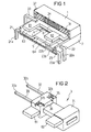
- the relay shown in Figures 1 to 5 consists of a first half-shell 1 and a second half-shell 2, the Half-shell 1 by overmolding a coil 3 and the second Half shell by overmolding a spring support 21 and two Mating contact elements 22 and 23 is formed.
- an L-shaped contact spring 4 is attached in turn carries an anchor 5.
- the almost Z-shaped curve Anchor 5 forms working air gaps with its ends with two pole faces 63 and 64 of the pole plates 61 and 62, which are part of a U-shaped core 6, but this Pole plate 62 is bent up from the core plane.
- the coil is first obtained by the middle section of the core 6 with thermoplastic material is overmolded, whereby a bobbin 31 is formed becomes.
- the pole plates 61 and 62 are kept free.
- two coil connections 32 in the coil body and 33 injected, so that not only the after externally directed pins 32a and 33a, but also the inner ones intended for contacting the winding ends Connecting surfaces 32b and 33b remain free of the embedding.
- After applying a coil winding 34 to the bobbin the ends of which are connected to the connecting surfaces 32b and 33b connected.
- the winding ends are protected guided behind ribs 35 in channels 36 of the bobbin.
- the entire coil is overmolded again, so to win the first half-shell according to FIG. 3.
- the pole faces 63 and 64 of the pole plates 61 and 62 also remain from this Overmolding free, while the rest of the parts, in particular also the coil winding 34, in the plastic 11 of the first Half shell 1 can be embedded.
- the coil connector pins 32a and 33a are close to the outside in this new embedding performed where it is angled downwards according to FIG. 1 or FIG. 3 or in a manner not shown, also for education from SMT connections in a horizontal plane can.
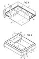
- the second half-shell 2 is, as already mentioned, by injection molding the spring support 21 and the mating contact elements 22 and 23 won, with a cavity for the coil and for the movable armature contact spring unit is free.
- the Mating contact elements each have a close to Outside guided pin 22a or 23a, while in Inside each a fixed contact section 32b or 33b with a Precious metal contact layer 32c or 33c is provided.
- the contact material in the The present example is the contact material as an inlay plated in the surface of the respective contact element, so that a cover when overmoulding easily possible is. Otherwise, other technologies would also apply of the contact material conceivable.
- the two mating contact elements 22 and 23 could of course only be a mating contact element to form an opener or a closer be provided.
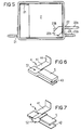
- the L-shaped contact spring 4 has a first Spring leg 41, which extends in front of the coil, and a second spring leg 42, which is laterally extends next to the coil below the armature and one movable contact 43 carries.
- the first spring leg 41 is via an upwardly angled fastening tab 44 the spring support 21 via a welded connection 46 according to FIG 4 or attached via a clamping claw 45 according to FIG. 8. Thanks to this connection technology, the mounting height is Contact spring 4 on the spring support 21 variable, which also the position of the second spring leg 42 relative to the mating contact elements can be adjusted. In this way the anchor restoring force or the rest contact force during the assembly process to compensate for tolerances become.
- the contact spring Before attaching the contact spring to the spring carrier 21 it is connected to the anchor 5, which, for example, according to 6 done electrically conductive via a welded joint 51 can. Should be insulation between the contact spring and the magnet system can be reached, so the connection made by an insulating material sheath 52 according to FIG. 7 become. For certain cases of use, it is also possible to conduct the current to the contact spring via a wire. For example, higher tax levels can be achieved through such Low-resistance wire to the contact point to to avoid excessive heating of the spring.
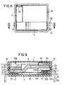
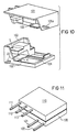
- FIG. 10 shows a variant of the relay from FIG. 1.
- the two half-shells 101 and 102 are not in a single joining plane, but with mutually graduated Joining planes 103 and 104 connected.
- the interior structure of the Relay is the same as in the previous example, except that a mating contact element, namely a normally open mating contact plate 105 with its pin 105a in the first half-shell is injected with the magnet system.
- a mating contact element namely a normally open mating contact plate 105 with its pin 105a in the first half-shell is injected with the magnet system.
- the distance between the two half-shells can be added the counter contacts are influenced.
- the construction of the relay allowed by the application of the relative parts also plan other embodiments of the connection geometry, so that the connections also on only one relay side can emerge from the housing.
- Such an opportunity is shown in Figure 11, with a first half-shell 110 the contact elements with pins 111, 112 and 113 and a second half shell 120 the magnet system with coil pins 121 and 122 carries.
- Such a relay is required only a small footprint for plugging or soldering.
- flat plugs can also be provided.
- the connector pins can of course also designed as surface-mountable SMT connections his.
Landscapes
- Physics & Mathematics (AREA)
- Electromagnetism (AREA)
- Engineering & Computer Science (AREA)
- Manufacturing & Machinery (AREA)
- Electromagnets (AREA)
- Manufacturing Of Electric Cables (AREA)
- Financial Or Insurance-Related Operations Such As Payment And Settlement (AREA)
- General Factory Administration (AREA)
Abstract
Description
Die Erfindung betrifft ein elektromagnetisches Relais mit
- einem ersten Gehäuseteil, der eine Spule sowie einen die Spule durchsetzenden, außerhalb der Spule an deren beiden Enden Polbleche bildenden Kern trägt,
- einem zweiten Gehäuseteil, in welchem mindestens ein Federträger sowie mindestens ein Gegenkontaktelement verankert sind, wobei der Federträger eine mit dem Gegenkontaktelement zusammenwirkende Kontaktfeder trägt, und
- einem Anker, der mit der Kontaktfeder verbunden ist und die Polbleche unter Bildung von Arbeitsluftspalten überbrückt. Außerdem betrifft die Erfindung ein Verfahren zur Herstellung eines solchen Relais.
- a first housing part which carries a coil and a core which passes through the coil and forms pole sheets outside the coil at its two ends,
- a second housing part, in which at least one spring carrier and at least one counter-contact element are anchored, the spring carrier carrying a contact spring which interacts with the counter-contact element, and
- an armature, which is connected to the contact spring and bridges the pole plates with the formation of working air gaps. The invention also relates to a method for producing such a relay.
In der EP 0 531 890 A1 ist ein Schaltrelais beschrieben, welches grundsätzlich einen Aufbau der eingangs genannten Art aufweist. Die beiden Gehäuseteile bilden dort allerdings kein geschlossenes Gehäuse, sondern es handelt sich lediglich um eine Basis, die vorzugsweise eine Leiterplatte mit angeformter Seitenwand ist, und einen Deckelteil, zwischen denen auch nach dem Zusammenfügen ein großer Gehäusespalt offen bleibt. Vorzugsweise ist das dortige Relais als Vielfachrelais mit einer Reihe von nebeneinander liegenden Magnetsystemen ausgebildet, wobei eine gemeinsame Kernpolplatte auf dem Sockel liegt und eine Reihe von senkrecht abstehenden Kernabschnitten bildet, auf die jeweils eine Spule aufgesteckt ist. Jedes System besitzt außerdem einen U-förmigen Anker, der an der Kernpolplatte gelagert ist und mit der Kontaktfeder die Spule rahmenförmig umschließt. Der Deckelteil weist Schlitze mit eingesteckten Gegenkontaktelementen und Federträgern auf, wobei diese Schlitze ebenfalls nicht dicht sind. Eine Justierung der Kontakte erfolgt dort offensichtlich durch die große Gehäuseöffnung im Bereich der Kontakte.EP 0 531 890 A1 describes a switching relay, which basically a structure of the type mentioned having. However, the two housing parts do not form there closed housing, it is just about a base, which is preferably a printed circuit board with molded Is sidewall, and a lid part, between which too after the assembly, a large housing gap remains open. The relay there is preferably a multiple relay a series of magnet systems lying side by side, with a common core pole plate on the base lies and a series of vertically protruding core sections forms, on each of which a coil is attached. Each System also has a U-shaped anchor attached to the Core pole plate is mounted and the coil with the contact spring encloses in a frame shape. The cover part has slots inserted mating contact elements and spring supports, whereby these slots are also not tight. An adjustment the contacts are obviously made by the big one Housing opening in the area of the contacts.
Aus der WO 91/07770 ist bereits ein Relais bekannt, bei dem das Magnetsystem im oberen Bereich eines Gehäuses befestigt ist, während ein Kontaktsystem von der offenen Unterseite her soweit eingeschoben wird, bis bei erregtem Magnetsystem der Kontakt schließt. Nachdem dieses Kontaktsystem zur Erzeugung eines gewünschten Überhubes um einen vorgegebenen Betrag weiter eingeschoben wurde, wird es in dem Gehäuse befestigt. Auf diese Weise werden bereits bei der Montage Fertigungstoleranzen ausgeglichen, so daß eine nachträgliche Justierung nicht mehr erforderlich ist.A relay is already known from WO 91/07770, in which the magnet system is fixed in the upper area of a housing while a contact system is from the open bottom is pushed in until the magnet system is excited Contact closes. After creating this contact system a desired overstroke by a predetermined amount inserted, it is fastened in the housing. On this way, manufacturing tolerances become apparent during assembly balanced, so that a subsequent adjustment is not more is needed.
Aus der DE-A-2 506 626 ist ein mit einem Gehäuse abschließbarer, aus Isolierstoff bestehender Kontaktträger für Schaltelemente bekannt, wobei Ankerkontakte entweder in einem Glasrohr oder in einem Kunststoffrahmen als Träger befestigt sind, wobei diese Träger nach außen durch zwei Gehäusekappen abgeschlossen werden. Alle beweglichen Teile sind dort in ein und demselben Trägerteil gehalten, während die Gehäusekappen keinen Einfluß auf die Positionierung der Funktionselemente des Relais haben.DE-A-2 506 626 describes a lockable with a housing, Contact carrier for switching elements made of insulating material known, anchor contacts either in a glass tube or attached in a plastic frame as a carrier are, these carriers to the outside through two housing caps be completed. All moving parts are in one and the same support part held while the housing caps no influence on the positioning of the functional elements of the relay.
In der EP-A-0 251 035 ist ferner ein Relais beschrieben, welches aus zwei halbschalenförmigen, einen Spulenkörper bildenden Grundkörperteilen besteht, die die Wicklung tragen. In einen der Grundkörperteile sind in einer gemeinsamen Ebene zwei Polbleche eingebettet, deren Enden in einem Kontaktraum innerhalb der Spule durch einen Ankerkontakt überbrückt werden. Der Anker selbst ist über eine rahmenförmige Feder in der Trennebene zwischen den beiden Grundkörperteilen fixiert.EP-A-0 251 035 also describes a relay which of two half-shell-shaped, forming a bobbin Basic body parts exist that carry the winding. In one of the basic body parts are in a common plane two pole plates embedded, the ends of which are in a contact space can be bridged within the coil by an armature contact. The anchor itself is in via a frame-shaped spring the parting plane between the two base parts.
Ziel der vorliegenden Erfindung ist es, ein Relais der eingangs genannten Art mit flachem Aufbau zu schaffen, das für unterschiedliche Größen und Anwendungen konzipiert ist und das bei Anwendung entsprechender Fertigungsverfahren in großen Stückzahlen sehr kostengünstig hergestellt werden kann. Dabei soll aufgrund der Konstruktion eine hohe Genauigkeit bereits in der Fertigung erreicht werden, so daß auch ohne nachträgliche Justierung die Relaiskennwerte mit nur geringen Streuungen eingehalten werden.The aim of the present invention is to provide a relay of the input to create the type mentioned with a flat structure that for different sizes and applications is designed and that when using appropriate manufacturing processes in large Quantity can be produced very inexpensively. Due to the construction, a high level of accuracy is intended can already be achieved in production, so that even without Subsequent adjustment of the relay parameters with only small Scattering are observed.
Erfindungsgemäß wird dieses Ziel bei einem derartigen Relais dadurch erreicht, daß die beiden Gehäuseteile als annähernd wannenförmige Halbschalen aus Kunststoff mit ihren Rändern abdichtend zusammengefügt sind, daß die Anschlüsse für die Spulenwicklung und für die Kontaktelemente jeweils durch die Wand ihres zugehörigen Gehäuseteiles eingebettet nach außen geführt sind, und daß die Haupt-Fügeebenen zwischen beiden Gehäuseteilen senkrecht zur Schaltbewegung der Kontaktfeder stehen.According to the invention, this goal is achieved with such a relay achieved in that the two housing parts as approximately trough-shaped half-shells made of plastic with their edges are sealed together that the connections for the Coil winding and for the contact elements each by the Wall of its associated housing part embedded to the outside are guided, and that the main joining planes between the two Housing parts perpendicular to the switching movement of the contact spring stand.
Bei dem erfindungsgemäßen Relais bilden die beiden Halbschalen nicht nur ein leicht abzudichtendes Gehäuse, sondern sie dienen auch als Träger für die Funktionselemente des Relais, wobei diese Funktionselemente, also das Magnetsystem im einen Teil und das Kontaktsystem in dem anderen Teil bereits bei der Fertigung der jeweiligen Halbschale sehr genau positioniert werden können. Dabei stehen die Haupt-Fügeebenen zwischen beiden Gehäuseteilen senkrecht zur Schaltbewegung der Kontaktfeder, so daß durch das Zusammenfügen der beiden Gehäuseteile der Abstand zwischen Magnetsystem und Kontakten eingestellt werden kann. Besonders einfach werden die Fixierung der Funktionsteile im Gehäuse und die Abdichtung der Anschlüsse dadurch erreicht, daß diese in die jeweilige Gehäuse-Halbschale eingebettet sind. Die Fügeebenen bestehen aus Kunststoff, vorzugsweise thermoplastischem Kunststoff, so daß eine dichte Verbindung, beispielsweise mit Ultraschall, auf einfache Weise zu bewerkstelligen ist.In the relay according to the invention, the two half-shells form not just an easy-to-seal housing, but it also serve as carriers for the functional elements of the relay, these functional elements, i.e. the magnet system in one Part and the contact system in the other part already the manufacture of the respective half-shell positioned very precisely can be. The main joining planes are between two housing parts perpendicular to the switching movement of the Contact spring so that by joining the two housing parts the distance between the magnet system and contacts can be adjusted. Fixation is particularly easy of the functional parts in the housing and the sealing of the connections achieved in that this in the respective housing half-shell are embedded. The joining levels consist of Plastic, preferably thermoplastic, so that a tight connection, for example with ultrasound is easy to do.
In einer bevorzugten Ausführungsform besteht das Magnetsystem aus einem U-förmigen Kern-Jochblech, welches vorzugsweise ebenso wie mindestens zwei Spulenanschlüsse in einen Kunststoff-Spulenkörper eingebettet sind. Die an beiden Enden des Kerns ausgebildeten Polbleche erstrecken sich dann senkrecht zur Spulenachse in den Bereich neben der Spule, wo sie von einem neben der Spule liegenden Anker überbrückt werden. Dieser Anker kann mehr oder weniger als ebenes Blech ausgebildet sein bzw. an beiden Enden in unterschiedliche Höhen abgekröpft sein, um mit entsprechend ebenfalls in der Höhe versetzten Polblechen zusammenzuwirken. Auf diese Weise kann der Raum im Gehäuse für die Unterbringung der Kontakte und der verschiedenen Anschlüsse optimal ausgenutzt werden. Eine L-förmige Kontaktfeder, die sich mit einem Schenkel stirnseitig vor der Spule und mit dem anderen Schenkel neben der Spule unter oder über dem Anker erstreckt, ergibt auf engem Raum eine große Federlänge; der Anker ist vorzugsweise im Übergangsbereich zwischen beiden Federschenkeln an der Kontaktfeder befestigt.In a preferred embodiment there is the magnet system from a U-shaped core yoke sheet, which is preferably as well as at least two coil connections in a plastic coil body are embedded. The on both ends of the Core formed pole plates then extend vertically to the coil axis in the area next to the coil, where it is from an armature lying next to the coil can be bridged. This Anchor can be designed more or less as a flat sheet be bent or bent at different heights at both ends to be offset accordingly in height as well Interacting pole plates. In this way, the Space in the housing for housing the contacts and the various connections can be used optimally. An L-shaped Contact spring, which is front with a leg in front of the coil and with the other leg next to the coil Extending below or above the anchor results in a narrow space a large feather length; the anchor is preferably in the transition area between the two spring legs on the contact spring attached.
Ein bevorzugtes Verfahren zur Herstellung des Relais besteht
darin, daß der erste Gehäuseteil durch erfindungsgemäßen Einbetten
der Spule mit dem Kern einschließlich der Spulenanschlüsse
gewonnen wird,
daß der zweite Gehäuseteil durch Einbetten des Federträgers
und mindestens einen Gegenkontaktelementes gewonnen wird,
daß die mit dem Anker verbundene Kontaktfeder mit dem Federträger
verbunden wird, und
daß dann die beiden Gehäuseteile mit ihren Rändern aufeinandergelegt
und verbunden werden. Vorzugsweise wird dabei auch
der Spulenkörper bereits vorher durch Einbetten des Kerns und
der Spulenanschlüsse gebildet, wobei nach dem Wickeln der
Spule und nach dem Verbinden der Spulenenden mit den Spulenanschlüssen
durch eine zweite Einbettung der erste Gehäuseteil
hergestellt wird. Vor dem Zusammenfügen der beiden Gehäuseteile
wird der Anker mit der Kontaktfeder verbunden, wobei
je nach dem Anwendungsfall eine elektrisch leitende Verbindung
durch Schweißen oder dergleichen oder eine isolierende
Verbindung durch Umspritzen möglich ist. Die Kontaktfeder
wird dann an dem im zweiten Gehäuseteil verankerten Federträger
elektrisch leitend befestigt, beispielsweise durch
Schweißen oder auch über eine Steckbefestigung.A preferred method for producing the relay is that the first housing part is obtained by embedding the coil with the core, including the coil connections, according to the invention.
that the second housing part is obtained by embedding the spring support and at least one counter-contact element, that the contact spring connected to the armature is connected to the spring support, and
that the two housing parts are then placed on top of one another with their edges and connected. Preferably, the coil former is also formed beforehand by embedding the core and the coil connections, with the first housing part being produced by a second embedding after winding the coil and after connecting the coil ends to the coil connections. Before the two housing parts are joined together, the armature is connected to the contact spring, an electrically conductive connection by welding or the like or an insulating connection by overmolding being possible, depending on the application. The contact spring is then attached to the spring support anchored in the second housing part in an electrically conductive manner, for example by welding or also by means of a plug-in fastening.
Ein wesentlicher Vorteil der Erfindung ist auch darin zu sehen, daß beim Fügen der beiden Gehäuseteile der Kontaktüberhub eingestellt werden kann, indem beispielsweise beim Fügen die Durchzugsspannung des Ankers gemessen und dann der Fügevorgang beim Erreichen eines vorgegebenen elektrischen Kennwertes der Durchzugsspannung - der ein Maß für die Abbrandgröße bzw. den Überhub des Kontaktes ist - unterbrochen wird. Anstelle der Verbindung über Ultraschall oder ein sonstiges Schweißverfahren können die beiden Halbschalen aber auch mit anderen Technologien, beispielsweise durch Kleben, Klemmen, Vergießen oder mittels einer im Zweikomponenten-Spritzgießverfahren angespritzten Elostomerdichtung abgedichtet werden.A major advantage of the invention can also be seen in the fact that that when joining the two housing parts, the contact lift can be set, for example, when joining measured the pull-through voltage of the anchor and then the joining process when reaching a predetermined electrical Characteristic value of the pull-through voltage - which is a measure of the erosion size or the overstroke of the contact is interrupted becomes. Instead of the connection via ultrasound or another However, the two half-shells can be welded also with other technologies, for example by gluing, Clamping, casting or using a two-component injection molding process molded elostomer seal sealed become.
Die Erfindung wird nachfolgend an Ausführungsbeispielen anhand
der Zeichnung näher erläutert. Es zeigt
Das in den Figuren 1 bis 5 gezeigte Relais besteht aus einer
ersten Halbschale 1 und einer zweiten Halbschale 2, wobei die
Halbschale 1 durch Umspritzen einer Spule 3 und die zweite
Halbschale durch Umspritzen eines Federträgers 21 sowie zweier
Gegenkontaktelemente 22 und 23 gebildet ist. An dem Federträger
21 ist eine L-förmige Kontaktfeder 4 befestigt, die
ihrerseits einen Anker 5 trägt. Der annähernd Z-förmig abgebogene
Anker 5 bildet mit seinen Enden jeweils Arbeitsluftspalte
mit zwei Polflächen63 und 64 der Polbleche 61 und
62, die Teil eines U-förmigen Kerns 6 sind, wobei aber das
Polblech 62 aus der Kernebene nach oben abgekröpft ist.The relay shown in Figures 1 to 5 consists of a
first half-
Bei der Herstellung wird zunächst die Spule gewonnen, indem
der Mittelabschnitt des Kerns 6 mit thermoplastischem Kunststoff
umspritzt wird, wodurch ein Spulenkörper 31 gebildet
wird. Die Polbleche 61 und 62 werden dabei freigehalten. Außerdem
werden in den Spulenkörper zwei Spulenanschlüsse 32
und 33 mit eingespritzt, und zwar so, daß nicht nur die nach
außen gerichteten Anschlußstifte 32a und 33a, sondern auch
die inneren, zur Kontaktierung der Wicklungsenden bestimmten
Verbindungsflächen 32b und 33b frei von der Einbettung bleiben.
Nach dem Aufbringen einer Spulenwicklung 34 auf den Spulenkörper
werden deren Enden mit den Verbindungsflächen 32b
und 33b verbunden. Die Wicklungsenden werden dabei geschützt
hinter Rippen 35 in Kanälen 36 des Spulenkörpers geführt. Anschließend
wird die gesamte Spule nochmals umspritzt, um so
die erste Halbschale gemäß Figur 3 zu gewinnen. Die Polflächen
63 und 64 der Polbleche 61 und 62 bleiben auch von dieser
Umspritzung frei, während die übrigen Teile, insbesondere
auch die Spulenwicklung 34, in den Kunststoff 11 der ersten
Halbschale 1 eingebettet werden. Die Spulenanschlußstifte 32a
und 33a sind in dieser erneuten Einbettung dicht nach außen
geführt, wo sie gemäß Figur 1 oder Figur 3 nach unten abgewinkelt
oder in nicht dargestellter Weise auch zur Bildung
von SMT-Anschlüssen in eine waagerechte Ebene abgekröpft werden
können.During manufacture, the coil is first obtained by
the middle section of the core 6 with thermoplastic material
is overmolded, whereby a
Die zweite Halbschale 2 wird, wie bereits erwähnt, durch Umspritzen
des Federträgers 21 sowie der Gegenkontaktelemente
22 und 23 gewonnen, wobei ein Hohlraum für die Spule und für
die bewegliche Anker-Kontaktfedereinheit freigespart ist. Die
Gegenkontaktelemente besitzen dabei jeweils einen dicht zur
Außenseite geführten Anschlußstift 22a bzw. 23a, während im
Inneren jeweils ein Festkontaktabschnitt 32b bzw. 33b mit einer
Edelmetall-Kontaktschicht 32c bzw. 33c versehen ist. Im
vorliegenden Beispiel ist das Kontaktmaterial als Inlay in
die Oberfläche des jeweiligen Kontaktelementes hineinplattiert,
so daß eine Abdeckung beim Umspritzen leicht möglich
ist. Ansonsten wären auch andere Technologien zur Aufbringung
des Kontaktmaterials denkbar. Anstelle der zwei Gegenkontaktelemente
22 und 23 könnte natürlich auch nur ein Gegenkontaktelement
zur Bildung eines Öffners oder eines Schließers
vorgesehen werden. The second half-
Die L-förmig gestaltete Kontaktfeder 4 besitzt einen ersten
Federschenkel 41, der sich stirnseitig vor der Spule erstreckt,
sowie einen zweiten Federschenkel 42, der sich seitlich
neben der Spule unterhalb des Ankers erstreckt und einen
beweglichen Kontakt 43 trägt. Der erste Federschenkel 41 ist
über einen nach oben abgewinkelten Befestigungslappen 44 an
dem Federträger 21 über eine Schweißverbindung 46 gemäß Figur
4 oder über eine Klemmkralle 45 gemäß Figur 8 befestigt.
Durch diese Verbindungstechnik ist die Befestigungshöhe der
Kontaktfeder 4 auf dem Federträger 21 variabel, wodurch auch
die Lage des zweiten Federschenkels 42 gegenüber den Gegenkontaktelementen
eingestellt werden kann. Auf diese Weise
kann die Anker-Rückstellkraft bzw. die Ruhekontaktkraft während
des Montagevorgangs zum Ausgleich von Toleranzen beeinflußt
werden.The L-shaped
Vor der Befestigung der Kontaktfeder an dem Federträger 21
wird sie mit dem Anker 5 verbunden, was beispielsweise gemäß
Figur 6 über eine Schweißverbindung 51 elektrisch leitend geschehen
kann. Soll eine Isolierung zwischen der Kontaktfeder
und dem Magnetsystem erreicht werden, so kann die Verbindung
durch eine Isolierstoff-Umhüllung 52 gemäß Figur 7 vorgenommen
werden. Für bestimmte Auswendungsfälle ist es auch möglich,
den Strom zur Kontaktfeder über eine Litze zu führen.
So können beispielsweise höhere Steuerstärken über eine derartige
Litze niederohmig zur Kontaktstelle geführt werden, um
eine zu starke Erwärmung der Feder zu vermeiden.Before attaching the contact spring to the
Beim Zusammenfügen der beiden Halbschalen 1 und 2 (siehe Figur
9) greift eine Umfangswand 12 schachtelförmig über den
unteren Gehäuseteil 2, der zu diesem Zweck einen innen umlaufenden
Steg 24 aufweist. Um eine genaue Justierung der Abstände
zwischen Magnetsystem und Kontaktsystem zu erreichen,
besitzt einer der Gehäuseteile außerdem eine umlaufende Rippe
25, die während des Fügens mittels Ultraschall deformiert
wird und die dichte Verbindung zwischen beiden Halbschalen
herstellt. Beim Fügen der beiden Halbschalen wird dabei die
Durchzugsspannung des Ankers gemessen, wobei der Anker an die
Polflächen 63 und 64 der Polbleche 61 und 62 angezogen wird.
Sobald ein vorgegebener Kennwert der Durchzugsspannung als
Maß für die Abbrandgröße bzw. den Überhub des Kontaktes erreicht
ist, wird der Fügevorgang beendet. Das Relais ist damit
justiert und zugleich abgedichtet.When joining the two
In Figur 10 ist eine Variante des Relais von Figur 1 gezeigt.
In diesem Fall sind die beiden Halbschalen 101 und 102 nicht
in einer einzigen Fügeebene, sondern mit gegeneinander abgestuften
Fügeebenen 103 und 104 verbunden. Der Innenaufbau des
Relais ist der gleiche wie im vorherigen Beispiel, abgesehen
davon, daß ein Gegenkontaktelement, nämlich ein Schließer-Gegenkontaktblech
105 mit seinem Anschlußstift 105a in die
erste Halbschale mit dem Magnetsystem eingespritzt ist. Beim
Fügen der beiden Halbschalen kann in diesem Fall der Abstand
der Gegenkontakte beeinflußt werden. Bei dieser Variante können
durch eine schieberlose Spritzgießform sowohl Schweiß-,
Niet- als auch Inlay-Kontakte an den Gegenkontaktelementen
vorgesehen werden.FIG. 10 shows a variant of the relay from FIG. 1.
In this case, the two half-
Der Aufbau des Relais gestattet durch die Anwendung der relativ
planen Teile auch andere Ausführungsformen der Anschlußgeometrie,
so daß die Anschlüsse auch auf nur einer Relaisseite
aus dem Gehäuse austreten können. Eine solche Möglichkeit
ist in Figur 11 gezeigt, wobei eine erste Halbschale
110 die Kontaktelemente mit Anschlußstiften 111, 112 und 113
und eine zweite Halbschale 120 das Magnetsystem mit Spulenanschlußstiften
121 und 122 trägt. Ein solches Relais benötigt
zum Stecken oder zum Löten nur eine kleine Grundfläche. Anstelle
der in Figur 11 gezeigten Lötanschlußstifte könnten
natürlich auch Flachstecker vorgesehen werden. Wie bereits
früher erwähnt wurde, können die Anschlußstifte natürlich
auch als oberflächenmontierbare SMT-Anschlüsse ausgeführt
sein.The construction of the relay allowed by the application of the relative
parts also plan other embodiments of the connection geometry,
so that the connections also on only one relay side
can emerge from the housing. Such an opportunity
is shown in Figure 11, with a first half-
Claims (20)
- Electromagnetic relay havingcharacterizeda first housing part (1), which is fitted with a coil (3) as well as a core (6) which passes through the coil and, outside the coil, forms pole plates (61, 62) at its two ends,a second housing part (2) in which at least one spring support (21) and at least one mating contact element (22, 23) are anchored, the spring support (21) being fitted with a contact spring (4) which interacts with the mating contact element (22, 23), andan armature (5) which is connected to the contact spring (4) and bridges the pole plates (61, 62) forming air gaps,
in that the two housing parts (1, 2) are joined together at their edges, forming a seal, as roughly trough-shaped half-shells made of plastic, while the connections (21a, 22a, 23a, 32a, 33a) for the coil winding (34) and for the contact elements (21, 22, 23) are each passed out through the wall of their respective housing parts (1, 2), and in that the main joint planes between the two housing parts (1, 2) are at right angles to the switching movement of the contact spring (4). - Relay according to Claim 1, characterized in that the coil (3) which is formed from a coil former (31) with a winding (34) is embedded together with the core (6) in the plastic of the first housing part (1), leaving free pole surfaces (63, 64) in the region of the air gaps, while the spring support (21) and the at least one mating contact element (22, 23) are embedded in the plastic of the second housing part (2).
- Relay according to Claim 2,
characterized in that the core (6) is embedded in the plastic of the coil former (31). - Relay according to Claim 3,
characterized in that connecting elements (32, 33) for the coil winding (34) are embedded both in the coil former (31) and in the plastic of the first housing part (1). - Relay according to one of Claims 1 to 4,
characterized in that the core (6) is U-shaped, a centre section being fitted with the coil (3), and two pole plates (61, 62) projecting essentially at right angles to the coil axis, and in that the armature (5) extends essentially parallel to the coil axis alongside the coil (3) and forms the air gaps with the two pole plates (61, 62). - Relay according to Claim 5,
characterized in that the contact spring (4) is cut in an L-shape, so that it has two limbs (41, 42) which essentially run in one plane, of which the first extends at the end in front of the coil, and the second extends at the side alongside the coil, this second limb (42) and the armature (5) being located parallel one above the other and being connected in the corner region between the two limbs of the contact spring. - Relay according to Claim 6,
characterized in that the armature (5) is metallically connected to the contact spring (4), namely by means of welding (51), riveting or the like. - Relay according to Claim 6,
characterized in that the armature (5) is connected to the contact spring (4) via a common dielectric sheath (52). - Relay according to one of Claims 1 to 8,
characterized in that two mating contact elements (22, 23) are anchored in the second housing part (2) and form a changeover contact with the contact spring (4). - Relay according to one of Claims 1 to 8,
characterized in that a second mating contact element (105) is anchored in the first housing part (101) and forms a changeover contact with the mating contact element (23), which is anchored in the second housing part (102), and with the contact spring (4). - Relay according to one of Claims 1 to 10,
characterized in that the two housing parts (1, 2) have edges (103, 104) which are designed to be stepped in at least two mutually parallel offset separating planes. - Method for producing a relay according to Claim 1, in whichcharacterized,a first housing part (1) has anchored in it a coil (3) as well as a core (6) which passes through the coil and, outside the coil, forms pole plates (61, 62) at its two ends,a second housing part (2) has anchored in it at least one spring support (21) and at least one mating contact element (22, 23), the spring support (21) being fitted with a contact spring (4) which interacts with the mating contact element (22, 23), and in whichan armature (5) is connected to the contact spring (4) and bridges the pole plates (61, 62) forming air gaps,the two housing parts (1, 2) each being formed like troughs such that their edges form at least one main joint plane which is at right angles to the movement direction of the armature,in that the first housing part (1) is produced by embedding the coil (3) with the core (6) including the coil connections (32, 33),in that the second housing part (2) is produced by embedding the spring support (21) and at least one mating contact element (22, 23),such that the contact spring (4) which is connected to the armature (5) is connected to the spring support (21), andsuch that the edges of the two housing parts (1, 2) then rest on one another and are connected.
- Method according to Claim 12,
characterized in that a coil former (31) is formed first of all by embedding the core (6) and the coil connections (32, 33), in that this coil former (31) is provided with a coil winding (34) and is then embedded once again in order to form the first housing part (1). - Method according to Claim 12 or 13,
characterized in that the armature (5) is connected to the contact spring (4) by welding, and the latter is then connected to the spring support (21). - Method according to Claim 12 or 13,
characterized in that the armature (5) is connected to the contact spring (4) by being embedded in dielectric (52). - Relay according to one of Claims 12 to 15,
characterized in that the contact spring (4) is connected to the spring support (21) by welding. - Relay according to one of Claims 12 to 15,
characterized in that the contact spring (4) is connected to the spring support (21) by plug-in attachment. - Method according to one of Claims 12 to 17,
characterized in that, when the two housing parts (1, 2) are being joined together, the armature travel and/or the overtravel are measured indirectly (electrically via the seal-in voltage) and the joining process is ended when a predetermined magnitude is reached. - Method according to Claim 18,
characterized in that the edge region (25) of at least one of the two half-shells (1) is deformed during the joining process until the predetermined overtravel is reached. - Method according to Claim 19,
characterized in that the edge or a rib (25), which is integrally formed on the edge, of one of the two half-shells (1) is deformed by ultrasound during the joining process.
Applications Claiming Priority (3)
| Application Number | Priority Date | Filing Date | Title |
|---|---|---|---|
| DE19627844A DE19627844C1 (en) | 1996-07-10 | 1996-07-10 | Plastics-moulded electromagnetic relay with mfg. method |
| DE19627844 | 1996-07-10 | ||
| PCT/DE1997/001230 WO1998001880A1 (en) | 1996-07-10 | 1997-06-17 | Electromagnetic relay and process for producing the same |
Publications (2)
| Publication Number | Publication Date |
|---|---|
| EP0914665A1 EP0914665A1 (en) | 1999-05-12 |
| EP0914665B1 true EP0914665B1 (en) | 2000-01-26 |
Family
ID=7799471
Family Applications (1)
| Application Number | Title | Priority Date | Filing Date |
|---|---|---|---|
| EP97931621A Expired - Lifetime EP0914665B1 (en) | 1996-07-10 | 1997-06-17 | Electromagnetic relay and process for producing the same |
Country Status (7)
| Country | Link |
|---|---|
| US (1) | US6252479B1 (en) |
| EP (1) | EP0914665B1 (en) |
| JP (1) | JP2000514235A (en) |
| KR (1) | KR20000023651A (en) |
| AT (1) | ATE189334T1 (en) |
| DE (2) | DE19627844C1 (en) |
| WO (1) | WO1998001880A1 (en) |
Cited By (1)
| Publication number | Priority date | Publication date | Assignee | Title |
|---|---|---|---|---|
| ES2155383A1 (en) * | 1998-05-07 | 2001-05-01 | Siemens Electromech Components | Magnet device for electromagnetic relay |
Families Citing this family (9)
| Publication number | Priority date | Publication date | Assignee | Title |
|---|---|---|---|---|
| CN1169177C (en) * | 1998-07-27 | 2004-09-29 | 西门子公司 | Switching device with housing bottom as a sub-assembly and corresponding production method |
| DE10209810B4 (en) * | 2001-03-09 | 2006-11-16 | Omron Corporation | relay |
| GB0110948D0 (en) * | 2001-05-04 | 2001-06-27 | Tyco Electronics Amp Gmbh | Bus controlled relays |
| JP4022440B2 (en) * | 2002-07-01 | 2007-12-19 | 株式会社オートネットワーク技術研究所 | Circuit unit |
| KR101014987B1 (en) * | 2002-11-15 | 2011-02-16 | 타이코 일렉트로닉스 에이엠피 게엠베하 | Magnet system extrusion coating for a relay |
| WO2004094448A1 (en) * | 2003-04-23 | 2004-11-04 | Taisho Pharmaceutical Co. Ltd. | METHYLATED CpG POLYNUCLEOTIDE |
| DE102012003236A1 (en) | 2012-02-20 | 2013-08-22 | Clariant Produkte (Deutschland) Gmbh | Gold plating of Pd-Au coated shell catalysts |
| CN110473743B (en) * | 2019-04-25 | 2024-06-18 | 厦门宏发汽车电子有限公司 | Relay capable of ensuring normal action of armature or movable spring |
| EP4002414A1 (en) * | 2020-11-13 | 2022-05-25 | Tyco Electronics Austria GmbH | Electric device comprising a sealed housing having a lower housing part and an upper housing part |
Family Cites Families (14)
| Publication number | Priority date | Publication date | Assignee | Title |
|---|---|---|---|---|
| FR1598789A (en) | 1968-12-27 | 1970-07-06 | ||
| BE786042A (en) | 1970-12-02 | 1973-01-10 | Int Standard Electric Corp | MULTIPOLAR CONTACT EQUIPMENT PLACED IN A SEALED ENCLOSURE |
| DE2506626A1 (en) | 1975-02-17 | 1976-08-26 | Hans Sauer | WITH A LOCKABLE HOUSING, MADE OF INSULATING MATERIAL, FOR SWITCHING ELEMENTS |
| DE2622133A1 (en) | 1976-05-18 | 1977-12-08 | Siemens Ag | ELECTRICAL COMPONENT, IN PARTICULAR ELECTROMAGNETIC RELAY |
| DE2723430C2 (en) * | 1977-05-24 | 1984-04-26 | Siemens AG, 1000 Berlin und 8000 München | Electromagnetic relay |
| DE3378805D1 (en) | 1982-07-06 | 1989-02-02 | Nec Corp | Transfer-type electromagnetic relay |
| US4827234A (en) | 1986-06-23 | 1989-05-02 | Siemens Aktiengesellschaft | Electromagnetic relay |
| US4975666A (en) * | 1989-03-28 | 1990-12-04 | Matsushita Electric Works, Ltd. | Polarized electromagnetic relay |
| ATE95947T1 (en) * | 1989-11-16 | 1993-10-15 | Siemens Ag | ELECTROMAGNETIC RELAY. |
| EP0501951B1 (en) | 1989-11-16 | 1993-10-13 | Siemens Aktiengesellschaft | Electromagnetic relay |
| US5038123A (en) * | 1989-12-14 | 1991-08-06 | General Motors Corporation | Flat electromagnetic relay |
| US5191306A (en) * | 1990-09-14 | 1993-03-02 | Matsushita Electric Works, Ltd. | Miniature electromagnetic assembly and relay with the miniature electromagnet assembly |
| US5148136A (en) * | 1991-08-19 | 1992-09-15 | General Motors Corporation | Flat electromagnetic relay |
| US5216396A (en) * | 1991-09-13 | 1993-06-01 | Eaton Corporation | Switching relay |
-
1996
- 1996-07-10 DE DE19627844A patent/DE19627844C1/en not_active Expired - Fee Related
-
1997
- 1997-06-17 EP EP97931621A patent/EP0914665B1/en not_active Expired - Lifetime
- 1997-06-17 US US09/214,731 patent/US6252479B1/en not_active Expired - Fee Related
- 1997-06-17 AT AT97931621T patent/ATE189334T1/en not_active IP Right Cessation
- 1997-06-17 WO PCT/DE1997/001230 patent/WO1998001880A1/en not_active Application Discontinuation
- 1997-06-17 JP JP10504638A patent/JP2000514235A/en active Pending
- 1997-06-17 DE DE59701074T patent/DE59701074D1/en not_active Expired - Lifetime
-
1999
- 1999-01-08 KR KR1019997000104A patent/KR20000023651A/en not_active Application Discontinuation
Cited By (1)
| Publication number | Priority date | Publication date | Assignee | Title |
|---|---|---|---|---|
| ES2155383A1 (en) * | 1998-05-07 | 2001-05-01 | Siemens Electromech Components | Magnet device for electromagnetic relay |
Also Published As
| Publication number | Publication date |
|---|---|
| WO1998001880A1 (en) | 1998-01-15 |
| JP2000514235A (en) | 2000-10-24 |
| US6252479B1 (en) | 2001-06-26 |
| ATE189334T1 (en) | 2000-02-15 |
| DE19627844C1 (en) | 1997-08-28 |
| DE59701074D1 (en) | 2000-03-02 |
| EP0914665A1 (en) | 1999-05-12 |
| KR20000023651A (en) | 2000-04-25 |
Similar Documents
| Publication | Publication Date | Title |
|---|---|---|
| DE60018502T2 (en) | Electromagnetic relay | |
| DE19747167C1 (en) | Electromagnetic relay e.g. for high-load currents | |
| DE4406682A1 (en) | Magnet coil, magnetic contactor with a magnet coil, and a manufacturing method for a magnet coil | |
| EP0914665B1 (en) | Electromagnetic relay and process for producing the same | |
| DE3829035C2 (en) | ||
| EP1025573B1 (en) | Method for producing a relay | |
| EP0017129B2 (en) | Polarised relay having contact blades | |
| EP0758484B1 (en) | Modular relay | |
| DE69735239T2 (en) | HIGH FREQUENCY SWITCH | |
| EP0713233A2 (en) | Arrangement of a relay with a plug-in adapter and method of manufacturing this arrangement | |
| DE2353444A1 (en) | Electromagnetic relay embedded in insulating material - is surrounded by housing cap with base plate affording injection of insulating material | |
| DE4310369A1 (en) | adapter | |
| EP0308819B1 (en) | Electromagnetic relay | |
| EP0910861B1 (en) | Process for manufacturing an electromagnetic relay | |
| EP0056085B1 (en) | Polarised electromagnetic relay | |
| EP0858670A2 (en) | Electric contact switch | |
| DE3435823C2 (en) | Process for the production of jack plugs | |
| EP0846330B1 (en) | Electromagnetic relay and its use on a printed circuit board | |
| DE3025814A1 (en) | ELECTROMAGNETIC RELAY | |
| DE10304445A1 (en) | Connection structure of a high-frequency transmission part | |
| EP0410984B1 (en) | Spool body and process for producing a spool body | |
| EP0502842B1 (en) | Electromagnetic relay | |
| EP0056840B1 (en) | Electromagnetic relay | |
| DE19511877A1 (en) | Contact unit, especially for electrical switches | |
| DE19820458C1 (en) | Magnetic system for electromagnetic relay |
Legal Events
| Date | Code | Title | Description |
|---|---|---|---|
| PUAI | Public reference made under article 153(3) epc to a published international application that has entered the european phase |
Free format text: ORIGINAL CODE: 0009012 |
|
| 17P | Request for examination filed |
Effective date: 19990105 |
|
| AK | Designated contracting states |
Kind code of ref document: A1 Designated state(s): AT CH DE FR GB IT LI |
|
| GRAG | Despatch of communication of intention to grant |
Free format text: ORIGINAL CODE: EPIDOS AGRA |
|
| GRAG | Despatch of communication of intention to grant |
Free format text: ORIGINAL CODE: EPIDOS AGRA |
|
| GRAH | Despatch of communication of intention to grant a patent |
Free format text: ORIGINAL CODE: EPIDOS IGRA |
|
| 17Q | First examination report despatched |
Effective date: 19990623 |
|
| GRAH | Despatch of communication of intention to grant a patent |
Free format text: ORIGINAL CODE: EPIDOS IGRA |
|
| GRAA | (expected) grant |
Free format text: ORIGINAL CODE: 0009210 |
|
| AK | Designated contracting states |
Kind code of ref document: B1 Designated state(s): AT CH DE FR GB IT LI |
|
| REF | Corresponds to: |
Ref document number: 189334 Country of ref document: AT Date of ref document: 20000215 Kind code of ref document: T |
|
| REG | Reference to a national code |
Ref country code: CH Ref legal event code: EP |
|
| REF | Corresponds to: |
Ref document number: 59701074 Country of ref document: DE Date of ref document: 20000302 |
|
| ITF | It: translation for a ep patent filed | ||
| ET | Fr: translation filed | ||
| GBT | Gb: translation of ep patent filed (gb section 77(6)(a)/1977) |
Effective date: 20000330 |
|
| PG25 | Lapsed in a contracting state [announced via postgrant information from national office to epo] |
Ref country code: AT Free format text: LAPSE BECAUSE OF NON-PAYMENT OF DUE FEES Effective date: 20000617 |
|
| PLBE | No opposition filed within time limit |
Free format text: ORIGINAL CODE: 0009261 |
|
| STAA | Information on the status of an ep patent application or granted ep patent |
Free format text: STATUS: NO OPPOSITION FILED WITHIN TIME LIMIT |
|
| 26N | No opposition filed | ||
| REG | Reference to a national code |
Ref country code: GB Ref legal event code: 732E |
|
| PGFP | Annual fee paid to national office [announced via postgrant information from national office to epo] |
Ref country code: GB Payment date: 20010502 Year of fee payment: 5 |
|
| PGFP | Annual fee paid to national office [announced via postgrant information from national office to epo] |
Ref country code: FR Payment date: 20010531 Year of fee payment: 5 |
|
| PG25 | Lapsed in a contracting state [announced via postgrant information from national office to epo] |
Ref country code: LI Free format text: LAPSE BECAUSE OF NON-PAYMENT OF DUE FEES Effective date: 20010630 Ref country code: CH Free format text: LAPSE BECAUSE OF NON-PAYMENT OF DUE FEES Effective date: 20010630 |
|
| REG | Reference to a national code |
Ref country code: GB Ref legal event code: IF02 |
|
| REG | Reference to a national code |
Ref country code: CH Ref legal event code: PL |
|
| PG25 | Lapsed in a contracting state [announced via postgrant information from national office to epo] |
Ref country code: GB Free format text: LAPSE BECAUSE OF NON-PAYMENT OF DUE FEES Effective date: 20020617 |
|
| GBPC | Gb: european patent ceased through non-payment of renewal fee |
Effective date: 20020617 |
|
| PG25 | Lapsed in a contracting state [announced via postgrant information from national office to epo] |
Ref country code: FR Free format text: LAPSE BECAUSE OF NON-PAYMENT OF DUE FEES Effective date: 20030228 |
|
| REG | Reference to a national code |
Ref country code: FR Ref legal event code: ST |
|
| PG25 | Lapsed in a contracting state [announced via postgrant information from national office to epo] |
Ref country code: IT Free format text: LAPSE BECAUSE OF NON-PAYMENT OF DUE FEES;WARNING: LAPSES OF ITALIAN PATENTS WITH EFFECTIVE DATE BEFORE 2007 MAY HAVE OCCURRED AT ANY TIME BEFORE 2007. THE CORRECT EFFECTIVE DATE MAY BE DIFFERENT FROM THE ONE RECORDED. Effective date: 20050617 |
|
| PGFP | Annual fee paid to national office [announced via postgrant information from national office to epo] |
Ref country code: DE Payment date: 20140627 Year of fee payment: 18 |
|
| REG | Reference to a national code |
Ref country code: DE Ref legal event code: R119 Ref document number: 59701074 Country of ref document: DE |
|
| PG25 | Lapsed in a contracting state [announced via postgrant information from national office to epo] |
Ref country code: DE Free format text: LAPSE BECAUSE OF NON-PAYMENT OF DUE FEES Effective date: 20160101 |