EP0912251B1 - A dispensing device and method for forming material - Google Patents
A dispensing device and method for forming material Download PDFInfo
- Publication number
- EP0912251B1 EP0912251B1 EP97932918A EP97932918A EP0912251B1 EP 0912251 B1 EP0912251 B1 EP 0912251B1 EP 97932918 A EP97932918 A EP 97932918A EP 97932918 A EP97932918 A EP 97932918A EP 0912251 B1 EP0912251 B1 EP 0912251B1
- Authority
- EP
- European Patent Office
- Prior art keywords
- liquid
- liquids
- fibre
- matter
- outlet
- Prior art date
- Legal status (The legal status is an assumption and is not a legal conclusion. Google has not performed a legal analysis and makes no representation as to the accuracy of the status listed.)
- Expired - Lifetime
Links
Images


Classifications
-
- D—TEXTILES; PAPER
- D01—NATURAL OR MAN-MADE THREADS OR FIBRES; SPINNING
- D01D—MECHANICAL METHODS OR APPARATUS IN THE MANUFACTURE OF ARTIFICIAL FILAMENTS, THREADS, FIBRES, BRISTLES OR RIBBONS
- D01D5/00—Formation of filaments, threads, or the like
- D01D5/0007—Electro-spinning
- D01D5/0061—Electro-spinning characterised by the electro-spinning apparatus
- D01D5/0076—Electro-spinning characterised by the electro-spinning apparatus characterised by the collecting device, e.g. drum, wheel, endless belt, plate or grid
- D01D5/0084—Coating by electro-spinning, i.e. the electro-spun fibres are not removed from the collecting device but remain integral with it, e.g. coating of prostheses
-
- A—HUMAN NECESSITIES
- A61—MEDICAL OR VETERINARY SCIENCE; HYGIENE
- A61L—METHODS OR APPARATUS FOR STERILISING MATERIALS OR OBJECTS IN GENERAL; DISINFECTION, STERILISATION OR DEODORISATION OF AIR; CHEMICAL ASPECTS OF BANDAGES, DRESSINGS, ABSORBENT PADS OR SURGICAL ARTICLES; MATERIALS FOR BANDAGES, DRESSINGS, ABSORBENT PADS OR SURGICAL ARTICLES
- A61L26/00—Chemical aspects of, or use of materials for, wound dressings or bandages in liquid, gel or powder form
- A61L26/0009—Chemical aspects of, or use of materials for, wound dressings or bandages in liquid, gel or powder form containing macromolecular materials
- A61L26/0028—Polypeptides; Proteins; Degradation products thereof
-
- A—HUMAN NECESSITIES
- A61—MEDICAL OR VETERINARY SCIENCE; HYGIENE
- A61L—METHODS OR APPARATUS FOR STERILISING MATERIALS OR OBJECTS IN GENERAL; DISINFECTION, STERILISATION OR DEODORISATION OF AIR; CHEMICAL ASPECTS OF BANDAGES, DRESSINGS, ABSORBENT PADS OR SURGICAL ARTICLES; MATERIALS FOR BANDAGES, DRESSINGS, ABSORBENT PADS OR SURGICAL ARTICLES
- A61L26/00—Chemical aspects of, or use of materials for, wound dressings or bandages in liquid, gel or powder form
- A61L26/0061—Use of materials characterised by their function or physical properties
- A61L26/0076—Sprayable compositions
-
- A—HUMAN NECESSITIES
- A61—MEDICAL OR VETERINARY SCIENCE; HYGIENE
- A61M—DEVICES FOR INTRODUCING MEDIA INTO, OR ONTO, THE BODY; DEVICES FOR TRANSDUCING BODY MEDIA OR FOR TAKING MEDIA FROM THE BODY; DEVICES FOR PRODUCING OR ENDING SLEEP OR STUPOR
- A61M11/00—Sprayers or atomisers specially adapted for therapeutic purposes
- A61M11/001—Particle size control
-
- A—HUMAN NECESSITIES
- A61—MEDICAL OR VETERINARY SCIENCE; HYGIENE
- A61M—DEVICES FOR INTRODUCING MEDIA INTO, OR ONTO, THE BODY; DEVICES FOR TRANSDUCING BODY MEDIA OR FOR TAKING MEDIA FROM THE BODY; DEVICES FOR PRODUCING OR ENDING SLEEP OR STUPOR
- A61M15/00—Inhalators
- A61M15/02—Inhalators with activated or ionised fluids, e.g. electrohydrodynamic [EHD] or electrostatic devices; Ozone-inhalators with radioactive tagged particles
-
- A—HUMAN NECESSITIES
- A61—MEDICAL OR VETERINARY SCIENCE; HYGIENE
- A61P—SPECIFIC THERAPEUTIC ACTIVITY OF CHEMICAL COMPOUNDS OR MEDICINAL PREPARATIONS
- A61P17/00—Drugs for dermatological disorders
- A61P17/02—Drugs for dermatological disorders for treating wounds, ulcers, burns, scars, keloids, or the like
-
- B—PERFORMING OPERATIONS; TRANSPORTING
- B05—SPRAYING OR ATOMISING IN GENERAL; APPLYING FLUENT MATERIALS TO SURFACES, IN GENERAL
- B05B—SPRAYING APPARATUS; ATOMISING APPARATUS; NOZZLES
- B05B5/00—Electrostatic spraying apparatus; Spraying apparatus with means for charging the spray electrically; Apparatus for spraying liquids or other fluent materials by other electric means
- B05B5/025—Discharge apparatus, e.g. electrostatic spray guns
- B05B5/0255—Discharge apparatus, e.g. electrostatic spray guns spraying and depositing by electrostatic forces only
-
- D—TEXTILES; PAPER
- D01—NATURAL OR MAN-MADE THREADS OR FIBRES; SPINNING
- D01D—MECHANICAL METHODS OR APPARATUS IN THE MANUFACTURE OF ARTIFICIAL FILAMENTS, THREADS, FIBRES, BRISTLES OR RIBBONS
- D01D5/00—Formation of filaments, threads, or the like
- D01D5/0007—Electro-spinning
- D01D5/0061—Electro-spinning characterised by the electro-spinning apparatus
- D01D5/0069—Electro-spinning characterised by the electro-spinning apparatus characterised by the spinning section, e.g. capillary tube, protrusion or pin
-
- D—TEXTILES; PAPER
- D01—NATURAL OR MAN-MADE THREADS OR FIBRES; SPINNING
- D01D—MECHANICAL METHODS OR APPARATUS IN THE MANUFACTURE OF ARTIFICIAL FILAMENTS, THREADS, FIBRES, BRISTLES OR RIBBONS
- D01D5/00—Formation of filaments, threads, or the like
- D01D5/28—Formation of filaments, threads, or the like while mixing different spinning solutions or melts during the spinning operation; Spinnerette packs therefor
- D01D5/30—Conjugate filaments; Spinnerette packs therefor
- D01D5/34—Core-skin structure; Spinnerette packs therefor
-
- D—TEXTILES; PAPER
- D06—TREATMENT OF TEXTILES OR THE LIKE; LAUNDERING; FLEXIBLE MATERIALS NOT OTHERWISE PROVIDED FOR
- D06M—TREATMENT, NOT PROVIDED FOR ELSEWHERE IN CLASS D06, OF FIBRES, THREADS, YARNS, FABRICS, FEATHERS OR FIBROUS GOODS MADE FROM SUCH MATERIALS
- D06M23/00—Treatment of fibres, threads, yarns, fabrics or fibrous goods made from such materials, characterised by the process
-
- B—PERFORMING OPERATIONS; TRANSPORTING
- B05—SPRAYING OR ATOMISING IN GENERAL; APPLYING FLUENT MATERIALS TO SURFACES, IN GENERAL
- B05B—SPRAYING APPARATUS; ATOMISING APPARATUS; NOZZLES
- B05B1/00—Nozzles, spray heads or other outlets, with or without auxiliary devices such as valves, heating means
- B05B1/02—Nozzles, spray heads or other outlets, with or without auxiliary devices such as valves, heating means designed to produce a jet, spray, or other discharge of particular shape or nature, e.g. in single drops, or having an outlet of particular shape
- B05B1/04—Nozzles, spray heads or other outlets, with or without auxiliary devices such as valves, heating means designed to produce a jet, spray, or other discharge of particular shape or nature, e.g. in single drops, or having an outlet of particular shape in flat form, e.g. fan-like, sheet-like
- B05B1/042—Outlets having two planes of symmetry perpendicular to each other, one of them defining the plane of the jet
Definitions
- This invention relates to methods and devices for forming material.
- this invention relates to methods and devices for applying material to a surface, for example to an internal or external surface of an animal, for example for applying material to skin for use, for example, in the care or treatment of wounds or burns.
- aerosol devices for allowing material to be sprayed onto a surface such as the human skin
- aerosol devices for spraying wound care products onto wounds or burns are known, including aerosol devices for spraying wound care products onto wounds or burns.
- One such product is Savlon Dry (trade mark) which has been marketed in the UK by Zyma Healthcare and Ciba Geigy plc.
- Savlon Dry (trade mark) which has been marketed in the UK by Zyma Healthcare and Ciba Geigy plc.
- gas propellant In recent years the choice of gas propellants has become more limited because of the desire to avoid environmentally unfriendly compounds such as a chlorofluorocarbons or hydrocarbons.
- gas propelled sprays are generally designed to spray relatively large droplets or powder particles in order to achieve sufficient inertia to deposit the spray on its target surface.
- gas propelled products may run if sprayed too freely, especially where the spray produces large droplets.
- packaging costs for such devices are high.
- GB-A-1569707 describes a dispensing device for producing a spray or cloud of liquid droplets intended primarily for crop spraying.
- the process described in GB-A-1569707 produces liquid droplets by applying an electric field to a liquid emerging from an outlet in the vicinity of the surface so that the liquid becomes sufficiently charged that the net electric charge in the liquid as the liquid emerges into free space counteracts the surface tension forces of the liquid and the repulsive forces generated by the like electrical charges cause the liquid to be comminuted to produce a cone or jet which breaks into liquid droplets.
- the droplets produced by this device are charged close to their Rayleigh Limit and thus in use migrate quickly toward conductive surfaces of lower or zero potential.
- This technique of comminuting liquid is generally known as electrohydrodynamic comminution or processing.
- RU-A-2 034 534 discloses a method and device for electrohydrodynamically comminuting and applying to the skin a protective cooling consisting of an aseptic solution containing a fibre forming polymer.
- the present invention provides a method of forming composite matter, which comprises supplying a liquid to a first outlet and supplying a further liquid to a second outlet located adjacent the first outlet and subjecting the liquids to an electric field so as to form at least one jet, the liquids being such that, after formation, the jet forms composite matter comprising at least one of a fibre, fibre fragments and particles, the composite matter having a core formed substantially by one of the two liquids and a coating formed substantially by the other of the two liquids.
- the present invention provides a device comprising a housing (9) containing:
- the matter is at least partially electrically discharged before application or supply.
- the deposition process may be repeated one or more times to provide a number of layers of material comprising at least one of fibres, fibrils, droplets or particles on the surface.
- the polarity to which the material is charged may be reversed between deposition of different layers so as facilitate attraction between the layers.
- the liquid used to produce the electrohydrodynamically formed matter may comprise a biologically active ingredient or component.
- the electrohydrodynamically formed material comprises fibrils
- the fibrils may actually stick into the skin of soft tissue enabling delivery of the active component to a location beneath the outer layer of skin or soft tissue.
- the liquid(s) used may comprise a solution, suspension, microsuspension, emulsion, microemulsion, gel or even a melt which may contain an active component or components.
- Microcapsules, fibres or fibrils of a bioresorbable or biodegradable polymer may be formed which contain a biologically active ingredient. Material from the core of fibre or fibril may be released from the ends of the fibre or fibril.
- Material from the core of a fibre, fibril or microcapsule may be released through the coating if the coating is permeable to the material contained within it or may be released as a result of the outer coating being breached, for example by chemical or enzymic attack which causes the outer coating to dissolve or degrade, by bioresorption or biodegradation of the coating, or as a result of temperature changes or application of pressure which causes the outer coating to rupture.
- the timing of the release may be controlled, for a given polymer, by controlling the thickness of the coating surrounding the core.
- Possible biologically active components for topical application are pharmaceutical compounds such as analgesics, antiseptics, antibiotics, antifungals, antibacterials, antiparasitics, debridement agents such as proteolytic enzymes, biological products such as cells, and cytokines for stimulating cytokinetic activity to promote essential cell activities, for example, to stimulate dendritic growth, growth factors such as fibroblast growth factor (FGF), epithelial growth factor (EGF), transforming growth factor (TGF) and others that may be used to promote or otherwise control the sequence of events essential to natural tissue repair, DNA or other genetic material for gene therapy, cells, peptides or polypeptides, insulin, adjuvants, immune suppressants or stimulants, surface binding or surface recognising agents such as surface protein A, and surfactants. Where more than one layer of fibres, fibrils or droplets is deposited, then different active ingredients may be provided in different layers.
- FGF fibroblast growth factor
- EGF epithelial growth factor
- TGF transforming growth factor
- Fibres, fibre fragments or particles of biological material such as fibrin or collagen may be formed using a method embodying the invention. Also electret polymers may be used to act as nuclei or otherwise initiate interactive cellular and/or molecular events in tissue repair.
- a number of electrohydrodynamic processing sites may be provided enabling different types of electrohydrodynamically formed matter to be deposited at the same time.
- the deposited material may be used alone or in combination with a conventional bandage or dressing.
- the material may be deposited onto a conventional dressing to be applied to the skin.
- the fibrils or particles may comprise biologically active material, for example the fibrils or particles may comprise DNA encapsulated in or complexed with a lipid for transfecting cells or may, for example, contain or encapsulate matter such as peptides, polypeptides and other large biomolecules such as insulin or growth factor, and/or active pharmaceutical components for enabling delivery of the active component into the blood stream via the lung.
- biologically active material for example the fibrils or particles may comprise DNA encapsulated in or complexed with a lipid for transfecting cells or may, for example, contain or encapsulate matter such as peptides, polypeptides and other large biomolecules such as insulin or growth factor, and/or active pharmaceutical components for enabling delivery of the active component into the blood stream via the lung.
- Microcapsules or fibrils for oral ingestion of appropriate active components enabling slow release of those components may also be produced by electrohydrodynamic means by providing the active component as the core of the capsule or fibril.
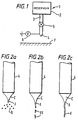
- FIG. 1 shows schematically a device 1 for carrying out electrohydrodynamic processing.
- the device 1 comprises a container or reservoir 2 of liquid coupled by a supply pipe 3 to an outlet 4 via a flow regulating valve 5 of conventional form.
- the valve 5 may be a manually or electrically operable valve.
- a voltage source 6 supplying a voltage of typically 15 to 25kV is coupled to the outlet 4 so as to cause liquid issuing from the outlet 4 to become charged. If the liquid is at least semiconducting (that is the liquid has a resistivity below about 10 9 ohm-m), the voltage source 5 may be coupled to the liquid upstream of the outlet 4.
- a surface area 7 such as an area of the skin of an animal, for example an area of skin of a human being, is positioned a few centimetres, for example from 5 to 10 cm, below the outlet 4 as shown schematically in Figure 1.
- the voltage source 6 is coupled to the outlet 4 by closing a switch (not shown in Figure 1) and the flow regulating valve 5 opened so that liquid is supplied under gravity to the outlet 4.
- the liquid is selected to be biologically compatible, that is not harmful or detrimental to the animal when deposited on its skin or an open wound, and will typically have a resistivity in the range of from approximately 10 2 to 10 8 ohm-metres and a viscosity in the region of from 0.1 to 1000 Poise or greater with the viscosity being dependent on whether a fibre, fibre fragments or segments or particles are to be formed.
- liquid issuing from the outlet 4 is subject to an intense electrical field which establishes a standing wave along the surface of the liquid producing cusps or cones which emit jets of charged liquid.
- the fact that the electrohydrodynamically produced material is charged and the animal body can effectively be considered earthed causes the material to deposit onto the surface 7 of the skin beneath the outlet 4.
- the material deposits swiftly, uniformly and gently by the energy contained in the electric field used to generate the material and will not overspray, nor become trapped in air streams and swept away from the target surface.
- One or more layers of such material may be deposited to provide a dressing to, for example, cover or protect, a wound or burn. This material being non-liquid should not cause the irritation which may arise from, for example, solvents if liquid droplets were applied to the skin.
- Relative movement may be effected between the nozzle 4 and the surface 7, in this example the surface 7 may be moved, to enable coverage of a large area.
- Figure 2a illustrates the situation where the liquid supplied to the outlet or nozzle 4 forms a spray of solid droplets or particles D while Figure 2b illustrates the situation where the liquid jet breaks up into fibrils FF and Figure 2c illustrates the situation where the liquid jet J forms a fibre F.
- Figures 2a to 2c show only one cone C and the associated jet J emanating from a nozzle 4.
- the actual number of cone and jets produced will, however, depend upon several factors, including the resistivity, permittivity and flow rate of the liquid, the dimensions of the outlet 4 and the applied electric field.
- the liquid is selected or formulated so as to become non-liquid, that is at least partially solid or gel-like, after the liquid has been separated by the applied electric field into liquid droplets.
- the liquid includes a solvent
- this may be achieved by, for example, selecting a liquid of such a volatility and viscosity and controlling the flow rate so that the solvent evaporates sufficiently to cause at least partial solidification or gellification only after droplet formation.
- the liquid is a melt which is held at an elevated temperature during supply to the outlet, then the liquid should be selected to have a melt temperature such that the liquid solidifies after liquid droplet formation. This may be facilitated by quenching using, for example, a cold inert gas or air stream.
- the liquid is selected or formulated and the flow rate controlled so that the liquid jet becomes at least partially non-liquid, that is solid or gel-like, before the liquid has been separated by the applied electric field into liquid droplets but so that the growth wave resulting from perturbation of the jet J remains sufficiently strong to inhibit formation of a fibre and causes the jet to break up into fibre fragments or fibrils FF.
- This may be achieved by selecting the liquid and flow rate so that the liquid begins to solidify (for example by evaporation in the case of a solution or by cooling in the case of a melt) before droplet formation and becomes relatively brittle so that the growth wave causes the nascent fibre to break into segments.
- Break up of the nascent fibre into fibrils may be facilitated by pulsing the voltage applied to the outlet 4 so as the create an energy pulse which sets up a resonant process to promote breaking up of the nascent fibre.
- the length of the fibrils is related to the pulse duration or frequency with, under ideal conditions, the fibril length being equal to the jet velocity divided by the pulse frequency so that, for example, if the jet velocity is 5ms -1 and a pulse frequency is 100kHz is used, the fibrils should have a length of 50 ⁇ m. Fibrils having lengths in the region of, for example, tens of micrometres to a few centimetres may be produced, depending upon the particular liquid and electrohydrodynamic process conditions used.
- the liquid is selected so as to become non-liquid, that is at least partially solid or gel-like, after issuing from the outlet, and the growth wave resulting from perturbation of the jet is attenuated so that the jet does not break up but forms a continuous fibre which has a length determined by the time for which the electrohydrodynamic process is continued, that is the time for which the voltage is applied.
- Attenuation of the growth wave may be achieved by the incipient solidification and/or by the nature of the liquid.
- Fibre production may be achieved by, for example, selecting a liquid which is highly volatile or has a highly volatile component so that solidification by evaporation occurs very quickly before droplet formation.
- fibres may be formed using a liquid comprising a polymer which on solidification tends, because of its viscosity and/or polymer chain morphology, to resist growth wave development.
- Fibres may be formed using a relatively high molecular weight polymer, for example a polymer having a molecular weight in the region of 140000 or more. Where the liquid used is a melt then choosing a liquid which solidifies to a relativity plastic state should promote fibre formation.
- the device 1 shown in Figure 1 uses a gravity feed to supply liquids to the outlet 4 which has the advantage of simplicity. It is most suitable for use in situations where the area of skin to which the dressing is to be applied can easily be moved beneath the outlet 4 or for use when the liquid to be supplied may be detrimentally affected by pumping.
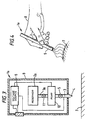
- Figure 3 illustrates a part cross-sectional view of another form of electrohydrodynamic processing device 1a.
- the device shown in Figure 3 is, as illustrated schematically in Figure 4, intended to be portable, in particular so as to be held in the hand 8 of a user.
- the device 1a shown in Figure 3 comprises a housing 9 within which is mounted a reservoir 2a of the liquid to be dispensed.
- the reservoir 2a may be formed as a collapsible bag so as to avoid any air contact with the liquid being dispensed.
- the reservoir 2a is coupled via a supply pipe 3a to a pump chamber 10 which is itself coupled via the supply pipe 3 and the flow regulating valve 5 to the outlet 4 in a similar manner to that shown in Figure 1.
- the voltage source 6 in this example is coupled to a user-operable switch SW1 which may be a conventional push button or toggle switch, for example.
- the voltage source 6 may comprise, for example a piezoelectric high voltage source of the type described in WO94/12285 or a battery operated electromagnetic high voltage multiplier such as that manufactured by Brandenburg, ASTEC Europe of Stourbridge West Midlands, UK or Start Spellman of Pulborough, Westshire, UK and typically provides a voltage in the range of from 10 to 25kV.
- a voltage control circuit comprising one or more resistor capacitor networks may be provided to ramp the voltage up smoothly.
- the reservoir 2a may be coupled to the pump chamber 10 by way of a valve 11 which may be a simple non-return or one way valve or may be an electrically or mechanically operable valve of any suitable type, for example a solenoid or piezoelectric valve, operable by a voltage supplied by the aforementioned control circuit.
- a valve 11 which may be a simple non-return or one way valve or may be an electrically or mechanically operable valve of any suitable type, for example a solenoid or piezoelectric valve, operable by a voltage supplied by the aforementioned control circuit.
- the pump chamber 10 may comprise any suitable form of pump, which provides a continuous substantially constant flow rate, for example an electrically operable pump such as a piezoelectric, or diaphragm pump or an electrohydrodynamic pump as described in EP-A-0029301 or EP-A-0102713 or an electroosmotic pump as described in WO94/12285 or a mechanically operable pump such as syringe pump operated or primed by a spring biassing arrangement operable by a user.
- an electrically operable pump such as a piezoelectric, or diaphragm pump or an electrohydrodynamic pump as described in EP-A-0029301 or EP-A-0102713 or an electroosmotic pump as described in WO94/12285
- a mechanically operable pump such as syringe pump operated or primed by a spring biassing arrangement operable by a user.
- the user In use of the device 1a shown in Figures 3 and 4, the user first positions the apparatus over the area 7 to which the material is to be applied, then actuates the switch SW1 and the pump of the pump chamber 10 to cause, when the valves 5 and 11 are opened, a stream of liquid to be supplied to the outlet 4 whence the liquid is subjected to the applied electric field as described above with reference to Figures 2a to 2c, forming charged matter which deposits onto the said surface 7 which may be the skin or on or within a wound.
- the user may move the device 1a relative to the area 7 to cover a large area.
- One or more layers may be formed in a manner similar to that described with reference to Figure 1.
- the device shown in Figures 3 and 4 has, however, the advantage that it is portable so allowing it to be used for, for example, first aid at the site of an accident and/or on relatively inaccessible areas of the body and does not rely on gravity feed.
- outlet or nozzle 4 may be used in the devices shown in Figures 1 and 3 and 4.
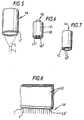
- Figures 5 to 8 illustrate schematically some examples.
- Another possibility is the fibre comminution site or nozzle described in WO95/26234.
- the nozzle 4a shown in Figure 5 comprises a hollow cylinder which is conductive or semiconductive material at least adjacent its end 4' where the voltage is to be applied in use and will in use produce one or more jets (one cusp or cone C and jet J are shown) depending upon the resistivity and flow rate of the liquid and the voltage applied to the outlet 4.
- the nozzle 4b shown in Figure 6 comprises two coaxial cylinders 40 and 41 at least one of which is conductive or semiconductive at least adjacent its end 40' or 41' where the voltage is applied and will in use produce a number of jets depending upon the resistivity and flow rate of the liquid and the applied voltage.
- the nozzle 4c shown in Figure 7 comprises a number of parallel capillary outlets 42 which are conductive or semiconductive at least adjacent their ends 42' where the voltage is applied. Each capillary outlet 42 will normally produce a single jet.
- the multiple nozzles shown in Figure 7 have the advantage that blockage of one nozzle by relatively viscous liquid does not significantly affect the operation of the device and also allow different liquids to be supplied from respective reservoirs to different ones of the nozzles.
- the nozzle 4d shown in Figure 8 comprises a slot-shaped nozzle defined between two parallel plates 43 which are conductive or semiconductive at least adjacent their ends 43' where the voltage is applied.
- the use of a slot nozzle when relatively highly viscous liquids are being used is advantageous because complete blockage of the nozzle is unlikely, as compared to the case where a relatively fine capillary nozzle is used, and a partial blockage should not significantly affect the functioning of the device because the liquid should be able to flow round any such partial blockage.
- the use of a slot-shaped nozzle outlet as shown in Figure 8 also allows a linear array of jets and thus of fibres, fibrils or particles or non-liquid droplets to be formed.
- the liquid being used is sufficiently conductive to enable the voltage to be applied to the liquid rather than the nozzle
- the nozzle may be formed of any suitable electrically insulative material which does not retain electrical charge for any significant length of time, for example glass or a semi-insulating plastic such as polyacetyl.
- the nozzle shown in Figure 7 is designed to produce a single jet per individual outlet 42.
- the nozzles shown in Figures 6 and 8 will in use produce a number of jets which extend generally along the electric field lines, with the number of jets depending upon, of course, the length of the slot ( Figure 8) or the diameter of the annulus ( Figure 6) and also upon the resistivity of the liquid, the flow rate and the applied voltage.
- some 10 or 20 jets may be formed per cm length of the nozzle, allowing the same number of fibres, for example, to be produced (spun).
- the applied voltage also affects the diameter of the resulting material.
- about 10 to 15 fibres of about 10 to 20 micrometres in diameter may be formed per cm length of the slot shown in Figure 8 from a liquid having a resistivity of about 10 9 ohm-m when the applied voltage is 15 kilovolts and a larger number, about 20, of fibres of smaller diameter may be formed per cm length of the slot when the applied voltage is 25 kilovolts.
- a liquid which is controlled to produce fibres is particularly advantageous for producing a wound or burn dressing because, as will be described below, deposition of the fibres onto the area being covered results in a network of crossing or interlinking fibres providing effectively an integral web or mat which has a high specific surface area and is thus highly absorbent to fluids, whilst being exceptionally light.
- a conventional dressing it enables good coverage over an area of skin so as, for example, to protect a wound but, unlike many conventional dressings, still enables, by virtue of the gaps between the network of fibres, air to pass through the dressing to the wound and pus and other detritus to pass from the wound, while preventing ingress of bacterial matter into the wound.
- dressings having a range of thickness, fluid permeability and mechanical strength can be formed enabling the dressing to be adapted for use on different types of wounds and burns including wounds arising from severe trauma such as say motor vehicle accidents, battle wounds etc, and chronic wounds including lesions such as ulcerated veins as well as, where appropriate, surgically exposed tissue.
- the permeability of the dressing has been found to be a function of the diameters and spacing of the fibres and the motion of the nozzle over the deposition area during application.
- liquids which form short fibrils or solid droplets will not generally form a cohesive mat or web of fibres.
- liquids which form fibrils or solid droplets may be used in combination with conventional dressings or with dressings formed by fibres as discussed above, for example fibrils or solid droplets produced using a method embodying the invention may be deposited into or on a wound and then covered with one or more layers of fibres produced by method embodying the invention or by a conventional dressing.
- Fibres, fibrils or droplets produced by electrohydrodynamic processing may be deposited onto a substrate, such as a dressing, for later application to the skin, a wound, burn or the like.
- Fibres have been successfully spun with polyhydroxybutyric acid, a bioresorbable polymer, and polyvinyl alcohol (PVA), a polymer soluble in water and alcohols such as methanol or propanol, and pharmaceutical preparations for wound care, such as "New Skin” (trade mark) marketed by SmithKline Beecham which comprises nitrocellulose in an organic solution (in particular it comprises ethyl acetate, isopropyl alcohol, amyl acetate, isobutyl alcohol, denatured alcohol, camphor and nitrocellulose).
- “New Skin” is normally applied to scratches and light wounds with a rod or paddle because it is too viscous to be applicable by conventional spray devices.
- “New Skin” has however been successfully sprayed by a method embodying the invention to form fibres of approximately 0.5 to 5 micrometres diameter which deposited uniformly onto skin, resulting in a firm skin-like web-film.
- neat (that is undiluted) "New Skin” was supplied at a flow rate of 4 millilitres per hour to a capillary nozzle of the type shown in Figure 5 in the form of a 1.1mm diameter thin-walled metal, generally stainless steel, tube.
- a voltage of 8.2kV was applied to the nozzle which was located approximately 50mm above an earthed deposition surface. Multiple fibres were formed and substantially uniformly deposited on the surface. Fibres have also been produced using undiluted "New Skin” (trade mark) with flow rates of from 1 millilitres per hour to 100 millilitres per hour.
- Polyvinyl alcohol has also been deposited in a similar manner to the "New Skin", using combinations of alcohol and water as solvent. Neat, undiluted PVA having a molecular weight of typically 15000 has been found to tend to form solid droplets when electrohydrodynamically processed while PVA having a molecular weight of about 140000 or more tends to form fibres. Low molecular weight PVA in a volatile solvent such as ethanol tends to break up into fibrils rather than continuous fibres. Thus, PVA having a molecular weight in the region of about 90000 to 140000 will tend to form fibrils and PVA fibrils having diameters of a few hundred nanometres and lengths of 0.5 to 10mm have been produced.
- annular nozzle of the type shown in Figure 6 was used to which a voltage of from 5kV to 15kV was applied.
- a 90% by volume solution of poly ⁇ -hydroxybutric acid (which is a bioresorbable polymer) in methylene chloride was supplied at a flow rate of from 5 micro litres per second to 50 micro litres per second to the nozzle which was located at a distance of about 5cm from human skin.
- a covering layer of fibres was formed on the skin with the fibres having diameters, dependent on the applied voltage and flow rate, in the range of from about 10 micrometres to about 50 micrometres.
- the apparatus shown in Figure 1 was used with a thin-walled, generally stainless steel, capillary nozzle of the type shown in Figure 5 having a 1.1mm external diameter.
- the reservoir was filled with polylactic acid having a molecular weight of 144000 dissolved 10% by mass in acetone and the flow regulator was controlled to provide a flow rate of 10 millilitres per hour.
- a voltage of 12 kV was applied to the nozzle which was located 8cm away from and perpendicular to a flat earthed counter electrode provided to simulate a skin surface.
- This experiment was also repeated using a flow rate of 6.0 millilitres per hour and a nozzle voltage of 11.4kV.
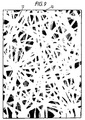
- the surface of the flat plate was covered by a network or mass of randomly distributed fibres having diameters typically in the region of from 2 micrometres to 7 micrometres.
- the fibres deposit readily onto capacitive or earthed surfaces without any of the normal problems of applying very low mass high specific surface materials and the electrical field ensures that the fibres deposit swiftly, gently and substantially uniformly.
- Figure 9 shows a copy of an image produced by scanning electron microscope of a typical mat or web of fibres 12 on a plate 13.
- the fibres have, typically, a diameter of approximately 5 ⁇ m.
- the fibres shown in Figure 9 are relatively randomly distributed because their relatively low mass, and thus low inertia, and high charge to mass ratio means that their movement and thus location of deposition on the surface is strongly influenced by the fact that they are all similarly charged fibres. This also results in the fibres crossing one another and possibly even blending together which should increase the overall mechanical integrity of the web or mat.
- FIG. 10 shows an example of fibres 15 of about 50 to 100 micrometres in diameter deposited onto a substrate using a slot-shaped nozzle of the type shown in Figure 8. As can be seen from Figure 10, a single pass of the nozzle produces a set of approximately parallel tracks and, with two or more passes, a relatively dense material akin to a textile can be produced.
- the fibres, fibrils or droplets produced using the method embodying the invention consist simply of an inert polymer which may be a bioresorbable polymer such as polyhydroxybutyric acid, polyvinyl alcohol, polyglycolic acid or polylactic acid.
- Biologically active ingredients may, however, be added to the liquid before it is supplied to the outlet nozzle 4.
- the liquid may comprise a solution, suspension, microsuspension, emulsion, microemulsion, gel or even a melt containing the active component or components.
- Possible active components are one or more of the following, namely pharmaceutical compounds such as analgesics, antiseptics, antibiotics, bactericides, antifungals, antiparasitics, anti-inflammatory agents, vasodilators (such as minoxidil which is believed to promote wound epithelialization and neovascularization), agents such as proteolytic enzymes for debridement and tissue repair promoting materials such as for example cytokines for stimulating cytokinetic activity to promote essential cell activities, for example to stimulate dendritic growth, growth factors such as fibroblast growth factor (FGF), epithelial growth factor (EGF), transforming growth factor (TGF) that are believed to reduce scarring and others that may be used to promote or otherwise control the sequence of events essential to natural tissue repair, cells, peptides, polypeptides, insulin, immune suppressants or stimulants and vaccines.
- Another possible active components are DNA or other genetic matter for gene therapy, surface binding or surface recognising agents such as surface protein A, and surfactants.
- the active ingredient may comprise an adjuvant that is a pharmacological agent added to a drug to increase or aid its effect or an immunological agent that increases the antigenic response.
- the fibrils may actually stick into the surface, for example skin or soft tissue, onto which they are deposited so enabling, for example, the supply of drugs and other biologically active agents beneath the skin or into the soft tissue, and may for example be used to carry DNA to cells.
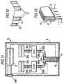
- Figure 11 illustrates a device 1b embodying the present invention.
- the device 1b shown in Figure 11 is similar to that shown in Figure 3 but comprises two reservoirs 20a and 20b each coupled by respective supply pipes 30a and 30b and possibly by non-return valves 11a and 11b to a respective pump chamber 100a and 100b coupled via a respective valve 50a and 50b to a respective liquid supply pipe 30 which terminates in a respective outlet 44 and 45 arranged so that the outlet 45 is coaxial with and extends around the outlet 44.
- Figure 12 shows the outlets 44 and 45 on an enlarged scale.
- the device 1b shown in Figure 11 allows different forms of liquid to be supplied to the electrohydrodynamic processing site provided by the outlets 44 and 45.
- the reservoir 20a coupled to the inner outlet 44 may contain a supply of a biologically active ingredient such as a pharmaceutical or a solution of DNA for example, while the reservoir 20b coupled to the outer nozzle 45 may contain a supply of a polymer solution of the type discussed above, for example polyhydroxybutyric acid dissolved in methylene chloride.
- the device shown in Figure 11 is operated in a similar manner to the device shown in Figure 3.
- the switch SW1 is first activated to supply the required voltages, typically 10 to 25kv
- the flow regulating valves 50a and 50b are then opened to provide the required flow from each of the nozzles 44 and 45 and the pumps 100a and 100b and valves 11a and 11b, if present, activated to supply liquid to the respective nozzles 44 and 45.
- the outlets of the two coaxial nozzles are designed to promote laminar flow so that the polymer containing solution issues from the nozzle 45 so as to surround the other liquid.
- the liquids issuing from the combined nozzle can be caused to form a fibre or fibrils in which the biologically active ingredient forms a cylindrical centre core of the fibre or fibril or micro capsules in which the biologically active ingredient is completely encapsulated within the polymer and may still be in a liquid form.
- microcapsule formation it has been found preferable to reduce the percentage polymer in solution and to use a much reduced molecular weight polymer. For example a resin such as neoprene chlorinated rubber dissolved at more than about 10% by weight in trichloroethane will tend to spray fibres.
- a less volatile solvent such as, for example, propylene glycol ether
- microcapsules may be formed.
- Microcapsules have been produced using PVA of low molecular weight, for example a molecular weight of about 15000, dissolved to a dilution of between about 2.5 per cent and 5 per cent by volume in water or alcohol with a flow rate of about 1.0 microlitres per second. Production of microcapsules may be enhanced by using two reactive monomers one of which is placed in each of the two liquids to react during comminution.
- Composite products embodying the invention produced using the device shown in Figures 11 and 12 may be used to form a dressing in the manner described above where the composite product is in the form of fibres or long fibrils allowing for controlled release of the active ingredient as the bioresorbable polymer degrades.
- the composite products produced are fibres, fibrils or microcapsules, then these may be applied to the surface of the skin or into a wound in combination with, for example, a conventional dressing or a dressing produced from comminuted fibres. Material from the core of a fibre or fibril may be released from the ends of the fibre or fibril.
- Material from the core of a fibre, fibril or microcapsule may be released through the coating if the coating is permeable to the material contained within it or may be released as a result of the outer coating being breached, for example by chemical or enzymic attack which causes the outer coating to dissolve or degrade, by bioresorption or biodegradation of the coating, or as a result of temperature changes or application of pressure which causes the outer coating to rupture.
- Composite products made up of three or more different layers of material may be formed by increasing the number of coaxial nozzles.
- the outlet nozzle of the device shown in Figure 11 may comprise a number of sets of coaxial outlet nozzles 44 and 45 in a manner similar to that shown in Figure 7 for single outlet nozzles. This would allow different active ingredients to be supplied to different ones of the inner nozzles 44. The different active ingredients can thus be kept apart until actual use which is of particular advantage where the active ingredients react to form a product which itself has a low shelf life.
- the nozzle shown in Figure 12 is deliberately designed to avoid mixing between the two liquids which are generally selected so as to be immiscible thereby enabling production of a cored fibre, fibril or microcapsule.
- Figure 13 shows an alternative form of nozzle which may be used in the device shown in Figure 11 but does not fall within the scope of the invention claimed.
- the nozzle shown in Figure 13 is a slot-nozzle similar to that shown in Figure 8 but provided with two separate channels 46 and 47 coupled to respective ones of the liquid supply pipes so that each channel receives a different liquid.
- the outlets of the channels 46 and 47 are designed so as to create turbulence and therefore mixing of two liquids at the outlet. This arrangement may be used where, for example, it is desired to have some control over the amount of active ingredient which may be incorporated into a liquid or to combine two liquids which then react.
- a polyurethane foam has been formed by reacting a solution of urethane supplied via one of the nozzles with a blowing agent supplied by the other nozzle to spray a flexible foam deposit into a wound to form a cavity wound dressing.
- This arrangement has the advantage that the dressing will conform to the contours of a cavity wound and may be applied with clerical cleanliness without handling.
- an active ingredient such as a pharmaceutically active ingredient may be incorporated into one of the two liquids or mixed with the two liquids.
- the nozzle shown in Figure 13 may also be used to, for example, bring reactive liquids together at the nozzle to deposit reacting or reactive product onto the skin or into a wound which should be of advantage where the reactive product has a very short lifetime and cannot be stored.
- the nozzle shown in Figure 13 has been used experimentally to produce a fibrin mat by supplying the enzyme thrombin to one channel and fibrinogen to the other channel.
- the device shown in Figure 11 may be modified to provide two separate spaced nozzles and the voltage source arranged to charge the two nozzles to voltages of opposite polarity in a manner similar to that described in WO94/12285 so as to enable liquid droplets charged to one polarity to rapidly coalesce with droplets charged to the other polarity to form ultra-small particles of from sub-micron to a few tens of microns in diameter.
- ultra small droplets containing, for example the enzyme thrombin may be sprayed at one polarity so as to rapidly coalesce with droplets of the opposite polarity containing fibrinogen to deposit a fast reacting fibrin mat to cause blood clotting, for wound sealing or for adhesion.
- a method embodying the invention may also be used to produce material capable of transfecting resident cells in situ with genetic material in order to regulate cell responses.
- a method embodying the invention may be used to produce microcapsules comprising DNA encapsulated in a microcapsules or complexed with an appropriate lipid material for transfecting cells.
- Phospholipid microcapsules encapsulating DNA may be produced by a method embodying the invention.
- Other biological material such as proteins may be similarly encapsulated or complexed with an appropriate lipid material. Proteins may also be incorporated in the lipid layer.
- Surface binding or surface recognising agents such as surface protein A may be incorporated into microcapsules, especially phospholipid microcapsules, for selecting targets such as cancer cells, epithelial cells etc.
- surfactants such as soya lecithin available from Sigma Pharmaceuticals may be incorporated in the outer surface of fibres, microcapsules or fibrils.
- Fibres, fibrils or droplets or capsules produced by a method embodying the invention may be coated with substances such as surfactants such as soya lecithin or with, for example, DNA which is relatively sticky.
- surfactants such as soya lecithin
- DNA which is relatively sticky.
- a separate spraying device which may be a conventional or electrohydrodynamic spraying device, may be provided so as to direct, for example, an oppositely charged spray or cloud of the coating material into the path of the material produced by the apparatus shown in Figure 1, 2 or 11, for example.
- Figure 14 illustrates schematically a modified form of the device shown in Figure 11 which may be suitable for producing fibrils or microcapsules for inhalation.
- the device shown in Figure 14 differs from that shown in Figure 11 merely by the provision of air vents 62 and electrical discharge 60 means for discharging the fibrils or microcapsules and an outlet 50 adapted to receive a tube for insertion into the mouth or trachea of a user or to receive a mask to cover the mouth and nose of a user where both oral and nasal inhalation are required.
- the electrical discharging means may comprise, for example, an earthed discharge electrode 61 so as to produce gaseous ions of the opposite polarity to the charged fibrils or microcapsules so that the fibrils or microcapsules are discharged for inhalation by a user.
- the discharging means may be brought into operation by the active inhalation by the user as described in, for example, WO94/14543.
- the provision of the electrical discharge means enables the fibrils or microcapsules to be delivered to the upper or lower regions of the lungs rather than simply to the nasal passages.
- the actual location to which the fibrils or microcapsules are delivered can be controlled by controlling any residual electrical charge and the precise dimensions of the fibrils or microcapsules may be controlled by controlling the volatility, flow rate and voltage applied to the nozzle.
- the material for oral delivery may comprise liposome encapsulated or complexed DNA for transfecting cells or may, for example comprise biologically active ingredients such as peptides, polypeptides and other large biomolecules such as insulin or growth factor, and active pharmaceutical components for enabling delivery of the active component into the blood stream via the lung.
- biologically active ingredients such as peptides, polypeptides and other large biomolecules such as insulin or growth factor
- active pharmaceutical components for enabling delivery of the active component into the blood stream via the lung.
- the choice of coating material, the permeability and/or thickness of the coating may be adjusted to adjust the timing of release of the active ingredient.
- the coating comprises a bioresorbable or biodegradable polymer
- the half-life of the polymer may be controlled by controlling the permeability and/or thickness of the polymer coating by, for a specific formulation, controlling the flow rate and voltage.
- a method embodying the invention may also be used to supply material to body cavities other than the respiratory system.
- the material will be at least partially electrically discharged before supply and means may be provided for forming an air or inert gas flow to assist the supply of the material to the body cavity.
- the device embodying the invention may be mounted to an endoscope or like instrument enabling the device to be inserted into the body and to be positioned at the site where the material is required.
- the material may comprise any of the fibres, fibrils, particles and microcapsules mentioned above.
- a method embodying the invention may also be used in a production process to form fibrils or particles comprising a biologically active ingredient and/or fibrils or microcapsules having a core of a biologically active ingredient which may themselves be encapsulated in conventional orally ingestible capsules, enabling, especially in the case of microcapsules, good control over the release of the active material.
- a method and device embodying the invention may also be used for non-medical purposes.
- coatings of fibres, fibrils, particles or microcapsules may be formed on substrates such as paper with good control of the thickness and uniformity of the coating.
- adhesive may be deposited onto a substrate using a method embodying the invention.
- Materials formed of two or more components which have only a short-shelf life when mixed together may be formed in a timely manner using a method embodying the present invention by encapsulating the respective components in respective fibres, fibrils or microcapsules so that mixing of the various components only occurs when the components are released from the encapsulating material by, for example, leaching through the encapsulating material, rupture by pressure being applied to the encapsulating material, temperature, or degradation, for example bioresorption or biodegradation, of the encapsulant.
- Such a method may be used to form, for example, two component adhesives which may be applied separately or simultaneously to a surface as cored fibres, fibrils or microcapsules by a method embodying the invention.
- Other materials such as perfumes, insecticides, aromas, vapours, inks, dyes, lubricants, insect repellents etc., may be encapsulated in fibres, fibrils or microcapsules and deposited on a surface using a method embodying the invention, allowing the encapsulated ingredient to be released in a time-controlled manner as discussed in the previous paragraph, for example by application of pressure to the surface.
- a method embodying the invention may also be used to produce a protective coating which may contain an active protective ingredient such as an anti-corrosive or a lubricant.
- an active protective ingredient such as an anti-corrosive or a lubricant.
- temporary protective coatings of delicate articles or articles liable to corrosion may be provided by depositing a web or mat on the surface of the article using a method embodying the invention.
- webs or mats formed using a method embodying the invention may also be sprayed or deposited over, for example, delicate crops such as grapes or strawberries so as to protect them from environmental effects such as frost, sun-damage, etc.
- Such a web may incorporate active ingredients such as insecticides, fungicides, miticides and the like to further protect the crop.
- the capacitive nature of materials such as skin and the moisture content of the air should be sufficient for deposition onto a surface to occur simply by electrostatic attraction.
- a method and device embodying the invention may also be used for supplying material to cavities other than body cavities and to concave surfaces.
- the charged matter will generally be at least partially electrically discharged before it reaches the cavity or concave surface.
- the term “particle” includes solid, partially solid and gel-like droplets and microcapsules which incorporate solid, partially solid, gel-like or liquid matter.
- active ingredient means material which is compatible with and has an affect on the substrate or body to which it is to be applied and the term “biologically active ingredient” or “biologically active material” means material which is compatible with and has an affect (which may for example be biological, chemical or biochemical) on the animal or plant to which it is to be applied and includes, for example, medicaments such as proprietary medicines, pharmaceutical medicines and veterinary medicines, vaccines, genetic material such as DNA, cells and the like.
Landscapes
- Health & Medical Sciences (AREA)
- Engineering & Computer Science (AREA)
- Animal Behavior & Ethology (AREA)
- Life Sciences & Earth Sciences (AREA)
- Veterinary Medicine (AREA)
- Public Health (AREA)
- General Health & Medical Sciences (AREA)
- Textile Engineering (AREA)
- Anesthesiology (AREA)
- Hematology (AREA)
- Heart & Thoracic Surgery (AREA)
- Mechanical Engineering (AREA)
- Chemical & Material Sciences (AREA)
- Biomedical Technology (AREA)
- Bioinformatics & Cheminformatics (AREA)
- Materials Engineering (AREA)
- Epidemiology (AREA)
- Nuclear Medicine, Radiotherapy & Molecular Imaging (AREA)
- Pulmonology (AREA)
- Pharmacology & Pharmacy (AREA)
- Organic Chemistry (AREA)
- Medicinal Chemistry (AREA)
- General Chemical & Material Sciences (AREA)
- Chemical Kinetics & Catalysis (AREA)
- Dermatology (AREA)
- Materials For Medical Uses (AREA)
- Application Of Or Painting With Fluid Materials (AREA)
- Electrostatic Spraying Apparatus (AREA)
- Medicinal Preparation (AREA)
- Media Introduction/Drainage Providing Device (AREA)
- Spinning Methods And Devices For Manufacturing Artificial Fibers (AREA)
- Coating Apparatus (AREA)
- Beans For Foods Or Fodder (AREA)
- Polymerisation Methods In General (AREA)
Priority Applications (1)
| Application Number | Priority Date | Filing Date | Title |
|---|---|---|---|
| EP03077325A EP1388371B1 (en) | 1996-07-23 | 1997-07-22 | A dispensing device and method for forming material |
Applications Claiming Priority (5)
| Application Number | Priority Date | Filing Date | Title |
|---|---|---|---|
| GBGB9615387.9A GB9615387D0 (en) | 1996-07-23 | 1996-07-23 | Dispensing device and process |
| GB9615387 | 1996-07-23 | ||
| GBGB9620064.7A GB9620064D0 (en) | 1996-07-23 | 1996-09-26 | Dispensing device and processes |
| GB9620064 | 1996-09-26 | ||
| PCT/GB1997/001968 WO1998003267A1 (en) | 1996-07-23 | 1997-07-22 | A dispensing device and method for forming material |
Related Child Applications (1)
| Application Number | Title | Priority Date | Filing Date |
|---|---|---|---|
| EP03077325A Division EP1388371B1 (en) | 1996-07-23 | 1997-07-22 | A dispensing device and method for forming material |
Publications (2)
| Publication Number | Publication Date |
|---|---|
| EP0912251A1 EP0912251A1 (en) | 1999-05-06 |
| EP0912251B1 true EP0912251B1 (en) | 2004-04-07 |
Family
ID=26309735
Family Applications (2)
| Application Number | Title | Priority Date | Filing Date |
|---|---|---|---|
| EP97932918A Expired - Lifetime EP0912251B1 (en) | 1996-07-23 | 1997-07-22 | A dispensing device and method for forming material |
| EP03077325A Expired - Lifetime EP1388371B1 (en) | 1996-07-23 | 1997-07-22 | A dispensing device and method for forming material |
Family Applications After (1)
| Application Number | Title | Priority Date | Filing Date |
|---|---|---|---|
| EP03077325A Expired - Lifetime EP1388371B1 (en) | 1996-07-23 | 1997-07-22 | A dispensing device and method for forming material |
Country Status (7)
| Country | Link |
|---|---|
| EP (2) | EP0912251B1 (enExample) |
| JP (2) | JP4077035B2 (enExample) |
| AT (1) | ATE263629T1 (enExample) |
| AU (1) | AU3628497A (enExample) |
| CA (1) | CA2296334C (enExample) |
| DE (1) | DE69728539T2 (enExample) |
| WO (1) | WO1998003267A1 (enExample) |
Cited By (3)
| Publication number | Priority date | Publication date | Assignee | Title |
|---|---|---|---|---|
| US8535296B2 (en) | 2002-10-28 | 2013-09-17 | Smith & Nephew Plc | Apparatus for aspirating, irrigating and cleansing wounds |
| US8998866B2 (en) | 2010-07-02 | 2015-04-07 | Smith & Nephew Plc | Provision of wound filler |
| US9044569B2 (en) | 2004-04-28 | 2015-06-02 | Smith & Nephew Plc | Wound dressing apparatus and method of use |
Families Citing this family (124)
| Publication number | Priority date | Publication date | Assignee | Title |
|---|---|---|---|---|
| US6433154B1 (en) * | 1997-06-12 | 2002-08-13 | Bristol-Myers Squibb Company | Functional receptor/kinase chimera in yeast cells |
| CN1163937C (zh) * | 1998-02-16 | 2004-08-25 | 松下电器产业株式会社 | 涂料以及采用该涂料的电子管 |
| GB2345010B (en) | 1998-12-17 | 2002-12-31 | Electrosols Ltd | A delivery device |
| US6397838B1 (en) * | 1998-12-23 | 2002-06-04 | Battelle Pulmonary Therapeutics, Inc. | Pulmonary aerosol delivery device and method |
| US7615373B2 (en) | 1999-02-25 | 2009-11-10 | Virginia Commonwealth University Intellectual Property Foundation | Electroprocessed collagen and tissue engineering |
| US6592623B1 (en) | 1999-08-31 | 2003-07-15 | Virginia Commonwealth University Intellectual Property Foundation | Engineered muscle |
| US20020081732A1 (en) | 2000-10-18 | 2002-06-27 | Bowlin Gary L. | Electroprocessing in drug delivery and cell encapsulation |
| US20020042128A1 (en) * | 2000-09-01 | 2002-04-11 | Bowlin Gary L. | Electroprocessed fibrin-based matrices and tissues |
| GB9910505D0 (en) * | 1999-05-06 | 1999-07-07 | Electrosols Ltd | A method and apparatus for manufacturing consumable tablets |
| US6737447B1 (en) | 1999-10-08 | 2004-05-18 | The University Of Akron | Nitric oxide-modified linear poly(ethylenimine) fibers and uses thereof |
| US6753454B1 (en) * | 1999-10-08 | 2004-06-22 | The University Of Akron | Electrospun fibers and an apparatus therefor |
| DE60044747D1 (de) * | 1999-10-08 | 2010-09-09 | Univ Akron | Gesichtsmaske aus elektrogesponnenen fasern und ihre verwendung |
| CN1400934A (zh) | 2000-02-18 | 2003-03-05 | 冲激注射技术股份有限公司 | 制造纤维的方法和设备 |
| WO2001062397A1 (en) * | 2000-02-25 | 2001-08-30 | Advanced New Materials S.A. | Method and apparatus for spraying a material |
| WO2001070417A2 (en) * | 2000-03-24 | 2001-09-27 | Advanced New Materials S.A | Method and apparatus for applying a material by means of electro hydro dynamic jetting |
| DE60142043D1 (de) * | 2000-04-03 | 2010-06-17 | Battelle Memorial Inst Columbu | Ausgabevorrichtungen und flüssigformulierungen |
| AU2001261625B2 (en) * | 2000-05-16 | 2006-04-06 | Regents Of The University Of Minnesota | High mass throughput particle generation using multiple nozzle spraying |
| EP1333808B1 (en) * | 2000-10-18 | 2012-07-25 | Virginia Commonwealth University Intellectual Property Foundation | Electroprocessed composition used in drug delivery and cell encapsulation |
| SG160201A1 (en) * | 2000-10-18 | 2010-04-29 | Univ Virginia Commonwealth | Electroprocessing in drug delivery and cell encapsulation |
| EP1345743B1 (en) * | 2000-11-17 | 2008-07-23 | Virginia Commonwealth University Intellectual Property Foundation | Electroprocessed collagen |
| JP2010163435A (ja) * | 2000-11-17 | 2010-07-29 | Virginia Commonwealth Univ Intellectual Property Foundation | 電気処理されたコラーゲン |
| ES2180405B1 (es) * | 2001-01-31 | 2004-01-16 | Univ Sevilla | Dispositivo y procedimiento para producir chorros liquidos compuestos multicomponentes estacionarios y capsulas multicomponente y/o multicapa de tamaño micro y nanometrico. |
| ZA200306564B (en) * | 2001-02-26 | 2004-10-15 | Optinose As | Nasal devices. |
| US20040131673A1 (en) * | 2001-03-22 | 2004-07-08 | Coffee Ronald Alan | Manufacturing dissolvable dosage forms |
| GB0115227D0 (en) * | 2001-03-22 | 2001-08-15 | Electrosols Ltd | Manufacturing dissolvable dosage forms |
| JP2005501810A (ja) * | 2001-03-22 | 2005-01-20 | バテル メモリアル インスティチュート | ポリマーおよび懸濁粒子を含有する電気流体力学的噴霧用の液体形成物 |
| US6713011B2 (en) | 2001-05-16 | 2004-03-30 | The Research Foundation At State University Of New York | Apparatus and methods for electrospinning polymeric fibers and membranes |
| US7247338B2 (en) | 2001-05-16 | 2007-07-24 | Regents Of The University Of Minnesota | Coating medical devices |
| US6685956B2 (en) | 2001-05-16 | 2004-02-03 | The Research Foundation At State University Of New York | Biodegradable and/or bioabsorbable fibrous articles and methods for using the articles for medical applications |
| US6821479B1 (en) | 2001-06-12 | 2004-11-23 | The University Of Akron | Preservation of biological materials using fiber-forming techniques |
| DE10135501A1 (de) * | 2001-07-20 | 2003-01-30 | Wella Ag | Elektrosol-Haarspray |
| US6790455B2 (en) | 2001-09-14 | 2004-09-14 | The Research Foundation At State University Of New York | Cell delivery system comprising a fibrous matrix and cells |
| US8367570B2 (en) | 2002-04-04 | 2013-02-05 | The University Of Akron | Mechanically strong absorbent non-woven fibrous mats |
| BRPI0309022A2 (pt) * | 2002-04-04 | 2016-11-08 | Univ Akron | conjuntos de fibra não tecida |
| AU2003223513A1 (en) * | 2002-04-05 | 2003-10-27 | Virginia Commonwealth University Intellectual Property Foundation | Electroprocessing of materials useful in drug delivery and cell encapsulation |
| AU2003240939A1 (en) * | 2002-05-28 | 2003-12-12 | Virginia Commonwealth University Intellectual Property Foundation | Electroprocessed collagen and tissue engineering |
| GB0219618D0 (en) * | 2002-08-22 | 2002-10-02 | Battelle Memorial Institute | Woundcare |
| US7846141B2 (en) | 2002-09-03 | 2010-12-07 | Bluesky Medical Group Incorporated | Reduced pressure treatment system |
| EP1549255A4 (en) | 2002-09-13 | 2007-12-19 | Coopervision Inc | DEVICES AND METHOD FOR IMPROVING THE SEA THICKNESS |
| WO2005044006A1 (en) * | 2003-11-05 | 2005-05-19 | Battelle Memorial Institute | Quick dissolving agrochemical products |
| EP1737502B1 (en) | 2004-01-22 | 2014-01-15 | The University of Akron | Polymer no donor predrug nanofiber coating for medical devices |
| NL1025556C1 (nl) * | 2004-02-24 | 2005-08-26 | Jacob Korevaar | Inrichting en werkwijze voor het toedienen van een fluïdum aan een mens of zoogdier. |
| US7471437B2 (en) | 2004-03-31 | 2008-12-30 | Eastman Kodak Company | Electrochromic materials and devices |
| US8062272B2 (en) | 2004-05-21 | 2011-11-22 | Bluesky Medical Group Incorporated | Flexible reduced pressure treatment appliance |
| US10058642B2 (en) | 2004-04-05 | 2018-08-28 | Bluesky Medical Group Incorporated | Reduced pressure treatment system |
| US7909805B2 (en) | 2004-04-05 | 2011-03-22 | Bluesky Medical Group Incorporated | Flexible reduced pressure treatment appliance |
| US7134857B2 (en) | 2004-04-08 | 2006-11-14 | Research Triangle Institute | Electrospinning of fibers using a rotatable spray head |
| US7762801B2 (en) | 2004-04-08 | 2010-07-27 | Research Triangle Institute | Electrospray/electrospinning apparatus and method |
| US7297305B2 (en) | 2004-04-08 | 2007-11-20 | Research Triangle Institute | Electrospinning in a controlled gaseous environment |
| US7592277B2 (en) * | 2005-05-17 | 2009-09-22 | Research Triangle Institute | Nanofiber mats and production methods thereof |
| JP4439517B2 (ja) * | 2004-05-13 | 2010-03-24 | 株式会社ネクスト21 | 経内視鏡手術に用いる止血と、癒着の防止装置 |
| US20050259221A1 (en) | 2004-05-20 | 2005-11-24 | Coopervision, Inc | Corneal onlays and wavefront aberration correction to enhance vision |
| DE102004026745B4 (de) | 2004-05-28 | 2013-06-20 | Justus-Liebig-Universität Giessen | Verfahren und Vorrichtung zur Ausbringung von nanoskaligen Polymerfasern als Träger für landwirtschaftliche Wirkstoffe |
| US7390760B1 (en) | 2004-11-02 | 2008-06-24 | Kimberly-Clark Worldwide, Inc. | Composite nanofiber materials and methods for making same |
| CN101137446B (zh) * | 2005-02-11 | 2010-06-09 | 巴特尔纪念研究所 | 电流体动力气雾剂分配装置及喷射方法 |
| EP3056335A1 (en) | 2005-05-16 | 2016-08-17 | The University of Akron | Mechanically strong absorbent non-woven fibrous mats |
| DE102005033681A1 (de) * | 2005-07-19 | 2007-02-08 | Kunststoff-Fröhlich GmbH | Plastisch geformter Körper, thermoplastisch verformbares Granulat, Hohlstruktur und Verfahren zu deren Herstellung |
| WO2007089883A2 (en) | 2006-01-31 | 2007-08-09 | Nanocopoeia, Inc. | Nanoparticle coating of surfaces |
| US7951428B2 (en) | 2006-01-31 | 2011-05-31 | Regents Of The University Of Minnesota | Electrospray coating of objects |
| US9108217B2 (en) | 2006-01-31 | 2015-08-18 | Nanocopoeia, Inc. | Nanoparticle coating of surfaces |
| US8297959B2 (en) * | 2006-05-03 | 2012-10-30 | Terapia Celular, Ln, Inc. | Systems for producing multilayered particles, fibers and sprays and methods for administering the same |
| US8168229B2 (en) | 2006-05-18 | 2012-05-01 | Lnk Chemsolutions, Llc | Methods for making a multicomponent hemostatic dressing |
| US7629030B2 (en) * | 2006-12-05 | 2009-12-08 | Nanostatics, Llc | Electrospraying/electrospinning array utilizing a replacement array of individual tip flow restriction |
| US9040816B2 (en) | 2006-12-08 | 2015-05-26 | Nanocopoeia, Inc. | Methods and apparatus for forming photovoltaic cells using electrospray |
| WO2009042128A1 (en) | 2007-09-25 | 2009-04-02 | The University Of Akron | Bubble launched electrospinning jets |
| GB0722820D0 (en) | 2007-11-21 | 2008-01-02 | Smith & Nephew | Vacuum assisted wound dressing |
| ES2776709T3 (es) | 2007-11-21 | 2020-07-31 | Smith & Nephew | Apósito para heridas |
| ES2555204T3 (es) | 2007-11-21 | 2015-12-29 | T.J. Smith & Nephew Limited | Dispositivo de succión y venda |
| GB0723875D0 (en) | 2007-12-06 | 2008-01-16 | Smith & Nephew | Wound management |
| US20130096518A1 (en) | 2007-12-06 | 2013-04-18 | Smith & Nephew Plc | Wound filling apparatuses and methods |
| US11253399B2 (en) | 2007-12-06 | 2022-02-22 | Smith & Nephew Plc | Wound filling apparatuses and methods |
| GB0803564D0 (en) | 2008-02-27 | 2008-04-02 | Smith & Nephew | Fluid collection |
| US9943401B2 (en) | 2008-04-04 | 2018-04-17 | Eugene de Juan, Jr. | Therapeutic device for pain management and vision |
| RU2508133C2 (ru) * | 2008-04-21 | 2014-02-27 | МакНЕЙЛ-ППС, ИНК. | Устройство доставки для местного применения, содержащее две аэрозольные камеры |
| JP5178309B2 (ja) * | 2008-05-09 | 2013-04-10 | オリンパス株式会社 | 薬液投与装置 |
| GB0902816D0 (en) | 2009-02-19 | 2009-04-08 | Smith & Nephew | Fluid communication path |
| GB0905575D0 (en) | 2009-03-31 | 2009-05-13 | Stfc Science & Technology | Electrospinning nozzle |
| EP2490620A4 (en) | 2009-10-23 | 2017-03-22 | Forsight Labs, Llc | Conformable therapeutic shield for vision and pain |
| US8591025B1 (en) | 2012-09-11 | 2013-11-26 | Nexisvision, Inc. | Eye covering and refractive correction methods for LASIK and other applications |
| US20130066283A1 (en) | 2009-10-23 | 2013-03-14 | Nexisvision, Inc. | Corneal Denervation for Treatment of Ocular Pain |
| US9061095B2 (en) | 2010-04-27 | 2015-06-23 | Smith & Nephew Plc | Wound dressing and method of use |
| CN103281995B (zh) | 2010-10-25 | 2016-04-06 | 内希斯视觉股份有限公司 | 识别针对视力的眼睛覆盖物的方法和设备 |
| GB201020005D0 (en) | 2010-11-25 | 2011-01-12 | Smith & Nephew | Composition 1-1 |
| JP6078472B2 (ja) | 2010-11-25 | 2017-02-08 | スミス アンド ネフュー ピーエルシーSmith & Nephew Public Limited Company | 組成物i−iiおよび生成物ならびにそれらの使用 |
| US9194058B2 (en) * | 2011-01-31 | 2015-11-24 | Arsenal Medical, Inc. | Electrospinning process for manufacture of multi-layered structures |
| US9423632B2 (en) | 2012-04-20 | 2016-08-23 | Nexisvision, Inc. | Contact lenses for refractive correction |
| AU2012249773A1 (en) | 2011-04-28 | 2013-11-07 | Nexisvision, Inc. | Eye covering and refractive correction methods and apparatus having improved tear flow, comfort, and/or applicability |
| US12044905B2 (en) | 2011-04-28 | 2024-07-23 | Journey1 Inc | Contact lenses for refractive correction |
| US20150159066A1 (en) | 2011-11-25 | 2015-06-11 | Smith & Nephew Plc | Composition, apparatus, kit and method and uses thereof |
| US9465233B2 (en) | 2012-04-20 | 2016-10-11 | Nexisvision, Inc. | Bimodular contact lenses |
| US10519434B2 (en) | 2012-07-13 | 2019-12-31 | Diomics Corporation | Biologic sample collection devices and methods of production and use thereof |
| CZ2012514A3 (cs) * | 2012-07-27 | 2013-05-02 | Contipro Biotech S.R.O. | Zvláknovací tryska pro výrobu nano a mikrovlákenných materiálu slozených z vláken s koaxiální strukturou |
| EP2703031A1 (en) | 2012-08-28 | 2014-03-05 | Universität Bern | Electrospray device |
| WO2014120455A1 (en) * | 2013-02-04 | 2014-08-07 | Arsenal Medical, Inc. | Electrospinning process for fiber manufacture |
| US20160120706A1 (en) | 2013-03-15 | 2016-05-05 | Smith & Nephew Plc | Wound dressing sealant and use thereof |
| EP2968647B1 (en) | 2013-03-15 | 2022-06-29 | Smith & Nephew plc | Wound dressing sealant and use thereof |
| JP6310072B2 (ja) | 2013-06-26 | 2018-04-11 | ネクシスビジョン, インコーポレイテッド | 屈折矯正のためのコンタクトレンズ |
| US9341864B2 (en) | 2013-11-15 | 2016-05-17 | Nexisvision, Inc. | Contact lenses having a reinforcing scaffold |
| WO2015116559A1 (en) | 2014-01-29 | 2015-08-06 | Nexisvision, Inc. | Multifocal bimodulus contact lenses |
| US9662096B2 (en) | 2014-05-01 | 2017-05-30 | Diomics Corporation | Devices and kits for collection, storage and analysis of samples and methods of production and use thereof |
| EP3185995B1 (en) | 2014-07-22 | 2021-09-29 | Diomics Corporation | Air flow system and method for collecting an airborne agent |
| US10346671B2 (en) | 2014-08-15 | 2019-07-09 | Diomics Corporation | Films for biologic analyte collection and analysis and methods of production and use thereof |
| JP6117174B2 (ja) | 2014-12-18 | 2017-04-19 | 株式会社東芝 | ナノファイバ製造装置、及び、ナノファイバ製造方法 |
| TWI722028B (zh) | 2015-10-19 | 2021-03-21 | 日商花王股份有限公司 | 覆膜之製造方法 |
| TWI731885B (zh) | 2015-10-19 | 2021-07-01 | 日商花王股份有限公司 | 覆膜之製造方法 |
| CA3002075A1 (en) | 2015-10-20 | 2017-04-27 | Massachusetts Institute Of Technology | Systems and methods for surface retention of fluids |
| US10632228B2 (en) | 2016-05-12 | 2020-04-28 | Acera Surgical, Inc. | Tissue substitute materials and methods for tissue repair |
| CN114917147B (zh) | 2016-12-28 | 2024-09-24 | 花王株式会社 | 覆膜的制造方法 |
| JP2018177725A (ja) * | 2017-04-18 | 2018-11-15 | 花王株式会社 | 外用薬 |
| JP7201768B2 (ja) * | 2017-04-18 | 2023-01-10 | 花王株式会社 | 外用薬 |
| JP2018177724A (ja) * | 2017-04-18 | 2018-11-15 | 花王株式会社 | 外用薬 |
| JP7326516B2 (ja) * | 2017-04-18 | 2023-08-15 | 花王株式会社 | 外用薬 |
| CN110536672B (zh) * | 2017-04-19 | 2022-07-26 | 花王株式会社 | 覆膜的制造方法 |
| US11161126B2 (en) | 2017-04-19 | 2021-11-02 | Kao Corporation | Method for producing film |
| WO2018194130A1 (ja) | 2017-04-19 | 2018-10-25 | 花王株式会社 | 被膜形成用組成物 |
| US11351402B2 (en) | 2017-04-19 | 2022-06-07 | Kao Corporation | Method for producing coating film |
| DE102018109453A1 (de) * | 2017-04-21 | 2018-10-25 | J. Wagner Gmbh | Sprühkopf für einen elektrostatischen Zerstäuber |
| KR102534696B1 (ko) * | 2017-04-21 | 2023-05-22 | 요트. 바그너 게엠베하 | 액체용 정전기 분무기 및 정전기 분무기의 동작 방법 |
| JP6975061B2 (ja) * | 2018-02-06 | 2021-12-01 | 花王株式会社 | 物体の温度調節方法 |
| WO2019178160A2 (en) | 2018-03-12 | 2019-09-19 | Massachusetts Institute Of Technology | Articles and systems involving reaction products on surfaces and associated methods |
| WO2020111055A1 (ja) | 2018-11-26 | 2020-06-04 | 花王株式会社 | 皮膚用被膜 |
| CN112030240B (zh) * | 2020-07-13 | 2022-04-29 | 兰州百源基因技术有限公司 | 一种便携式静电纺丝设备 |
| CN112725908A (zh) * | 2020-12-23 | 2021-04-30 | 青岛大学 | 一种便携式溶液喷射纺丝装置 |
| JP7397958B2 (ja) * | 2021-10-20 | 2023-12-13 | 花王株式会社 | 外用薬 |
Family Cites Families (22)
| Publication number | Priority date | Publication date | Assignee | Title |
|---|---|---|---|---|
| GB1527592A (en) * | 1974-08-05 | 1978-10-04 | Ici Ltd | Wound dressing |
| GB1569707A (en) | 1976-07-15 | 1980-06-18 | Ici Ltd | Atomisation of liquids |
| EP0005035B1 (en) * | 1978-04-19 | 1981-09-23 | Imperial Chemical Industries Plc | A method of preparing a tubular product by electrostatic spinning |
| JPS5665627A (en) * | 1979-11-05 | 1981-06-03 | Agency Of Ind Science & Technol | Method of combining particles of liquid, etc. |
| ATE10711T1 (de) | 1979-11-19 | 1984-12-15 | Imperial Chemical Industries Plc | Elektrostatischer spruehapparat. |
| DE3036814C2 (de) * | 1980-09-30 | 1984-10-04 | Fa. Carl Freudenberg, 6940 Weinheim | Wundkompresse und Verfahren zu ihrer Herstellung |
| JPS6057907B2 (ja) * | 1981-06-18 | 1985-12-17 | 工業技術院長 | 液体の混合噴霧化方法 |
| GB2126431B (en) | 1982-08-25 | 1986-12-03 | Ici Plc | Pump and pump components |
| US4657793A (en) * | 1984-07-16 | 1987-04-14 | Ethicon, Inc. | Fibrous structures |
| GB8504254D0 (en) * | 1985-02-19 | 1985-03-20 | Ici Plc | Spraying apparatus |
| GB8604328D0 (en) * | 1986-02-21 | 1986-03-26 | Ici Plc | Producing spray of droplets of liquid |
| GB8614564D0 (en) * | 1986-06-16 | 1986-07-23 | Ici Plc | Spraying |
| GB8614566D0 (en) * | 1986-06-16 | 1986-07-23 | Ici Plc | Spraying |
| JPH03161502A (ja) * | 1989-11-20 | 1991-07-11 | I C I Japan Kk | 静電紡糸の製造方法 |
| DK0468736T3 (da) * | 1990-07-25 | 1997-09-01 | Ici Plc | Apparat og fremgangsmåde til elektrostatisk sprøjtning. |
| WO1994013266A1 (en) * | 1992-05-29 | 1994-06-23 | The Regents Of The University Of California | Novel electrostatic process for manufacturing coated transplants and products |
| GB9225098D0 (en) * | 1992-12-01 | 1993-01-20 | Coffee Ronald A | Charged droplet spray mixer |
| RU2034534C1 (ru) * | 1992-12-22 | 1995-05-10 | Товарищество с ограниченной ответственностью - Научно-производственное предприятие "Экомедсервис" | Способ нанесения защитного асептического покрытия и устройство для его осуществления |
| GB9226717D0 (en) | 1992-12-22 | 1993-02-17 | Coffee Ronald A | Induction-operated electro-hydrodynamic spray device with means of modifying droplet trajectories |
| RU2031661C1 (ru) * | 1993-07-16 | 1995-03-27 | Научно-производственное предприятие "Экомедсервис" | Средство для лечения ран и оказания первой медицинской помощи |
| GB9406171D0 (en) | 1994-03-29 | 1994-05-18 | Electrosols Ltd | Dispensing device |
| GB9406255D0 (en) * | 1994-03-29 | 1994-05-18 | Electrosols Ltd | Dispensing device |
-
1997
- 1997-07-22 WO PCT/GB1997/001968 patent/WO1998003267A1/en not_active Ceased
- 1997-07-22 CA CA2296334A patent/CA2296334C/en not_active Expired - Fee Related
- 1997-07-22 JP JP50670398A patent/JP4077035B2/ja not_active Expired - Fee Related
- 1997-07-22 EP EP97932918A patent/EP0912251B1/en not_active Expired - Lifetime
- 1997-07-22 AU AU36284/97A patent/AU3628497A/en not_active Abandoned
- 1997-07-22 AT AT97932918T patent/ATE263629T1/de not_active IP Right Cessation
- 1997-07-22 EP EP03077325A patent/EP1388371B1/en not_active Expired - Lifetime
- 1997-07-22 DE DE69728539T patent/DE69728539T2/de not_active Expired - Lifetime
-
2007
- 2007-06-12 JP JP2007155691A patent/JP4875544B2/ja not_active Expired - Fee Related
Cited By (7)
| Publication number | Priority date | Publication date | Assignee | Title |
|---|---|---|---|---|
| US8535296B2 (en) | 2002-10-28 | 2013-09-17 | Smith & Nephew Plc | Apparatus for aspirating, irrigating and cleansing wounds |
| US8834451B2 (en) | 2002-10-28 | 2014-09-16 | Smith & Nephew Plc | In-situ wound cleansing apparatus |
| US9205001B2 (en) | 2002-10-28 | 2015-12-08 | Smith & Nephew Plc | Apparatus for aspirating, irrigating and cleansing wounds |
| US9387126B2 (en) | 2002-10-28 | 2016-07-12 | Smith & Nephew Plc | Apparatus for aspirating, irrigating and cleansing wounds |
| US9044569B2 (en) | 2004-04-28 | 2015-06-02 | Smith & Nephew Plc | Wound dressing apparatus and method of use |
| US8998866B2 (en) | 2010-07-02 | 2015-04-07 | Smith & Nephew Plc | Provision of wound filler |
| US9801761B2 (en) | 2010-07-02 | 2017-10-31 | Smith & Nephew Plc | Provision of wound filler |
Also Published As
| Publication number | Publication date |
|---|---|
| CA2296334C (en) | 2010-03-16 |
| AU3628497A (en) | 1998-02-10 |
| ATE263629T1 (de) | 2004-04-15 |
| EP1388371A2 (en) | 2004-02-11 |
| JP2007325934A (ja) | 2007-12-20 |
| JP4077035B2 (ja) | 2008-04-16 |
| CA2296334A1 (en) | 1998-01-29 |
| EP1388371A3 (en) | 2004-03-03 |
| JP4875544B2 (ja) | 2012-02-15 |
| WO1998003267A1 (en) | 1998-01-29 |
| EP1388371B1 (en) | 2009-10-28 |
| DE69728539D1 (de) | 2004-05-13 |
| EP0912251A1 (en) | 1999-05-06 |
| JP2000516130A (ja) | 2000-12-05 |
| DE69728539T2 (de) | 2004-08-05 |
Similar Documents
| Publication | Publication Date | Title |
|---|---|---|
| EP0912251B1 (en) | A dispensing device and method for forming material | |
| US6252129B1 (en) | Dispensing device and method for forming material | |
| US7193124B2 (en) | Method for forming material | |
| US7977527B2 (en) | Dispensing device and method for forming material | |
| US9050611B2 (en) | High mass throughput particle generation using multiple nozzle spraying | |
| KR100289783B1 (ko) | 분무장치 | |
| AU2009208883B2 (en) | Method for making patches by electrospray | |
| AU2001261625A1 (en) | High mass throughput particle generation using multiple nozzle spraying | |
| JP2001513423A (ja) | 投与装置 | |
| CZ284496A3 (en) | Proportioning device | |
| CN1334746A (zh) | 鼻吸器 | |
| CA2689364A1 (en) | A dispensing device and method for forming material | |
| US20040135015A1 (en) | Liquid formations for electrohydrodymanic spraying containing polymer and suspended particles | |
| KR20220047763A (ko) | 기판 상에 물질을 증착시키는 방법 | |
| AU2002244836A1 (en) | Liquid formations for electrohydrodymanic spraying containing polymer and suspended particles |
Legal Events
| Date | Code | Title | Description |
|---|---|---|---|
| PUAI | Public reference made under article 153(3) epc to a published international application that has entered the european phase |
Free format text: ORIGINAL CODE: 0009012 |
|
| 17P | Request for examination filed |
Effective date: 19990219 |
|
| AK | Designated contracting states |
Kind code of ref document: A1 Designated state(s): AT BE CH DE DK ES FI FR GB GR IE IT LI LU MC NL PT SE |
|
| 17Q | First examination report despatched |
Effective date: 20010717 |
|
| RAP1 | Party data changed (applicant data changed or rights of an application transferred) |
Owner name: BATTELLE MEMORIAL INSTITUTE |
|
| GRAH | Despatch of communication of intention to grant a patent |
Free format text: ORIGINAL CODE: EPIDOS IGRA |
|
| GRAS | Grant fee paid |
Free format text: ORIGINAL CODE: EPIDOSNIGR3 |
|
| GRAA | (expected) grant |
Free format text: ORIGINAL CODE: 0009210 |
|
| AK | Designated contracting states |
Kind code of ref document: B1 Designated state(s): AT BE CH DE DK ES FI FR GB GR IE IT LI LU MC NL PT SE |
|
| PG25 | Lapsed in a contracting state [announced via postgrant information from national office to epo] |
Ref country code: NL Free format text: LAPSE BECAUSE OF FAILURE TO SUBMIT A TRANSLATION OF THE DESCRIPTION OR TO PAY THE FEE WITHIN THE PRESCRIBED TIME-LIMIT Effective date: 20040407 Ref country code: IT Free format text: LAPSE BECAUSE OF FAILURE TO SUBMIT A TRANSLATION OF THE DESCRIPTION OR TO PAY THE FEE WITHIN THE PRESCRIBED TIME-LIMIT;WARNING: LAPSES OF ITALIAN PATENTS WITH EFFECTIVE DATE BEFORE 2007 MAY HAVE OCCURRED AT ANY TIME BEFORE 2007. THE CORRECT EFFECTIVE DATE MAY BE DIFFERENT FROM THE ONE RECORDED. Effective date: 20040407 Ref country code: FI Free format text: LAPSE BECAUSE OF FAILURE TO SUBMIT A TRANSLATION OF THE DESCRIPTION OR TO PAY THE FEE WITHIN THE PRESCRIBED TIME-LIMIT Effective date: 20040407 Ref country code: ES Free format text: LAPSE BECAUSE OF FAILURE TO SUBMIT A TRANSLATION OF THE DESCRIPTION OR TO PAY THE FEE WITHIN THE PRESCRIBED TIME-LIMIT Effective date: 20040407 Ref country code: BE Free format text: LAPSE BECAUSE OF FAILURE TO SUBMIT A TRANSLATION OF THE DESCRIPTION OR TO PAY THE FEE WITHIN THE PRESCRIBED TIME-LIMIT Effective date: 20040407 Ref country code: AT Free format text: LAPSE BECAUSE OF FAILURE TO SUBMIT A TRANSLATION OF THE DESCRIPTION OR TO PAY THE FEE WITHIN THE PRESCRIBED TIME-LIMIT Effective date: 20040407 |
|
| REG | Reference to a national code |
Ref country code: GB Ref legal event code: FG4D |
|
| RIN1 | Information on inventor provided before grant (corrected) |
Inventor name: COFFEE, RONALD, ALAN |
|
| REG | Reference to a national code |
Ref country code: CH Ref legal event code: EP |
|
| REF | Corresponds to: |
Ref document number: 69728539 Country of ref document: DE Date of ref document: 20040513 Kind code of ref document: P |
|
| REG | Reference to a national code |
Ref country code: IE Ref legal event code: FG4D |
|
| PGFP | Annual fee paid to national office [announced via postgrant information from national office to epo] |
Ref country code: IE Payment date: 20040624 Year of fee payment: 8 |
|
| PG25 | Lapsed in a contracting state [announced via postgrant information from national office to epo] |
Ref country code: SE Free format text: LAPSE BECAUSE OF FAILURE TO SUBMIT A TRANSLATION OF THE DESCRIPTION OR TO PAY THE FEE WITHIN THE PRESCRIBED TIME-LIMIT Effective date: 20040707 Ref country code: GR Free format text: LAPSE BECAUSE OF FAILURE TO SUBMIT A TRANSLATION OF THE DESCRIPTION OR TO PAY THE FEE WITHIN THE PRESCRIBED TIME-LIMIT Effective date: 20040707 Ref country code: DK Free format text: LAPSE BECAUSE OF FAILURE TO SUBMIT A TRANSLATION OF THE DESCRIPTION OR TO PAY THE FEE WITHIN THE PRESCRIBED TIME-LIMIT Effective date: 20040707 |
|
| REG | Reference to a national code |
Ref country code: CH Ref legal event code: NV Representative=s name: E. BLUM & CO. PATENTANWAELTE |
|
| PG25 | Lapsed in a contracting state [announced via postgrant information from national office to epo] |
Ref country code: LU Free format text: LAPSE BECAUSE OF NON-PAYMENT OF DUE FEES Effective date: 20040722 |
|
| PG25 | Lapsed in a contracting state [announced via postgrant information from national office to epo] |
Ref country code: MC Free format text: LAPSE BECAUSE OF NON-PAYMENT OF DUE FEES Effective date: 20040731 |
|
| NLV1 | Nl: lapsed or annulled due to failure to fulfill the requirements of art. 29p and 29m of the patents act | ||
| ET | Fr: translation filed | ||
| PLBE | No opposition filed within time limit |
Free format text: ORIGINAL CODE: 0009261 |
|
| STAA | Information on the status of an ep patent application or granted ep patent |
Free format text: STATUS: NO OPPOSITION FILED WITHIN TIME LIMIT |
|
| 26N | No opposition filed |
Effective date: 20050110 |
|
| PG25 | Lapsed in a contracting state [announced via postgrant information from national office to epo] |
Ref country code: IE Free format text: LAPSE BECAUSE OF NON-PAYMENT OF DUE FEES Effective date: 20050722 |
|
| REG | Reference to a national code |
Ref country code: IE Ref legal event code: MM4A |
|
| REG | Reference to a national code |
Ref country code: CH Ref legal event code: PUE Owner name: VENTAIRA PHARMACEUTICALS, INC. Free format text: BATTELLE MEMORIAL INSTITUTE#505 KING AVENUE#COLUMBUS OHIO 43201-2693 (US) -TRANSFER TO- VENTAIRA PHARMACEUTICALS, INC.#1801 WATERMARK DRIVE SUITE 100#COLUMBUS, OH 43215 (US) |
|
| REG | Reference to a national code |
Ref country code: CH Ref legal event code: PFA Owner name: VENTAIRA PHARMACEUTICALS, INC. Free format text: VENTAIRA PHARMACEUTICALS, INC.#1801 WATERMARK DRIVE SUITE 100#COLUMBUS, OH 43215 (US) -TRANSFER TO- VENTAIRA PHARMACEUTICALS, INC.#1801 WATERMARK DRIVE SUITE 100#COLUMBUS, OH 43215 (US) |
|
| PG25 | Lapsed in a contracting state [announced via postgrant information from national office to epo] |
Ref country code: PT Free format text: LAPSE BECAUSE OF NON-PAYMENT OF DUE FEES Effective date: 20040907 |
|
| REG | Reference to a national code |
Ref country code: CH Ref legal event code: PUE Owner name: BATTELLE MEMORIAL INSTITUTE Free format text: VENTAIRA PHARMACEUTICALS, INC.#1801 WATERMARK DRIVE SUITE 100#COLUMBUS, OH 43215 (US) -TRANSFER TO- BATTELLE MEMORIAL INSTITUTE#505 KING AVENUE#COLUMBUS, OH 43201-2693 (US) |
|
| PGFP | Annual fee paid to national office [announced via postgrant information from national office to epo] |
Ref country code: GB Payment date: 20110622 Year of fee payment: 15 |
|
| PGFP | Annual fee paid to national office [announced via postgrant information from national office to epo] |
Ref country code: FR Payment date: 20110727 Year of fee payment: 15 Ref country code: CH Payment date: 20110729 Year of fee payment: 15 |
|
| PGFP | Annual fee paid to national office [announced via postgrant information from national office to epo] |
Ref country code: DE Payment date: 20110729 Year of fee payment: 15 |
|
| REG | Reference to a national code |
Ref country code: CH Ref legal event code: PL |
|
| GBPC | Gb: european patent ceased through non-payment of renewal fee |
Effective date: 20120722 |
|
| REG | Reference to a national code |
Ref country code: FR Ref legal event code: ST Effective date: 20130329 |
|
| PG25 | Lapsed in a contracting state [announced via postgrant information from national office to epo] |
Ref country code: FR Free format text: LAPSE BECAUSE OF NON-PAYMENT OF DUE FEES Effective date: 20120731 Ref country code: GB Free format text: LAPSE BECAUSE OF NON-PAYMENT OF DUE FEES Effective date: 20120722 Ref country code: CH Free format text: LAPSE BECAUSE OF NON-PAYMENT OF DUE FEES Effective date: 20120731 Ref country code: LI Free format text: LAPSE BECAUSE OF NON-PAYMENT OF DUE FEES Effective date: 20120731 Ref country code: DE Free format text: LAPSE BECAUSE OF NON-PAYMENT OF DUE FEES Effective date: 20130201 |
|
| REG | Reference to a national code |
Ref country code: DE Ref legal event code: R119 Ref document number: 69728539 Country of ref document: DE Effective date: 20130201 |