EP0911295B1 - Clamp assembly with automatic rotation control - Google Patents
Clamp assembly with automatic rotation control Download PDFInfo
- Publication number
- EP0911295B1 EP0911295B1 EP98308460A EP98308460A EP0911295B1 EP 0911295 B1 EP0911295 B1 EP 0911295B1 EP 98308460 A EP98308460 A EP 98308460A EP 98308460 A EP98308460 A EP 98308460A EP 0911295 B1 EP0911295 B1 EP 0911295B1
- Authority
- EP
- European Patent Office
- Prior art keywords
- rotation
- assembly
- frame
- triggering
- control system
- Prior art date
- Legal status (The legal status is an assumption and is not a legal conclusion. Google has not performed a legal analysis and makes no representation as to the accuracy of the status listed.)
- Expired - Lifetime
Links
Images


Classifications
-
- B—PERFORMING OPERATIONS; TRANSPORTING
- B66—HOISTING; LIFTING; HAULING
- B66F—HOISTING, LIFTING, HAULING OR PUSHING, NOT OTHERWISE PROVIDED FOR, e.g. DEVICES WHICH APPLY A LIFTING OR PUSHING FORCE DIRECTLY TO THE SURFACE OF A LOAD
- B66F9/00—Devices for lifting or lowering bulky or heavy goods for loading or unloading purposes
- B66F9/06—Devices for lifting or lowering bulky or heavy goods for loading or unloading purposes movable, with their loads, on wheels or the like, e.g. fork-lift trucks
- B66F9/075—Constructional features or details
- B66F9/12—Platforms; Forks; Other load supporting or gripping members
- B66F9/18—Load gripping or retaining means
- B66F9/184—Roll clamps
-
- B—PERFORMING OPERATIONS; TRANSPORTING
- B66—HOISTING; LIFTING; HAULING
- B66F—HOISTING, LIFTING, HAULING OR PUSHING, NOT OTHERWISE PROVIDED FOR, e.g. DEVICES WHICH APPLY A LIFTING OR PUSHING FORCE DIRECTLY TO THE SURFACE OF A LOAD
- B66F9/00—Devices for lifting or lowering bulky or heavy goods for loading or unloading purposes
- B66F9/06—Devices for lifting or lowering bulky or heavy goods for loading or unloading purposes movable, with their loads, on wheels or the like, e.g. fork-lift trucks
- B66F9/075—Constructional features or details
- B66F9/12—Platforms; Forks; Other load supporting or gripping members
- B66F9/125—Platforms; Forks; Other load supporting or gripping members rotatable about a longitudinal axis
-
- Y—GENERAL TAGGING OF NEW TECHNOLOGICAL DEVELOPMENTS; GENERAL TAGGING OF CROSS-SECTIONAL TECHNOLOGIES SPANNING OVER SEVERAL SECTIONS OF THE IPC; TECHNICAL SUBJECTS COVERED BY FORMER USPC CROSS-REFERENCE ART COLLECTIONS [XRACs] AND DIGESTS
- Y10—TECHNICAL SUBJECTS COVERED BY FORMER USPC
- Y10S—TECHNICAL SUBJECTS COVERED BY FORMER USPC CROSS-REFERENCE ART COLLECTIONS [XRACs] AND DIGESTS
- Y10S414/00—Material or article handling
- Y10S414/124—Roll handlers
Definitions
- the present invention relates to improvements in clamping assemblies for picking up, transporting and stacking loads, particularly large rolls of paper such as newsprint and kraft paper, and other types of loads as well. More particularly, the invention relates to improvements in clamp assemblies capable of clamping a load and rotating it.
- One prior lift truck clamp assembly (a "90° rotation assembly”) has a hard stop at a single precise horizontal position and at a single precise upright position, permitting a single 90° rotation between the two positions.
- One problem with such a limited 90° rotation arises from the fact that such clamp assemblies often have one pair of clamp arms which are comparatively short, and another pair of clamp arms which are comparatively long. If an upright paper roll is positioned relative to a wall, other paper rolls, or other physical obstacles on one side of the roll, it is more easily engaged or deposited with the clamp arm assembly rotated to a first upright position having the shorter clamp arms adjacent to the wall or other obstacle.
- the roll will be more easily engaged or deposited if the clamp arm assembly is rotated to a second upright position, 180° from the first position. Consequently, a 90° rotation assembly permitting only the first upright position is likely to encounter upright paper rolls positioned so that it is very awkward to engage or deposit them in the first upright position.
- Another problem encountered by a lift truck equipped with a 90° rotation assembly is that of driving obliquely on a sloped surface, such as a loading ramp. In this situation, it is desirable to cant the clamp arm assembly relative to an upright rotational position so that the paper roll will be level when it is deposited or-engaged. With a 90° rotation assembly this is possible only if the desired cant is within the 90° range of rotation.
- the present invention can provide an economical and reliable load-handling clamp assembly adapted to be mounted upon either a stationary or lift-truck mounted lifting apparatus and adapted to engage a load and rotate it into precise stop positions automatically.
- the assembly includes a base adapted to be mounted upon the lifting apparatus, and a frame rotatably mounted on the base and driven by a linear or rotary hydraulic motor so as to rotate about an axis of rotation which may extend forwardly or in other directions, depending on the type of load being handled.
- a rotation control system is automatically actuated by a triggering assembly in response to rotation of the frame to one or more desired stop positions.
- a hydraulic valve assembly automatically responds to such actuation to stop the hydraulic motor precisely at the desired stop position or positions.
- the triggering assembly includes a switch and a set of triggering devices, corresponding to multiple automatic stop positions, mounted in mutual opposition on the base and the rotatable frame, respectively.
- a set of switches could oppose a single triggering device.
- the term "triggering assembly” is intended broadly to include any assembly capable of actuating a switch in response to relative movement between a triggering device and the switch which causes a predetermined proximity or contact between the two.
- At least three such stop positions i.e., when the clamp arms are at a first upright position, at a second upright position rotated 180° from the first upright position, and in at least one horizontal position.
- Such an assembly enables precise automatic rotational positioning of the clamp arms whether they are upright or horizontal and whether they are in the first or second upright position. This prevents edge damage to the paper roll when it is set down, and aligns the clamp arms optimally to pick up rolls with the least clamping force to prevent damage from overclamping, regardless of the orientation of the roll.
- the invention includes operator-controlled override of one or more automatic stop positions.
- Preferred embodiments include time-delayed override of one or more automatic stop positions, and/or automatic deceleration when approaching one or more automatic stop positions.
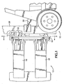
- a clamp assembly 10 is attached to the front of a fork lift truck 12.
- a base 14 supports a rotatable frame 16, to which are attached a pair of long clamp arms 18 and a pair of short clamp arms 20.
- a bidirectional rotary hydraulic motor 22 rotates frame 16 by driving a pinion gear 24 with a conventional worm drive assembly (not shown), the pinion gear 24 engaging the interior of a ring gear 16a (FIG. 3) on the frame 16.
- a bidirectional linear hydraulic cylinder could serve as the motor to drive the pinion gear 24 through a toothed rack or chain.
- Respective sets of hydraulic cylinders 26, 27 open and close clamp arms 18 and 20.
- a lifting mast 28 selectively lifts assembly 10, and is selectively tiltable forwardly and rearwardly by tilt cylinders such as 29.
- Clamp assembly 10 is specifically adapted to the handling of paper rolls. It is important, in this application, to rotate clamp arms 18 and 20 into the upright position shown in FIG. 1 so that paper rolls may be picked up or set down in a precisely upright position without edge damage. It is also important to rotate frame 16 into the precisely horizontal position shown in FIG. 2 to pick up and set down paper rolls in the horizontal position without edge damage. In addition, it is important to be able to rotate frame 16 180° from the upright position shown in FIG. 1, so that upright paper rolls which are located close to walls or other obstacles may be engaged with short clamp arms 20 adjacent to such wall or obstacle, regardless of whether located on the right or left side of the paper roll, to facilitate engagement of the roll.
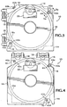
- triggering assembly which is part of an automatic rotation control system.
- Such triggering assembly preferably has a rotation-stopping switch 40a and a rotation-slowing switch 42a mounted by a switch bracket 44 to base 14.
- Rotation-stopping switch 40a is actuated by three triggering devices in the form of cams 40b, 40c and 40d, spaced 90° apart on the rotatable frame 16 for positioning clamp arms 18 and 20 at a horizontal position and at either one of the two possible upright positions.
- rotation-slowing switch 42a is actuated by three triggering devices in the form of cams 42b, 42c and 42d, spaced 90° apart.
- Switch 42a slows down the movement of frame 16 in a range about both sides of each stopping position to avoid shock-loading the system when switch 40a stops the movement of frame 16.
- triggering devices such as magnetic or optical proximity triggering devices.
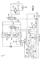
- the hydraulic circuit 46 of assembly 10 includes a bidirectional manually-controlled hydraulic valve 50 that can rotate the hydraulic motor 22 in a first or second direction depending on the position of manually-controlled hydraulic valve 50, thus rotating the frame 16 to any position in a 360° range.
- motor 22 rotates frame 16 until rotation-slowing switch 42a of the automatic rotation control system is depressed by cam 42b, 42c or 42d, as shown with respect to cam 42d in FIGS. 6a and 6b.
- This closes a normally open rotation-slowing contact 60, permitting current to flow from a DC power source 61 through a normally closed relay switch 88a and a solenoid 62 of a rotation-slowing electrically activated hydraulic valve 64.
- This shuts off the flow of hydraulic fluid through valve 64 so that the hydraulic fluid flowing through the motor 22, regardless of its direction of rotation, must flow through a hydraulic flow restrictor 66, thereby slowing hydraulic motor 22.
- valve 82 When rotation-stopping switch 40a is thereafter depressed by cam 40d as shown in FIGS. 5a and 5b, normally open rotation-stopping contact 78 is closed, permitting current to flow through a normally closed relay switch 88b and the solenoid 80 of a rotation-stopping electrically activated hydraulic valve 82.
- the resulting actuation of valve 82 switches the hydraulic pilot pressure normally applied to the downstream counterbalance valve 84a or 84b (depending on the direction of rotation) from a high pressure, which normally holds the downstream valve 84a or 84b open during actuation of the valve 50, to a low pressure which closes the downstream valve 84a or 84b. This causes motor 22 to stop because fluid flow through the motor is blocked by the closure of valve 84a or 84b.
- Timed dual relay 88 permits rotation of frame 16 to resume automatically after frame 16 has been slowed or stopped for about five seconds. This permits an operator to stop automatically at a stop point, pick up or set down a paper roll, and then resume rotation without having to override the automatic rotation control system manually. After rotation-slowing contact 60 has been switched closed for about 5 seconds, the magnetic field of winding 88c of the relay 88 will have developed sufficient field strength to cause relay switches 88a and 88b to open, thereby interrupting the flow of current through the solenoid valves 64 and 82 and restoring them to their normally unactuated conditions so that the motor 22 is controlled solely in response to manually-controlled valve 50.
- valve 50 rotates the motor 22 from the stop position, resulting in the opening of contacts 60 and 78 and the de-energizing of winding 88c, which permits relay switches 88a and 88b to return to their normally closed conditions in preparation for the approach of the next stop position.
- override button 92b Mounted on the manual control handle 92a of manual control valve 50 is an override button 92b, which alternatively permits the manual override of the automatic rotation control system.
- override button 92b When override button 92b is depressed, the.power source 61 is disconnected, thereby disabling the automatic rotation control system and allowing unrestricted rotation of the frame 16 through any stop position in any direction before any stopping occurs.
- the assembly just described has a number of significant advantages over the prior art. Principally, without the need for expensive and delicate computerized controls, it can rotate 180° between a first precise upright stop position and an inverted second precise upright stop position, and it can also stop at a precisely horizontal position. As a result, it can precisely engage or deposit a horizontal paper roll or an upright paper roll, whether it is more easily manipulated in the first or second upright position. It can also selectively rotate it into the horizontal position, or into an inverted horizontal position, for movement by the lift truck and placement onto a paper dispensing apparatus with the proper unwinding orientation. Also, it can be canted with respect to any stop position in either rotational direction, so that the paper roll may be engaged or deposited in a proper attitude even if the lift truck is travelling obliquely along a loading ramp.
- override button 92b allows frame 16 to be rotated without interruption past any of the cam stop positions, so that the operator need not be delayed by having the frame stop.
- dual relay 88 permits an operator to rotate frame 16 to a desired cam stop position, engage or disengage a paper roll and then resume rotation of frame 16 without needing to manually override the automatic rotation control system.
Landscapes
- Engineering & Computer Science (AREA)
- Transportation (AREA)
- Structural Engineering (AREA)
- Civil Engineering (AREA)
- Life Sciences & Earth Sciences (AREA)
- Geology (AREA)
- Mechanical Engineering (AREA)
- Forklifts And Lifting Vehicles (AREA)
- Load-Engaging Elements For Cranes (AREA)
- Replacement Of Web Rolls (AREA)
Priority Applications (1)
| Application Number | Priority Date | Filing Date | Title |
|---|---|---|---|
| EP05008044A EP1555239A3 (en) | 1997-10-24 | 1998-10-15 | Clamp assembly with automatic rotation control |
Applications Claiming Priority (2)
| Application Number | Priority Date | Filing Date | Title |
|---|---|---|---|
| US08/956,695 US5927932A (en) | 1997-10-24 | 1997-10-24 | Clamp assembly with automatic rotation control |
| US956695 | 1997-10-24 |
Related Child Applications (1)
| Application Number | Title | Priority Date | Filing Date |
|---|---|---|---|
| EP05008044A Division EP1555239A3 (en) | 1997-10-24 | 1998-10-15 | Clamp assembly with automatic rotation control |
Publications (3)
| Publication Number | Publication Date |
|---|---|
| EP0911295A2 EP0911295A2 (en) | 1999-04-28 |
| EP0911295A3 EP0911295A3 (en) | 2000-12-20 |
| EP0911295B1 true EP0911295B1 (en) | 2005-07-06 |
Family
ID=25498562
Family Applications (2)
| Application Number | Title | Priority Date | Filing Date |
|---|---|---|---|
| EP98308460A Expired - Lifetime EP0911295B1 (en) | 1997-10-24 | 1998-10-15 | Clamp assembly with automatic rotation control |
| EP05008044A Withdrawn EP1555239A3 (en) | 1997-10-24 | 1998-10-15 | Clamp assembly with automatic rotation control |
Family Applications After (1)
| Application Number | Title | Priority Date | Filing Date |
|---|---|---|---|
| EP05008044A Withdrawn EP1555239A3 (en) | 1997-10-24 | 1998-10-15 | Clamp assembly with automatic rotation control |
Country Status (6)
| Country | Link |
|---|---|
| US (1) | US5927932A (enExample) |
| EP (2) | EP0911295B1 (enExample) |
| JP (1) | JPH11209090A (enExample) |
| CA (1) | CA2247344C (enExample) |
| DE (1) | DE69830773T8 (enExample) |
| FI (1) | FI982202L (enExample) |
Families Citing this family (17)
| Publication number | Priority date | Publication date | Assignee | Title |
|---|---|---|---|---|
| DE29903671U1 (de) * | 1999-03-02 | 1999-08-05 | Westfalia-WST-Systemtechnik GmbH & Co. KG, 33829 Borgholzhausen | Regalfahrzeug |
| DE10013359A1 (de) * | 2000-03-20 | 2001-10-04 | Meyer Hans H Gmbh | Hublader oder Anbaugerät für einen Hublader mit einem Drehgerät |
| CA2480376C (en) * | 2003-09-04 | 2013-04-09 | Justoy Pty Ltd | Article handling apparatus |
| US8403618B2 (en) * | 2004-11-30 | 2013-03-26 | Cascade Corporation | Lift truck load handler |
| DE102006014532A1 (de) * | 2006-03-29 | 2007-10-11 | Koenig & Bauer Aktiengesellschaft | Vorrichtung zur Förderung einer oder mehrerer Materialrollen mit einem Transportsystem und einer Rollengreifeinrichtung zur Aufnahme der Materialrolle |
| US7780397B1 (en) | 2007-06-14 | 2010-08-24 | Coastal Cargo Company, Inc. | Method and apparatus for loading vessels using rotation |
| US8777549B2 (en) * | 2011-06-24 | 2014-07-15 | Honda Motor Co., Ltd. | Die rotation system and method |
| US8568079B2 (en) | 2012-02-15 | 2013-10-29 | Cascade Corporation | Rotator braking system for a lift truck load handler |
| US10087958B2 (en) | 2012-04-19 | 2018-10-02 | Cascade Corporation | Fluid power control system for mobile load handling equipment |
| CN102806281B (zh) * | 2012-09-13 | 2015-04-01 | 上海第二工业大学 | 一种不规则管料自动提升定位夹紧装置 |
| US9290367B2 (en) * | 2013-06-17 | 2016-03-22 | Cascade Corporation | Tissue roll-handling clamp |
| US9309099B2 (en) | 2014-06-20 | 2016-04-12 | Cascade Corporation | Side-shift limiter |
| DE202015008406U1 (de) | 2015-12-05 | 2016-01-12 | Durwen Maschinenbau Gmbh | Anbaugerät für Gabelstapler mit drehbaren lastaufnehmenden Vorrichtungen |
| CN107337079B (zh) * | 2017-07-31 | 2018-09-28 | 无锡康柏斯机械科技有限公司 | 一种内套绳索式卡环夹具装置 |
| WO2019092682A1 (en) * | 2017-11-13 | 2019-05-16 | Nhon Hoa Nguyen | Lifting cart for building construction |
| CN108996438B (zh) * | 2018-08-01 | 2020-05-15 | 阜阳市棋剑节能环保设备有限公司 | 一种便于对物体进行固定的叉车前叉 |
| US12304790B1 (en) | 2021-07-20 | 2025-05-20 | Shaw Industries Group, Inc. | Clamp adapter for lift vehicle to facilitate lifting of malleable objects |
Family Cites Families (16)
| Publication number | Priority date | Publication date | Assignee | Title |
|---|---|---|---|---|
| US2287469A (en) * | 1941-04-09 | 1942-06-23 | Elwell Parker Electric Co | Industrial truck |
| US2541268A (en) * | 1949-04-13 | 1951-02-13 | Mercury Mfg Co | Rotating fork carriage |
| US2754018A (en) * | 1953-07-13 | 1956-07-10 | Yale & Towne Mfg Co | Hydraulic power lines for industrial truck |
| US2984985A (en) * | 1959-02-16 | 1961-05-23 | Macmillin Hydraulic Engineerin | Hydraulic operating and control system |
| US3179274A (en) * | 1962-09-28 | 1965-04-20 | Allis Chalmers Mfg Co | Control system for lift truck attachment |
| US3426927A (en) * | 1968-02-12 | 1969-02-11 | Cyril Horace Tracey Woodward | Movable platform with lift and turnover mechanism |
| DE2442865C3 (de) * | 1974-09-06 | 1979-07-05 | Hagenuk Vormals Neufeldt & Kuhnke Gmbh, 2300 Kiel | Vorrichtung, insbesondere Manipulator, zum raschen Bewegen und genauen Positionieren eines Laststellglieds längs eines vorgegebenen Weges |
| US4161256A (en) * | 1977-10-04 | 1979-07-17 | Cascade Corporation | Fluid power system having multiple, separately controllable double-acting fluid motors and reduced number of fluid conduits |
| US4177000A (en) * | 1978-03-22 | 1979-12-04 | Cascade Corporation | Rotatable load clamp adapted for selective load positioning in response to selective rotational positioning of clamp |
| JPS60186271A (ja) * | 1984-02-15 | 1985-09-21 | 日本たばこ産業株式会社 | リ−ル供給装置におけるストツカ− |
| US4597710A (en) * | 1984-11-28 | 1986-07-01 | Athey Products Corporation | Trash collection vehicle side-loading apparatus |
| US4742468A (en) * | 1986-06-16 | 1988-05-03 | Yamate Industrial Co., Ltd. | Lift truck control system |
| US5281076A (en) * | 1991-05-08 | 1994-01-25 | Liberty Diversified Industries | Forklift attachment |
| JPH05238692A (ja) * | 1992-02-27 | 1993-09-17 | Mitsubishi Heavy Ind Ltd | フォークリフトの制御装置 |
| JPH05238685A (ja) * | 1992-02-28 | 1993-09-17 | Mitsubishi Heavy Ind Ltd | フォークリフトの制御装置 |
| US5536133A (en) * | 1995-02-10 | 1996-07-16 | Long Reach Holdings, Inc. | Pivot frame roll clamp assembly for attachment to a lift truck |
-
1997
- 1997-10-24 US US08/956,695 patent/US5927932A/en not_active Expired - Lifetime
-
1998
- 1998-09-16 CA CA002247344A patent/CA2247344C/en not_active Expired - Fee Related
- 1998-10-09 FI FI982202A patent/FI982202L/fi unknown
- 1998-10-15 EP EP98308460A patent/EP0911295B1/en not_active Expired - Lifetime
- 1998-10-15 EP EP05008044A patent/EP1555239A3/en not_active Withdrawn
- 1998-10-15 DE DE69830773T patent/DE69830773T8/de not_active Expired - Fee Related
- 1998-10-26 JP JP10303986A patent/JPH11209090A/ja active Pending
Also Published As
| Publication number | Publication date |
|---|---|
| JPH11209090A (ja) | 1999-08-03 |
| CA2247344C (en) | 2001-01-09 |
| EP1555239A2 (en) | 2005-07-20 |
| CA2247344A1 (en) | 1999-04-24 |
| DE69830773D1 (de) | 2005-08-11 |
| DE69830773T2 (de) | 2006-04-27 |
| DE69830773T8 (de) | 2006-08-24 |
| FI982202A7 (fi) | 1999-04-25 |
| EP0911295A2 (en) | 1999-04-28 |
| EP0911295A3 (en) | 2000-12-20 |
| FI982202L (fi) | 1999-04-25 |
| EP1555239A3 (en) | 2005-10-26 |
| US5927932A (en) | 1999-07-27 |
| FI982202A0 (fi) | 1998-10-09 |
Similar Documents
| Publication | Publication Date | Title |
|---|---|---|
| EP0911295B1 (en) | Clamp assembly with automatic rotation control | |
| US5536133A (en) | Pivot frame roll clamp assembly for attachment to a lift truck | |
| EP0575045B1 (en) | Hoist machine | |
| US5088879A (en) | Forward tilt limit system for lift trucks | |
| JP3656319B2 (ja) | フォークリフトのティルト制御装置 | |
| WO2018231134A1 (en) | A clamping device for a forklift and a forklift having such a clamping device | |
| JP2576369Y2 (ja) | 車載クレーンのフツク格納装置 | |
| JPS6136553Y2 (enExample) | ||
| JP4942575B2 (ja) | 建設機械のデセル装置 | |
| JPH0530096U (ja) | 作業車両における旋回台の規制装置 | |
| JP3240321B2 (ja) | コンバイン | |
| JP2797948B2 (ja) | コンテナスプレッダ装置 | |
| JPH0338489Y2 (enExample) | ||
| JPS5825773Y2 (ja) | 刈高さ自動制御装置 | |
| US20010024610A1 (en) | Lift truck or an attachment for a lift truck incorporating a rotating device | |
| JP3900665B2 (ja) | 産業車両の油圧制御装置 | |
| JPH0543038Y2 (enExample) | ||
| JP2556165Y2 (ja) | ブームを有する作業機の安全装置 | |
| JPH0642272Y2 (ja) | フォークリフトの荷役操作装置 | |
| JPS5844017Y2 (ja) | イドウノウキニオケル クラツチセイギヨソウチ | |
| JPH0637639Y2 (ja) | コンバインのロ−リング装置用操作構造 | |
| JPH11106197A (ja) | フォークリフトの荷役レバー装置 | |
| JPH02110719A (ja) | 複合操作レバー構造 | |
| KR100187088B1 (ko) | 트럭의 적재함 하강 방지용 안전블록장치 | |
| JPH0333211Y2 (enExample) |
Legal Events
| Date | Code | Title | Description |
|---|---|---|---|
| PUAI | Public reference made under article 153(3) epc to a published international application that has entered the european phase |
Free format text: ORIGINAL CODE: 0009012 |
|
| AK | Designated contracting states |
Kind code of ref document: A2 Designated state(s): DE FI GB IT SE |
|
| AX | Request for extension of the european patent |
Free format text: AL;LT;LV;MK;RO;SI |
|
| PUAL | Search report despatched |
Free format text: ORIGINAL CODE: 0009013 |
|
| AK | Designated contracting states |
Kind code of ref document: A3 Designated state(s): AT BE CH CY DE DK ES FI FR GB GR IE IT LI LU MC NL PT SE |
|
| AX | Request for extension of the european patent |
Free format text: AL;LT;LV;MK;RO;SI |
|
| RIC1 | Information provided on ipc code assigned before grant |
Free format text: 7B 66F 9/18 A, 7B 66F 9/12 B |
|
| 17P | Request for examination filed |
Effective date: 20010430 |
|
| AKX | Designation fees paid |
Free format text: DE FI GB IT SE |
|
| 17Q | First examination report despatched |
Effective date: 20040308 |
|
| GRAP | Despatch of communication of intention to grant a patent |
Free format text: ORIGINAL CODE: EPIDOSNIGR1 |
|
| GRAS | Grant fee paid |
Free format text: ORIGINAL CODE: EPIDOSNIGR3 |
|
| GRAA | (expected) grant |
Free format text: ORIGINAL CODE: 0009210 |
|
| AK | Designated contracting states |
Kind code of ref document: B1 Designated state(s): DE FI GB IT SE |
|
| REG | Reference to a national code |
Ref country code: GB Ref legal event code: FG4D |
|
| REF | Corresponds to: |
Ref document number: 69830773 Country of ref document: DE Date of ref document: 20050811 Kind code of ref document: P |
|
| REG | Reference to a national code |
Ref country code: SE Ref legal event code: TRGR |
|
| PLBE | No opposition filed within time limit |
Free format text: ORIGINAL CODE: 0009261 |
|
| STAA | Information on the status of an ep patent application or granted ep patent |
Free format text: STATUS: NO OPPOSITION FILED WITHIN TIME LIMIT |
|
| 26N | No opposition filed |
Effective date: 20060407 |
|
| PGFP | Annual fee paid to national office [announced via postgrant information from national office to epo] |
Ref country code: DE Payment date: 20071130 Year of fee payment: 10 |
|
| PGFP | Annual fee paid to national office [announced via postgrant information from national office to epo] |
Ref country code: FI Payment date: 20071030 Year of fee payment: 10 Ref country code: IT Payment date: 20071029 Year of fee payment: 10 |
|
| PGFP | Annual fee paid to national office [announced via postgrant information from national office to epo] |
Ref country code: SE Payment date: 20071029 Year of fee payment: 10 |
|
| PGFP | Annual fee paid to national office [announced via postgrant information from national office to epo] |
Ref country code: GB Payment date: 20071029 Year of fee payment: 10 |
|
| EUG | Se: european patent has lapsed | ||
| GBPC | Gb: european patent ceased through non-payment of renewal fee |
Effective date: 20081015 |
|
| PG25 | Lapsed in a contracting state [announced via postgrant information from national office to epo] |
Ref country code: FI Free format text: LAPSE BECAUSE OF NON-PAYMENT OF DUE FEES Effective date: 20081015 |
|
| PG25 | Lapsed in a contracting state [announced via postgrant information from national office to epo] |
Ref country code: IT Free format text: LAPSE BECAUSE OF NON-PAYMENT OF DUE FEES Effective date: 20081015 Ref country code: DE Free format text: LAPSE BECAUSE OF NON-PAYMENT OF DUE FEES Effective date: 20090501 |
|
| PG25 | Lapsed in a contracting state [announced via postgrant information from national office to epo] |
Ref country code: GB Free format text: LAPSE BECAUSE OF NON-PAYMENT OF DUE FEES Effective date: 20081015 |
|
| PG25 | Lapsed in a contracting state [announced via postgrant information from national office to epo] |
Ref country code: SE Free format text: LAPSE BECAUSE OF NON-PAYMENT OF DUE FEES Effective date: 20081016 |