EP0907043B1 - Dispositif de commande de pontage d'un convertisseur de couple - Google Patents
Dispositif de commande de pontage d'un convertisseur de couple Download PDFInfo
- Publication number
- EP0907043B1 EP0907043B1 EP98118572A EP98118572A EP0907043B1 EP 0907043 B1 EP0907043 B1 EP 0907043B1 EP 98118572 A EP98118572 A EP 98118572A EP 98118572 A EP98118572 A EP 98118572A EP 0907043 B1 EP0907043 B1 EP 0907043B1
- Authority
- EP
- European Patent Office
- Prior art keywords
- lock
- shift
- torque
- accelerator pedal
- decision
- Prior art date
- Legal status (The legal status is an assumption and is not a legal conclusion. Google has not performed a legal analysis and makes no representation as to the accuracy of the status listed.)
- Expired - Lifetime
Links
- 230000003321 amplification Effects 0.000 claims description 21
- 238000003199 nucleic acid amplification method Methods 0.000 claims description 21
- 238000009825 accumulation Methods 0.000 claims description 11
- SAZUGELZHZOXHB-UHFFFAOYSA-N acecarbromal Chemical compound CCC(Br)(CC)C(=O)NC(=O)NC(C)=O SAZUGELZHZOXHB-UHFFFAOYSA-N 0.000 claims 1
- 230000001133 acceleration Effects 0.000 description 11
- 230000000694 effects Effects 0.000 description 10
- 230000005540 biological transmission Effects 0.000 description 9
- 238000000034 method Methods 0.000 description 7
- 102100022907 Acrosin-binding protein Human genes 0.000 description 4
- 102100035167 Coiled-coil domain-containing protein 54 Human genes 0.000 description 3
- 239000000446 fuel Substances 0.000 description 3
- 238000001514 detection method Methods 0.000 description 2
- 230000000717 retained effect Effects 0.000 description 2
- 230000003213 activating effect Effects 0.000 description 1
- 230000000994 depressogenic effect Effects 0.000 description 1
- 238000010586 diagram Methods 0.000 description 1
Images


Classifications
-
- F—MECHANICAL ENGINEERING; LIGHTING; HEATING; WEAPONS; BLASTING
- F16—ENGINEERING ELEMENTS AND UNITS; GENERAL MEASURES FOR PRODUCING AND MAINTAINING EFFECTIVE FUNCTIONING OF MACHINES OR INSTALLATIONS; THERMAL INSULATION IN GENERAL
- F16H—GEARING
- F16H61/00—Control functions within control units of change-speed- or reversing-gearings for conveying rotary motion ; Control of exclusively fluid gearing, friction gearing, gearings with endless flexible members or other particular types of gearing
- F16H61/14—Control of torque converter lock-up clutches
- F16H61/143—Control of torque converter lock-up clutches using electric control means
-
- F—MECHANICAL ENGINEERING; LIGHTING; HEATING; WEAPONS; BLASTING
- F16—ENGINEERING ELEMENTS AND UNITS; GENERAL MEASURES FOR PRODUCING AND MAINTAINING EFFECTIVE FUNCTIONING OF MACHINES OR INSTALLATIONS; THERMAL INSULATION IN GENERAL
- F16H—GEARING
- F16H61/00—Control functions within control units of change-speed- or reversing-gearings for conveying rotary motion ; Control of exclusively fluid gearing, friction gearing, gearings with endless flexible members or other particular types of gearing
- F16H2061/0075—Control functions within control units of change-speed- or reversing-gearings for conveying rotary motion ; Control of exclusively fluid gearing, friction gearing, gearings with endless flexible members or other particular types of gearing characterised by a particular control method
- F16H2061/0096—Control functions within control units of change-speed- or reversing-gearings for conveying rotary motion ; Control of exclusively fluid gearing, friction gearing, gearings with endless flexible members or other particular types of gearing characterised by a particular control method using a parameter map
-
- F—MECHANICAL ENGINEERING; LIGHTING; HEATING; WEAPONS; BLASTING
- F16—ENGINEERING ELEMENTS AND UNITS; GENERAL MEASURES FOR PRODUCING AND MAINTAINING EFFECTIVE FUNCTIONING OF MACHINES OR INSTALLATIONS; THERMAL INSULATION IN GENERAL
- F16H—GEARING
- F16H59/00—Control inputs to control units of change-speed- or reversing-gearings for conveying rotary motion
- F16H59/14—Inputs being a function of torque or torque demand
- F16H59/18—Inputs being a function of torque or torque demand dependent on the position of the accelerator pedal
-
- F—MECHANICAL ENGINEERING; LIGHTING; HEATING; WEAPONS; BLASTING
- F16—ENGINEERING ELEMENTS AND UNITS; GENERAL MEASURES FOR PRODUCING AND MAINTAINING EFFECTIVE FUNCTIONING OF MACHINES OR INSTALLATIONS; THERMAL INSULATION IN GENERAL
- F16H—GEARING
- F16H59/00—Control inputs to control units of change-speed- or reversing-gearings for conveying rotary motion
- F16H59/36—Inputs being a function of speed
- F16H59/44—Inputs being a function of speed dependent on machine speed, e.g. the vehicle speed
-
- F—MECHANICAL ENGINEERING; LIGHTING; HEATING; WEAPONS; BLASTING
- F16—ENGINEERING ELEMENTS AND UNITS; GENERAL MEASURES FOR PRODUCING AND MAINTAINING EFFECTIVE FUNCTIONING OF MACHINES OR INSTALLATIONS; THERMAL INSULATION IN GENERAL
- F16H—GEARING
- F16H59/00—Control inputs to control units of change-speed- or reversing-gearings for conveying rotary motion
- F16H59/74—Inputs being a function of engine parameters
Definitions
- This invention relates to lock-up control devices that control lock-up clutches provided in power transmission systems of cars equipped with automatic gears.
- This application is based on Patent Application No. Hei JP 9-269060 A (& EP 798496 A).
- the power transmission system of the car uses both of a torque converter and a lock-up clutch so as to improve power transmission efficiency.
- the conventional lock-up control device provided for the power transmission system of the car, is designed to use torque amplification effect of the torque converter (or deceleration effect) by adjusting engagement force of the lock-up clutch in response to situation in revolutions of the engine.
- the paper of Japanese Patent Application, Publication No. Hei JP 9-32915 A discloses an example of the lock-up control device, which is designed as follows:
- the lock-up control device Based on depression of an accelerator pedal, a decision is made as to whether a driver has an intention to accelerate the car or not. If the driver has such an intention to accelerate the car, the lock-up control device releases an engaged state of the lock-up clutch, so that the power transmission system is placed in a power transmission state using the torque converter.
- the lock-up control device is capable of using torque amplification effect of the torque converter for acceleration of the car.
- the above lock-up control device uses the torque amplification effect of the torque converter according to needs to improve acceleration performance of the car.
- the lock-up control device is capable of further improving the acceleration performance by adjusting deceleration ratio (or torque amplification ratio) of the torque converter based on variation ratio of engine load such that the engine can demonstrate the maximum driving force.
- a driver demands the car to make a high degree of acceleration corresponding to a high level of torque, which exceeds an amount of torque that is obtained by using the aforementioned torque amplification effect of the torque converter.
- acceleration performance of the car is greatly influenced by a manner to perform the shift-down operation.
- the shift-down operation is performed in response to two stages of decisions, which are adequately made in different procedures. According to a first procedure, the device makes a decision such that the shift-down operation is performed in accordance with a shift map, which shows optimum shift positions on the basis of the relationship between the throttle opening and car velocity.
- a difference is detected between target torque and maximum torque corresponding to the above shift position, so if the engine does not have a room to increase engine torque thereof, the device makes a decision to perform the shift-down operation.
- the aforementioned two stages of decisions will be referred to as a first decision using the shift map and a second decision based on excessive engine torque, for example.
- gear-change boundary lines are drawn on the shift map to indicate events that gear-shift operations are performed.
- the shift-down operation is not performed unless the present point on the map representing the present relationship between the throttle opening and car velocity crosses a certain gear-change boundary line.
- a lock-up control device is provided to control the engaging and release of a lock-up clutch, which is arranged in parallel with a torque converter to transmit driving force of an engine of a car.
- target driving force is calculated based on accelerator pedal opening and car velocity.
- a present shift position is detected using a shift map based on accelerator pedal opening, car velocity and engine speed.
- Target engine torque is calculated based on the target driving force and present shift position as well as a torque amplification ratio, which is detected when the torque converter is placed in a torque amplification state.
- a lock-up release instruction is issued under conditions that the torque converter is placed in the torque amplification state while the target engine torque is greater than a preset value, which is determined in advance based on a torque characteristic of the engine. Therefore, it is possible to provide the engine torque as maximally as possible while maintaining the present shift position. Thus, it is possible to obtain good fuel efficiency by limiting control in release of the engaging of the lock-up clutch as minimally as possible.
- the device makes a decision as to whether a shift-down operation is performed or not. Therefore, in the case where the car is short of the engine torque even when the amplification effect of the torque converter is used, the device instructs the car to automatically perform the shift-down operation. Thus, it is possible to demonstrate good drivability.
- accumulation is performed on the accelerator pedal opening under the condition that the target engine torque is greater than the preset value. So, a shift-down instruction is issued under the condition that an accumulated value of the accelerator pedal opening exceeds a threshold value in accumulation of the accelerator pedal opening.
- the accumulation of the accelerator pedal opening it is possible to certainly acknowledge an event that the driver continues his or her intention to accelerate the car. Only when the driver truly has the acceleration intention, the device instructs the car to perform the shift-down operation. Thus, it is possible to certainly avoid occurrence of the shift busy phenomenon.
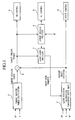
- FIG. 1 shows a configuration of a lock-up control device in accordance with the preferred embodiment of the invention.
- a target driving force calculation unit 1 performs calculations based on detection values of accelerator pedal manipulation value AP and car velocity V so as to produce target driving force (in other words, torque that an engine should generate) based on driver's intention to accelerate the car.
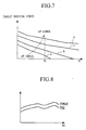
- the target driving force calculation unit 1 stores a map representing relationships (see FIG. 7) which are established between target driving forces and car velocities with respect to accelerator pedal openings respectively.
- FIG. 7 shows four characteristic curves, which are denoted by reference symbols of "a”, "b”, “c” and “d” respectively.
- accelerator pedal openings are sequentially increased as in an order of the characteristic curves a, b, c and d.
- a shift position calculation unit 2 stores a shift map representing relationships between the accelerator pedal openings AP and car velocities V as well as engine speeds NE. In addition, the shift position calculation unit 2 outputs a shift-down instruction based on a decision result of a shift-down decision unit 7, which will be described later.
- the target driving force and a shift position signal, which is output from the shift position calculation unit 2, are supplied to an arithmetic unit 3.
- the arithmetic unit 3 calculates "demanded" target engine torque based on the target driving force and a deceleration ratio corresponding to the shift position.
- the target engine torque calculated by the arithmetic unit 3 is supplied to a throttle control unit 4.
- the throttle control unit 4 outputs a throttle adjustment instruction, by which a throttle is controlled to have a throttle opening which will actualize the target engine torque.
- the target engine torque is supplied to a lock-up release decision unit 5 as well.
- the lock-up release decision unit 5 stores a table representing relationships between engine speed NE and utilizable engine torque TEX. Based on information of the engine speed NE and information of the utilizable engine torque TEX, the lock-up release decision unit 5 makes a decision as to whether the engine has a room to increase the engine torque up to the target engine torque or not.
- the lock-up release decision unit 5 stores data regarding torque ratios (or deceleration ratios) of the torque converter. So, the lock-up release decision unit 5 makes a decision as to whether the torque ratio of the torque converter, corresponding to engine speed which is established after the lock-up is released, is greater than "1" or not.
- the lock-up release decision unit 5 issues an instruction as to whether the lock-up is released or not on the basis of results of the aforementioned decisions.
- This instruction is supplied to a lock-up control unit 6.
- the lock-up control unit 6 supplies an actuator (e.g., hydraulic solenoid) operating the lock-up clutch with a control signal, by which a degree of engaging of the lock-up clutch is controlled in response to a car travel condition.
- the degree of engaging of the lock-up clutch is defined by a ratio between power transmission of the lock-up clutch and power transmission of the torque converter.
- the lock-up release decision unit 5 also supplies the actuator with a control signal to release the engaged state of the lock-up clutch.
- the target engine torque is supplied to a shift-down decision unit 7.
- the shift-down decision unit 7 makes a decision as to whether shift-down operation is demanded or not on the basis of the accelerator pedal opening AP and the target engine torque.
- the shift-down decision unit 7 determines that the shift-down operation should be performed, it outputs a shift-down instruction to the shift position calculation unit 2.
- the shift position calculation unit 2 produces a shift position signal based on the "present" shift position. Normally, the shift position signal represents a same shift position of the present shift position.
- the shift position calculation unit 2 produces a shift position signal representing a shift position, which is downed from the present shift position.
- the shift position signal is forwarded to a shift control unit 8.
- the shift control unit 8 outputs an instruction to drive a mechanism used for the shift-down operation.
- the lock-up release decision unit 5 (hereinafter, simply referred to as the unit 5) produces demanded turbine torque TTR based on the target driving force and present shift position.
- the unit 5 produces a tor-con slip ratio ETRX at the lock-up release timing on the basis of the demanded turbine torque TTR and an input shaft speed of the torque converter.
- it reads a torque ratio KTRX of the torque converter from a table, which is prepared in advance to represent relationships between the tor-con slip ratios and torque amplification ratios of the torque converter.
- KTRX of the torque converter from a table, which is prepared in advance to represent relationships between the tor-con slip ratios and torque amplification ratios of the torque converter.
- KTRX the torque ratio KTRX
- a maximum value of utilizable engine torque (TEX) at the present engine speed from a torque characteristic table, which is stored in advance on a ROM to represent relationships between the engine speed NE and engine torque TE.
- TEX utilizable engine torque
- the above utilizable engine torque TEX is lower than a preset value TEMAX, which is suited to the present engine speed.
- TEMAX corresponds to engine torque that can be output when the throttle is placed in a full open state at the present shift position. Normally, it is possible to obtain the best engine efficiency by using the utilizable engine torque TEX.
- step SP2 a decision is made as to whether both of inequalities of "KTRX>1" and "TTR>TEX" are established or not.
- the unit 5 makes a decision as to whether the torque converter is placed in a torque amplification range or not while making a decision as to whether the demanded engine torque is greater than the utilizable engine torque or not.
- the utilizable engine torque corresponds to torque that the engine imparts to a turbine shaft of the torque converter to provide "demanded” driving force. If a decision result is "NO”, the unit 5 transfers control to step SP3. If "YES”, it transfers control to step SP4.
- step SP3 the unit 5 clears a flag F_LCCUT which represents a message that the lock-up should be released. Then, it ends control thereof.
- step SP4 the unit 5 set "1" to the flag F_LCCUT. Then, it ends control thereof.
- the lock-up control unit 6 controls the actuator operating the lock-up clutch to release the engaging of the lock-up clutch.
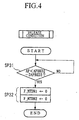
- step SP10 the shift-down decision unit 7 (hereinafter, simply referred to as the unit 7) makes a decision as to whether "1" is set to the flag F_LCCUT or not.
- the unit 7 transfers control to step SP11 only when a decision result is "YES”. If the decision result is "NO”, the unit does not perform shift-down control.
- step SP11 the unit 7 makes a decision as to whether "1" is set to a flag F_MTDN1 or not. Then, it transfers control to step SP12 when a decision result is "NO". If the decision result is "YES", it ends shift-down control.
- the flag F_MTDN1 cooperates with a flag F_MTDN2 to show which stage the shift-down control proceeds to. Conditions to set or reset those flags will be described later.
- step SP12 the unit 7 makes a decision as to whether the measured car velocity (V) is greater than downshift limit car velocity VMAX n-1 or not.
- the downshift limit car velocity VMAX n-1 corresponds to a lower shift position "n-1", which is lower than a present shift position "n”. Then, it transfers control to step SP13 when a decision result is "NO”. If the decision result is "YES”, it transfers control directly to step SP15.
- the aforementioned car velocity VMAX corresponds to data, which are determined based on mechanical performance of the change gear with regard to each of shift positions and are stored in advance in a prescribed storage area.
- step SP13 the unit 7 retrieves a preset value TEMAX from the table, which is stored in advance on the ROM to represent relationships between the engine speed NE and engine torque TE.
- the retrieved preset value TEMAX represents engine torque corresponding to the present engine speed.
- this present value TEMAX corresponds to engine torque that can be output at the present shift position n when the throttle control unit controls the throttle to be placed in a full open state.
- step SP14 the unit 7 makes a decision as to whether demanded engine torque TECMD, which is determined based on the accelerator pedal opening, is greater than the aforementioned preset value TEMAX or not. Then, it transfers control to step SP16 when TECMD is greater than TEMAX. If a decision result is "NO", it can be said that the engine has a room to increase the engine torque thereof, so that the shift-down operation is not required. In this case, the unit 7 transfers control to step SP15, wherein both of flags F_MTDN1 and F_MTDN2 are cleared.
- step SP16 the unit 7 makes a decision as to whether "1" is set to the flag F_MTDN2 or not. If a decision result is "NO”, the unit 7 transfers control to step SP17. If "YES”, it transfers control directly to step SP18.
- step SP17 the unit 7 substitutes prescribed values for various kinds of parameters respectively, which will be described below.
- the unit 7 substitutes a measured value "AP" of the accelerator pedal opening for an amount of accelerator pedal opening APBKD1 at the decision start timing.
- Threshold values are set for an amount of variations of accelerator pedal opening " ⁇ AP" as decision criterion for the shift-down control, wherein they are stored in the table, which is stored on the ROM in advance. That is, a threshold value DAPBKD1 is set as decision criterion for execution of the shift-down control, while a threshold value DAPBKD2 is set as decision criterion for release of the shift-down control. So, the unit 7 retrieves those threshold values from the table. In general, as the car velocity becomes large, the accelerator pedal opening required for acceleration becomes large as well, so the threshold value DAPBKD1 correspondingly becomes large.
- the unit 7 resets a count value cTXKD of a counter whose count value is increased every time the amount of variations of accelerator pedal opening ⁇ AP is varied in an increasing direction.
- the unit 7 clears the flag F_MTDN1 while "1" is set to the flag F_MTDN2.
- step SP18 a decision is made as to whether the amount of variations of accelerator pedal opening ⁇ AP is positive or not. Then, the unit 7 transfers control to step SP19 when a decision result is "YES”. If the decision result is "NO”, it is assumed that the driver has no intention to further depress the accelerator pedal for further acceleration. So, the unit 7 ends the shift-down control.
- step SP19 the unit 7 increases the aforementioned count value cTXKD of the counter by an increment.
- step SP20 a decision is made as to whether the count value cTXKD exceeds a threshold value LIMTXKD or not. Then, the unit 7 transfers control to step SP21 when a decision result is "YES". If the decision result is "NO”, it is assumed that the driver has less (or small) intention to increase the accelerator pedal opening, in other words, the driver has less (or small) intention to accelerate the car. So, the unit 7 ends the shift-down control.
- step SP21 the unit 7 performs comparison between the accelerator pedal opening AP and sum of threshold values APBKD1 and DAPBKD1, which are set as threshold values of the accelerator pedal opening for the start and execution of the shift-down control. If the accelerator pedal opening AP is greater than the above sum of the threshold values, the unit 7 transfers control to step SP22. If the accelerator pedal opening A is smaller than the sum of the threshold values, it is discriminated that the shift-down operation is not required, so the unit 7 ends the shift-down control. Namely, the unit 7 proceeds to step SP22 to execute the shift-down operation (or downshift) under the condition that the accelerator pedal opening AP is increased to be more than the threshold values of the accelerator pedal opening.
- APBKD1 and DAPBKD1 are set as threshold values of the accelerator pedal opening for the start and execution of the shift-down control.
- step SP22 the unit 7 sets each of parameters to execute the downshift, as follows:
- a value "SHIFT-1" is set to a parameter SHIFT representing the shift position. That is, "1" is subtracted from the parameter SHIFT representing the shift position, so that a new shift position which is one gear lower than the foregoing shift position is set to the parameter SHIFT.
- step SP11 retains the decision result of "YES” unless the flag F_MTDN1 is cleared. So, the shift position is retained to conform with "SHIFT-1" while the shift-down control is not performed.
- the accelerator pedal opening AP at execution of the downshift is set to APBKD2, which represents a release-decision-related amount of variations of accelerator pedal opening used for release decision.
- step SP31 comparison is made between the present accelerator pedal opening AP and a value which is produced by subtracting the release-decision-related threshold value DAPBKD2 from the release-decision-related amount of variations of accel pedal opening APBKD2. If it is detected that the present accelerator pedal opening AP becomes smaller than the above value, the device transfers control to step SP32. In step SP32, the device clears both of the flags F_MTDN1 and F_MTDN2. Thus, the device ends control at the state which enables the shift-down control based on the foregoing decision of the step SP11 shown in FIG. 3.
- the device automatically ends the control to stop accumulation of the accelerator pedal opening. If the accelerator pedal opening AP does not become smaller than the prescribed value, the device repeats the step SP31 without changing the aforementioned flags F_MTDN1 and F_MTDN2.
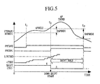
- TEMAX threshold value
- APBKD1 threshold value of accelerator pedal opening at time t1
- step SP19 the foregoing count value cTXKD is increased by an increment. In a duration that the accelerator pedal opening is held greater than the prescribed value, the count value cTXKD is increased continuously.
- the count value cTXKD exceeds the threshold value LIMTXKD in accumulation of the accelerator pedal opening.
- Such accumulation of the accelerator pedal opening can be actualized without using the special device and is performed using the software processing with ease.
- the count value cTXKD is not increased anymore.
- the device does not perform shift-down operation. In other words, the shift-down operation is performed only when the driver continues to hold his or her intention to accelerate the car.
- the present embodiment employs the accumulation of the accelerator pedal opening.
- the device counts a number of clock pulses after it is detected that the accelerator pedal opening exceeds a certain threshold value.
- a counted number represents elapsed time that elapses after the accelerator pedal is depressed by a predetermined value.
- Such a counted number can be used as an accumulated value of the accelerator pedal opening.
- the accumulation of the accelerator pedal opening can be performed by the software processing with ease.
- step SP21 If in step SP21, it is detected that the accelerator pedal opening AP exceeds the aforementioned threshold value TEMAX of accelerator pedal opening by the prescribed value DAPBKD1 or more, the device makes a decision that downshift should be performed.
- step SP22 "1" is set to the flag F_MTDN1, so that the downshift is executed.
- the change gear is placed in a shift hold state. Namely, in the case where the engine has no room to increase the engine torque thereof so that the shift-down operation is demanded, the device activates the shift-down operation under the condition that the driver continues to hold his or her intention to accelerate the car.
- the driver continues to hold his or her intention to accelerate the car.
- the device makes a decision that the shift-down operation should be performed only when the driver has strong intention to accelerate the car.
- the device transfers control to step SP32 based on the foregoing decision of the step SP31 (see FIG. 4).
- step SP32 the device clears both of the flags F_MTDN1 and F_MTDN2.
- the device is placed in a standby state to wait for a next time to perform shift-down control.
- the present embodiment performs shift-down control by using the detection value AP of the "actual" accelerator pedal opening.
- fuzzy estimation wherein travel environment of the car is estimated by the fuzzy control. So, it is possible to use an amount of accelerator pedal opening which is corrected based on the estimated travel environment of the car.
- the amount of accelerator pedal opening is multiplied by a coefficient to be greater than the actual accelerator pedal opening.
- the amount of accelerator pedal opening is multiplied by a coefficient to be smaller than the actual accelerator pedal opening.
- the shift-down control is performed using such a multiplied value of the accelerator pedal opening.
Landscapes
- Engineering & Computer Science (AREA)
- General Engineering & Computer Science (AREA)
- Mechanical Engineering (AREA)
- Control Of Transmission Device (AREA)
- Control Of Fluid Gearings (AREA)
Claims (3)
- Dispositif de commande de pontage qui commande la force d'engagement dans un embrayage de pontage agencé en parallèle avec un convertisseur de couple afin de transmettre la force d'entraínement d'un moteur, ledit dispositif de commande de pontage comprenant :caractérisé pardes moyens de commande de pontage (6) pour appliquer un signal de commande à un dispositif d'entraínement de l'embrayage de pontage afin d'exécuter l'engagement et le désengagement de l'embrayage de pontage ;des moyens de calcul de force d'entraínement cible (1) pour calculer la force d'entraínement cible d'une voiture sur la base de l'ouverture de la pédale d'accélérateur et de la vitesse de la voiture ;des moyens de détection de position de vitesse (2) pour détecter une position de vitesse actuelle ;des moyens de détermination d'état de convertisseur de couple pour prendre une décision quant à savoir si le convertisseur de couple se trouve dans un état d'amplification de couple ou non et pour détecter un rapport d'amplification de couple ;des moyens de calcul pour calculer le couple moteur cible sur la base de la force d'entraínement cible, de la position de vitesse actuelle et du rapport d'amplification de couple ;des moyens de comparaison (3) pour comparer le couple moteur cible avec une valeur prédéterminée qui est déterminée à l'avance à partir d'une caractéristique de couple ;
des moyens de décision de désengagement de pontage (5) pour émettre une instruction de désengagement de pontage vers les moyens de commande de pontage dans une condition où les moyens de comparaison déterminent que le couple moteur cible est supérieur à la valeur prédéterminée et les moyens de détermination d'état de convertisseur de couple déterminent que le convertisseur de couple se trouve dans l'état d'amplification de couple. - Dispositif de commande de pontage selon la revendication 1, comprenant, de plus, des moyens de décision de rétrogradation (7) pour prendre une décision quant à savoir si une opération de rétrogradation est effectuée ou non dans une condition où les moyens de décision de désengagement de pontage (5) émettent l'instruction de désengagement de pontage, de sorte que l'engagement de l'embrayage de pontage soit relâché.
- Dispositif de commande d'embrayage de pontage selon la revendication 2, dans lequel les moyens de décision de rétrogradation (7) effectuent un cumul de l'ouverture de la pédale d'accélérateur de manière à fournir une valeur cumulée de l'ouverture de la pédale d'accélérateur dans une condition où le couple moteur cible est supérieur à la valeur prédéterminée, de sorte que les moyens de décision de rétrogradation émettent une instruction de rétrogradation dans une condition où la valeur cumulée de l'ouverture de la pédale d'accélérateur dépasse une valeur de seuil de cumul de l'ouverture de la pédale d'accélérateur, qui est déterminée à l'avance.
Applications Claiming Priority (3)
| Application Number | Priority Date | Filing Date | Title |
|---|---|---|---|
| JP26906097A JP3580993B2 (ja) | 1997-10-01 | 1997-10-01 | ロックアップ制御装置 |
| JP269060/97 | 1997-10-01 | ||
| JP26906097 | 1997-10-01 |
Publications (2)
| Publication Number | Publication Date |
|---|---|
| EP0907043A1 EP0907043A1 (fr) | 1999-04-07 |
| EP0907043B1 true EP0907043B1 (fr) | 2001-12-12 |
Family
ID=17467106
Family Applications (1)
| Application Number | Title | Priority Date | Filing Date |
|---|---|---|---|
| EP98118572A Expired - Lifetime EP0907043B1 (fr) | 1997-10-01 | 1998-10-01 | Dispositif de commande de pontage d'un convertisseur de couple |
Country Status (5)
| Country | Link |
|---|---|
| US (1) | US6314357B1 (fr) |
| EP (1) | EP0907043B1 (fr) |
| JP (1) | JP3580993B2 (fr) |
| DE (1) | DE69802882T2 (fr) |
| TW (1) | TW421698B (fr) |
Cited By (1)
| Publication number | Priority date | Publication date | Assignee | Title |
|---|---|---|---|---|
| CN106838298A (zh) * | 2015-12-04 | 2017-06-13 | 株式会社斯巴鲁 | 车辆控制装置 |
Families Citing this family (28)
| Publication number | Priority date | Publication date | Assignee | Title |
|---|---|---|---|---|
| JP3696380B2 (ja) * | 1997-08-27 | 2005-09-14 | 本田技研工業株式会社 | シフトダウン制御装置 |
| DE19963564A1 (de) * | 1999-12-29 | 2001-07-05 | Bosch Gmbh Robert | System zur Einstellung einer Getriebeübersetzung bei einem in einem Kraftfahrzeug eingebauten Getriebe |
| JP2001330140A (ja) * | 2000-05-22 | 2001-11-30 | Toyota Motor Corp | 車両用クラッチの制御装置 |
| JP4119613B2 (ja) * | 2001-01-11 | 2008-07-16 | ジヤトコ株式会社 | 自動変速機のロックアップ制御装置 |
| US7604566B2 (en) * | 2007-03-02 | 2009-10-20 | Honda Motor Co., Ltd. | System and method of controlling a torque converter lockup clutch |
| US7854681B2 (en) * | 2007-04-30 | 2010-12-21 | Caterpillar Inc | System for controlling a machine with a continuously variable transmission |
| EP2202430B1 (fr) | 2007-10-22 | 2012-05-30 | Komatsu Ltd. | Dispositif et procédé de commande de transmission pour véhicule de travail |
| US8352138B2 (en) * | 2007-11-30 | 2013-01-08 | Caterpillar Inc. | Dynamic control system for continuously variable transmission |
| FR2933462B1 (fr) * | 2008-07-04 | 2010-07-30 | Inst Francais Du Petrole | Procede pour controler la phase de fermeture d'un embrayage d'un systeme de transmission robotisee automobile |
| DE102008043106A1 (de) * | 2008-10-23 | 2010-04-29 | Zf Friedrichshafen Ag | Verfahren zum Betreiben der Wandlerüberbrückungskupplung in einem Lastschaltgetriebe einer Arbeitsmaschine umfassend zumindest eine hydraulisch betätigbare Hubeinrichtung |
| DE102008043109A1 (de) * | 2008-10-23 | 2010-04-29 | Zf Friedrichshafen Ag | Verfahren zum Schließen der Wandlerüberbrückungskupplung in einem Lastschaltgetriebe einer Arbeitsmaschine |
| DE102008043105A1 (de) * | 2008-10-23 | 2010-04-29 | Zf Friedrichshafen Ag | Verfahren zum Betätigen einer Kupplung eines hydrodynamischen Drehmomentwandlers |
| DE102008043107A1 (de) * | 2008-10-23 | 2010-04-29 | Zf Friedrichshafen Ag | Verfahren zum Umsteuern der Fahrtrichtung eines Fahrzeugs |
| DE102008043108A1 (de) * | 2008-10-23 | 2010-04-29 | Zf Friedrichshafen Ag | Verfahren zum Betätigen einer Kupplung eines hydrodynamischen Drehmomentwandlers |
| DE102008043110A1 (de) * | 2008-10-23 | 2010-04-29 | Zf Friedrichshafen Ag | Verfahren zur Ansteuerung einer Überbrückungskupplung eines hydrodynamischen Drehmomentwandlers |
| JP4923079B2 (ja) | 2009-03-27 | 2012-04-25 | ジヤトコ株式会社 | 無段変速機及びその制御方法 |
| JP4923080B2 (ja) * | 2009-03-27 | 2012-04-25 | ジヤトコ株式会社 | 無段変速機及びその制御方法 |
| JP4779030B2 (ja) | 2009-03-27 | 2011-09-21 | ジヤトコ株式会社 | 無段変速機及びその制御方法 |
| JP5027179B2 (ja) | 2009-03-27 | 2012-09-19 | ジヤトコ株式会社 | 無段変速機及びその制御方法 |
| JP5428528B2 (ja) * | 2009-05-25 | 2014-02-26 | アイシン精機株式会社 | 車両制御装置 |
| JP4914467B2 (ja) | 2009-07-17 | 2012-04-11 | ジヤトコ株式会社 | 無段変速機及びその制御方法 |
| JP2014104874A (ja) * | 2012-11-28 | 2014-06-09 | Toyota Motor Corp | 走行制御装置 |
| JP5733293B2 (ja) * | 2012-11-28 | 2015-06-10 | トヨタ自動車株式会社 | 走行制御装置 |
| JP5633557B2 (ja) * | 2012-11-28 | 2014-12-03 | トヨタ自動車株式会社 | 走行制御装置 |
| CN104870230B (zh) * | 2013-06-28 | 2018-04-17 | 株式会社小松制作所 | 作业车辆及作业车辆的控制方法 |
| DE102014009732B4 (de) * | 2014-06-28 | 2023-12-07 | Mercedes-Benz Group AG | Verfahren zum Betrieb eines Kraftfahrzeugantriebsstrangs, der eine Wandlerüberbrückungskupplung und ein Automatikgetriebe aufweist |
| JP6797470B2 (ja) * | 2016-09-30 | 2020-12-09 | ダイハツ工業株式会社 | 変速機の制御装置 |
| US10428938B2 (en) | 2017-07-21 | 2019-10-01 | GM Global Technology Operations LLC | Method and system for controlling a vehicle propulsion system |
Family Cites Families (18)
| Publication number | Priority date | Publication date | Assignee | Title |
|---|---|---|---|---|
| DE3212091C2 (de) * | 1982-04-01 | 1994-07-28 | Volkswagen Ag | Verfahren zum Betrieb eines Antriebsaggregates für Fahrzeuge |
| JPS58200855A (ja) * | 1982-05-20 | 1983-11-22 | Nissan Motor Co Ltd | Vベルト式無段変速機の変速制御方法 |
| US4725951A (en) * | 1983-12-29 | 1988-02-16 | Nissan Motor Co., Ltd. | Control system for lock-up clutch in torque converter |
| JPS62103232A (ja) * | 1985-10-30 | 1987-05-13 | Diesel Kiki Co Ltd | クラツチ制御装置 |
| US5035308A (en) * | 1987-10-01 | 1991-07-30 | Mazda Motor Corporation | Lock-up control system for automatic transmission |
| JP2843609B2 (ja) * | 1989-09-09 | 1999-01-06 | ジャトコ株式会社 | ロックアップクラッチの作動制御装置 |
| JPH03249474A (ja) * | 1990-02-27 | 1991-11-07 | Mazda Motor Corp | 加速検出装置及びこれを用いた流体継手の締結力制御装置 |
| US5221261A (en) | 1990-04-12 | 1993-06-22 | Schneider (Usa) Inc. | Radially expandable fixation member |
| US5496227A (en) * | 1990-04-18 | 1996-03-05 | Hitachi, Ltd. | Torque control method and apparatus for internal combustion engine and motor vehicles employing the same |
| US5274553A (en) * | 1991-05-09 | 1993-12-28 | Eaton Corporation | Torque converter slip rate based skip power downshift control strategy |
| JP2710080B2 (ja) * | 1991-09-14 | 1998-02-10 | 本田技研工業株式会社 | 自動変速機のロックアップクラッチの制御装置 |
| JP3318945B2 (ja) | 1992-03-02 | 2002-08-26 | 株式会社日立製作所 | 自動車用制御装置、自動車制御システム及び自動車の制御方法 |
| JPH0694116A (ja) | 1992-09-08 | 1994-04-05 | Hitachi Ltd | 自動変速制御装置 |
| US5475590A (en) * | 1993-10-22 | 1995-12-12 | Ford Motor Company | Automatic transmission torque converter bypass clutch control using engine torque compensation |
| JPH08178054A (ja) * | 1994-12-26 | 1996-07-12 | Honda Motor Co Ltd | 自動車の制御装置 |
| JPH08200493A (ja) * | 1995-01-23 | 1996-08-06 | Nippon Soken Inc | 自動変速装置 |
| US5743829A (en) * | 1995-02-22 | 1998-04-28 | Honda Giken Kogyo Kabushiki Kaisha | Control system for vehicle automatic transmission |
| JP3127350B2 (ja) | 1995-07-20 | 2001-01-22 | 本田技研工業株式会社 | ロックアップクラッチの制御装置 |
-
1997
- 1997-10-01 JP JP26906097A patent/JP3580993B2/ja not_active Expired - Fee Related
-
1998
- 1998-09-28 TW TW087116097A patent/TW421698B/zh not_active IP Right Cessation
- 1998-09-30 US US09/163,016 patent/US6314357B1/en not_active Expired - Fee Related
- 1998-10-01 EP EP98118572A patent/EP0907043B1/fr not_active Expired - Lifetime
- 1998-10-01 DE DE69802882T patent/DE69802882T2/de not_active Expired - Fee Related
Cited By (2)
| Publication number | Priority date | Publication date | Assignee | Title |
|---|---|---|---|---|
| CN106838298A (zh) * | 2015-12-04 | 2017-06-13 | 株式会社斯巴鲁 | 车辆控制装置 |
| CN106838298B (zh) * | 2015-12-04 | 2018-10-09 | 株式会社斯巴鲁 | 车辆控制装置 |
Also Published As
| Publication number | Publication date |
|---|---|
| US6314357B1 (en) | 2001-11-06 |
| JPH11108175A (ja) | 1999-04-20 |
| EP0907043A1 (fr) | 1999-04-07 |
| DE69802882D1 (de) | 2002-01-24 |
| TW421698B (en) | 2001-02-11 |
| JP3580993B2 (ja) | 2004-10-27 |
| DE69802882T2 (de) | 2002-06-20 |
Similar Documents
| Publication | Publication Date | Title |
|---|---|---|
| EP0907043B1 (fr) | Dispositif de commande de pontage d'un convertisseur de couple | |
| USRE43857E1 (en) | Shift control apparatus for vehicular automatic transmission and method thereof | |
| US8014925B2 (en) | Control apparatus for automatic transmission for vehicle | |
| US5669850A (en) | Shift hunting prevention for an automatic transmission | |
| JP2576240B2 (ja) | 半自動変速装置の制御装置 | |
| US5685801A (en) | Cruise control overspeed reduction with automatic transmission | |
| US5778331A (en) | Kickdown delay in cruise control for automatic transmission | |
| JP3696380B2 (ja) | シフトダウン制御装置 | |
| JP4670208B2 (ja) | 車両の制御装置 | |
| JPH07239021A (ja) | 自動変速機の制御装置 | |
| JP4021003B2 (ja) | 自動変速機の変速制御装置 | |
| JP2000280794A (ja) | 自動変速機の制御装置 | |
| US7574295B2 (en) | Method for controlling automatic or automated transmission downshift used for power braking | |
| US20080085815A1 (en) | Method For Adapting An Operating Mode Of An Automatic Variable Speed Transmission | |
| JPH11101339A (ja) | ロックアップクラッチ制御装置 | |
| JP2005114040A (ja) | 車両の制御装置 | |
| JP2523451B2 (ja) | エンジンのスロツトル弁制御装置 | |
| JP2921261B2 (ja) | 車両用自動変速機の変速制御装置 | |
| JP2958580B2 (ja) | 車両用自動変速機の変速制御装置 | |
| JP2576241B2 (ja) | 有段変速機用自動クラッチの制御装置 | |
| JP2542344B2 (ja) | 自動車のパワ−プラント制御装置 | |
| JP4129714B2 (ja) | 自動変速機の変速制御装置 | |
| JPH07259975A (ja) | 車両用自動変速機の変速制御装置 | |
| JP4910298B2 (ja) | 自動変速機の変速制御装置 | |
| KR100250295B1 (ko) | 오르막 난조 방지 방법 |
Legal Events
| Date | Code | Title | Description |
|---|---|---|---|
| PUAI | Public reference made under article 153(3) epc to a published international application that has entered the european phase |
Free format text: ORIGINAL CODE: 0009012 |
|
| AK | Designated contracting states |
Kind code of ref document: A1 Designated state(s): DE FR GB |
|
| AX | Request for extension of the european patent |
Free format text: AL;LT;LV;MK;RO;SI |
|
| 17P | Request for examination filed |
Effective date: 19990616 |
|
| AKX | Designation fees paid |
Free format text: DE FR GB |
|
| GRAG | Despatch of communication of intention to grant |
Free format text: ORIGINAL CODE: EPIDOS AGRA |
|
| GRAG | Despatch of communication of intention to grant |
Free format text: ORIGINAL CODE: EPIDOS AGRA |
|
| GRAH | Despatch of communication of intention to grant a patent |
Free format text: ORIGINAL CODE: EPIDOS IGRA |
|
| 17Q | First examination report despatched |
Effective date: 20010315 |
|
| GRAH | Despatch of communication of intention to grant a patent |
Free format text: ORIGINAL CODE: EPIDOS IGRA |
|
| GRAA | (expected) grant |
Free format text: ORIGINAL CODE: 0009210 |
|
| AK | Designated contracting states |
Kind code of ref document: B1 Designated state(s): DE FR GB |
|
| RIN1 | Information on inventor provided before grant (corrected) |
Inventor name: SAITO, YOSHIHARU Inventor name: KON, TAKANORI |
|
| REG | Reference to a national code |
Ref country code: GB Ref legal event code: IF02 |
|
| REF | Corresponds to: |
Ref document number: 69802882 Country of ref document: DE Date of ref document: 20020124 |
|
| PLBE | No opposition filed within time limit |
Free format text: ORIGINAL CODE: 0009261 |
|
| STAA | Information on the status of an ep patent application or granted ep patent |
Free format text: STATUS: NO OPPOSITION FILED WITHIN TIME LIMIT |
|
| 26N | No opposition filed | ||
| PGFP | Annual fee paid to national office [announced via postgrant information from national office to epo] |
Ref country code: GB Payment date: 20031001 Year of fee payment: 6 |
|
| PGFP | Annual fee paid to national office [announced via postgrant information from national office to epo] |
Ref country code: FR Payment date: 20031003 Year of fee payment: 6 |
|
| PG25 | Lapsed in a contracting state [announced via postgrant information from national office to epo] |
Ref country code: GB Free format text: LAPSE BECAUSE OF NON-PAYMENT OF DUE FEES Effective date: 20041001 |
|
| GBPC | Gb: european patent ceased through non-payment of renewal fee |
Effective date: 20041001 |
|
| PG25 | Lapsed in a contracting state [announced via postgrant information from national office to epo] |
Ref country code: FR Free format text: LAPSE BECAUSE OF NON-PAYMENT OF DUE FEES Effective date: 20050630 |
|
| REG | Reference to a national code |
Ref country code: FR Ref legal event code: ST |
|
| PGFP | Annual fee paid to national office [announced via postgrant information from national office to epo] |
Ref country code: DE Payment date: 20060928 Year of fee payment: 9 |
|
| PG25 | Lapsed in a contracting state [announced via postgrant information from national office to epo] |
Ref country code: DE Free format text: LAPSE BECAUSE OF NON-PAYMENT OF DUE FEES Effective date: 20080501 |