EP0906734B1 - Schmuckstückverschluss - Google Patents
Schmuckstückverschluss Download PDFInfo
- Publication number
- EP0906734B1 EP0906734B1 EP98116603A EP98116603A EP0906734B1 EP 0906734 B1 EP0906734 B1 EP 0906734B1 EP 98116603 A EP98116603 A EP 98116603A EP 98116603 A EP98116603 A EP 98116603A EP 0906734 B1 EP0906734 B1 EP 0906734B1
- Authority
- EP
- European Patent Office
- Prior art keywords
- clasp
- connector receptacle
- case
- jewellery
- connector
- Prior art date
- Legal status (The legal status is an assumption and is not a legal conclusion. Google has not performed a legal analysis and makes no representation as to the accuracy of the status listed.)
- Expired - Lifetime
Links
Images


Classifications
-
- A—HUMAN NECESSITIES
- A44—HABERDASHERY; JEWELLERY
- A44C—PERSONAL ADORNMENTS, e.g. JEWELLERY; COINS
- A44C5/00—Bracelets; Wrist-watch straps; Fastenings for bracelets or wrist-watch straps
- A44C5/18—Fasteners for straps, chains or the like
- A44C5/20—Fasteners for straps, chains or the like for open straps, chains or the like
- A44C5/2057—Fasteners locked by sliding or rotating of the male element of the fastener; Turn-button fasteners
- A44C5/2061—Fasteners locked by sliding or rotating of the male element of the fastener; Turn-button fasteners combined with spring means
Definitions
- the present invention relates to a jewelry lock according to the preamble of independent claim 1 and a method for closing jewelry, such as from the GB Patent 1,035,064 is known.
- Closure devices for jewelry are known. width Bayonet locks are widely used in the utility model DE Gm 76 01 893 described type Closure devices in particular allow one and the same Jewelry chain with different, decoratively designed To use closures.
- a closure is known with which a wear associated with the kinking of the chain at the lock should be prevented.
- the connector holder by means of a tilting bearing with an oval cross-section on this suitably shaped closure can be accommodated.
- the object of the present invention is a to create improved jewelry lock.
- the locking plug receptacle according to claim 1 with the bayonet-type connector attached to it the one that is taken when locking and secured against turning first position without further assistance from the wearer the movements of the chain on the clasp caused by wear axially move the acting low forces and slide axially freely into the positions in which twisting the plug connector is possible. So lies in Use a flat closure piece flat at any time, without fear of blocking its rotation.
- the closure of the invention is without can also be used with existing chains. It can also very thin chains like pearl or thin chains Gold chains are used without this having a minimum volume must have; use with thicker and therefore relatively rigid chains without the risk of wear and tear Bending of parts of the closure through the full page Enclosing the locking plug receptacle allows.
- the usage a small sleeve for gripping the locking plug holder ensures that the external dimensions of the invention Jewelery clasp only slightly larger than with conventional bayonet locks.
- This "floating Storage” is particularly desirable and is available with gap sizes of less than 2/10 mm, gap sizes preferably less than 5/100 mm and particularly preferably 2.5 / 100 mm, while the lock connector itself a length of a few Can have millimeters. It is preferred if the stroke, i.e. the immersion depth around which the locking plug receptacle yourself from the position range of the closure piece with free Rotation to the position secured against twisting in the Jack moves, also in the range of less than a millimeter lies. In a practical embodiment, so the same external dimensions as with common locking arrangements can be achieved according to the prior art.
- the socket in a practical version has an outer diameter of between 3 and 5 mm have what their problem-free Installation in beads, for example. It has proven to be beneficial proven if to achieve the small gap sizes the facing surfaces of the socket and plug connector generated by high-gloss turning.
- the low friction provided by the gap ensures even if the arrangement is free from wear Carrier of the chain while wearing the clasp plays and rotates it permanently.
- the the smooth rotatability even stimulates such play on.
- the wearer is irritated by standing up the lock is excluded when twisting the chain. On in this way the wearing comfort is increased.
- a piece of jewelry closure 1 includes at least one outside essentially cylindrical locking plug receptacle 2, which is designed to receive a locking plug 3, which on its side facing away from the jewelry clasp 1 can be connected with a chain 4 or the like or about penetrated in a known manner by a string of pearls is.
- grooves 5 are provided, which in the Use with projections 6a, 6b on the connector facing Side (reference number 7a on the double arrow A) of the locking plug receptacle 2 are arranged.
- Compression spring 9 on a plate 10 facing the plug, and presses them on the inside in the idle state of projections 6a, 6b and optionally an annular one Border around the cavity 8.
- the spring 9 On the opposite side (Reference number 7b on the double arrow) the spring 9 is supported an annular border.
- the locking plug receptacle 2 is in a socket 11 with at least essentially slidable hollow cylindrical interior and generally arranged concentrically and by a projection 12 on the side of the socket facing the plug (7a) 11 and opposite the socket bottom 16 held captive.
- the length of the bushing 11 compared to the length of the Lock plug receptacle 2 and thus the stroke by which the Lock plug receptacle 2 along the double arrow A in the Socket 11 can be moved is in the drawing for reasons the clarity of what is required in practice Exaggerated measure. It is sufficient if the socket 11 only is little longer than the locking plug receptacle 2, which in practice has a length measurement in the millimeter range.
- the locking connector receptacle 2 faces the connector 3 facing away (direction 7b) a recess 14 in which when positioning the locking plug receptacle 2 in a first position close to or directly on the socket bottom 16 (as shown in FIGS. 1 and 2a), one provided there corresponding increase 15 in positive and / or frictional Intervention can occur.
- the locking plug receptacle 2 Unless the locking plug receptacle 2 is not in the first Position close to or directly on the socket bottom 16, but away from it in any other axial position (Fig. 2b), which is in the stroke range, the locking plug receptacle turn freely in the socket.
- a gap 13 is provided, which is not to scale Drawing is shown exaggerated. In practice it is by the difference between the outer diameter of the plug connector 2 and clear width of the socket 11 formed Gap 13 very small; Gap sizes below half Millimeters are easy to manufacture, are preferred Gap sizes under 2/10 mm and a particularly favorable storage behavior results in gap sizes below 5/100 mm, preferred 2.5 / 100mm. With a sufficiently precise production is a smooth rotation of the locking plug receptacle 2 in the bushing 11 enables the ball bearing-like turning properties guaranteed. The for the small gap sizes mentioned required manufacturing precision can in particular by high-gloss turning of the parts on standard machines be achieved.
- the jewelry clasp according to the invention is closed, by the plug 3 past the projections 12 of the socket 11 is pressed onto the locking plug receptacle and the grooves 5 brought into alignment with the projections 6a, 6b.
- the Tip 3a of plug 3 is then in contact with the plate 10 pressed, which prevents jamming with the spring 9.
- the Pressing causes a movement of the locking plug receptacle 2 inside the socket 11 and leads to seating of the locking plug receptacle on the socket bottom 16, recess 14 and increase 15 if necessary by a slight rotary movement engage at connector 3.
- the breech's own gravity, Restoring forces of a somewhat rigid chain or the light ones Movements of the chain wearer are sufficient for this.
- the locking plug receptacle 2 can then be freely inside turn the socket 11 with the plug connected.
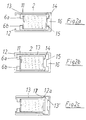
- FIG. 3b and Fig. 4 Another exemplary embodiment of the invention is shown in FIG. 3b and Fig. 4 using largely the same reference numerals shown.
- This is another embodiment with the previously described in design and function largely identical, but shows a difference in terms the captive holder of the locking plug receptacle 2 in that instead of the projections 12 on the Socket 11 of the socket interior near the socket bottom 16 a all around running stage 12a, which acts as a stop for a the locking plug receptacle 2 preferably all around Shoulder 17 serves near the socket bottom. Between the inner wall of the socket and the shoulder 17 runs a gap 13 ', the preferably how gap 13 is dimensioned.
- FIG. 3a The corresponding top view for the embodiments according to FIG. 1 is shown in Fig. 3a, the top view of Fig. 2c in Fig. 3b.
- Fig. 4 shows an exploded view of a socket 11 for the Embodiment according to Fig. 2c, which is not in one piece from a massive workpiece is made, but from a graduated Pipe piece 18 and a separate bottom insert 19 assembled is.
- the surfaces 18a and 19a can be used for assembly by means of gluing, press fitting, spot welding or another known methods are connected.
- Fig. 5 shows an embodiment in which in a double socket 11a two locking plug receptacles 2a, 2b on back Back are arranged.
- the socket bottom instead could have a recess into which a facing Elevation of the locking plug receptacle can intervene. Also could have a partial area on both sides as a recess and be designed as a survey.
- the locking plug receptacle 2 instead of a generally cylindrical outer shape, the locking plug receptacle 2 also generally conical become. If the inside of the socket has the same cone angle provided, arises when the locking plug receptacle is pressed in a desired friction fit into the socket.
Landscapes
- Adornments (AREA)
Description
- Fig.1
- eine Schnittansicht eines erfindungsgemäßen Schmuckstückverschlußes mit einem zugehörigen Stecker;
- Fig. 2a und 2b
- Schnittansichten des Schmuckstückverschlußes von Fig.1, worin die Verschlußsteckeraufnahme unterschiedliche Positionen in der Buchse aufnimmt;
- Fig. 2c
- eine Schnittansicht eines weiteren Schmuckstückverschlußes mit veränderter Sicherung der Verschlußsteckeraufnahme gegen Verlieren;
- Fig. 3a und b
- Draufsichten in die Buchse mit darin angeordneter Verschlußsteckeraufnahme;
- Fig. 4
- eine Explosionsdetailansicht der Buchse des in Fig. 2c gezeigten Ausführungsbeispiels;
- Fig. 5
- eine Schnitt-Ansicht eines weiteren Ausführungsbeispiels.
Claims (14)
- Schmuckstückverschluß (1) mit einer Verschlußsteckeraufnahme (2) zur Aufnahme eines darin in bestimmter Drehwinkelausrichtung axial einschiebbaren und durch Verdrehen gegen Herausziehen bajonettartig sicherbaren Verschlußsteckers (3) mit einer Buchse (11), in welcher die Verschlußsteckeraufnahme (2) unverlierbar gehaltert und axial hin- und herbeweglich zwischen einer ersten Position, in welcher eine relative Drehung zwischen Verschlußsteckeraufnahme und Buchse verhindert ist, und einer weiteren Position aufgenommen ist, dadurch gekennzeichnet, daß die Verschlußsteckeraufnahme in der Buchse in der weiteren Position frei drehbar ist.
- Schmuckstückverschluß nach Anspruch 1, dadurch gekennzeichnet, daß die Verschlußsteckeraufnahme (2) in ihrer axial am weitesten innen in der Buchse (11) liegenden Position am Drehen gehindert ist.
- Schmuckstückverschluß nach Anspruch 2, worin der innere Buchsenboden (16) und das diesem zugewandte Ende der Verschlußsteckeraufnahme ein Erhebung-/Ausnehmungspaar (14, 15) aufweisen, deren Eingriff miteinander die Drehung der Verschlußsteckeraufnahme in der Buchse verhindert.
- Schmuckstückverschluß nach Anspruch 2, worin der innere Buchsenboden und das diesem zugewandte Ende der Verschlußsteckeraufnahme sich in der ersten Position in reibschlüssigem Eingriff miteinander befinden.
- Schmuckstückverschluß nach einem der vorhergehenden Ansprüche, worin die Verschlußsteckeraufnahme (2) außen und die Buchse (11) innen rotationssymmetrisch und vorzugsweise zumindest im wesentlichen zylinderförmig ausgebildet sind.
- Schmuckstückverschluß nach einem der vorhergehenden Ansprüche, worin die Verschlußsteckeraufnahme (2) in der weiteren Position (Pfeil 7a) um wenigstens 360° und vorzugsweise ohne Anschlag um beliebig große Winkel drehbar ist.
- Schmuckstückverschluß nach einem der vorhergehenden Ansprüche, worin ein Spalt (13) zwischen Buchse (11) und Verschlußsteckeraufnahme (2) vorgesehen ist, der klein gegen die axiale und/oder radiale Ausdehnung der Verschlußsteckeraufnahme ist.
- Schmuckstückverschluß nach einem der vorhergehenden Ansprüche, worin der Spalt (13) zwischen Buchse und Verschlußsteckeraufnahme in der weiteren Position so groß ist, daß eine reibungsarme Hin- und Herbewegung der Verschlußsteckeraufnahme in der Buchse möglich ist.
- Schmuckstückverschluß nach einem der vorhergehenden Ansprüche, worin die Verschlußsteckeraufnahme in der Buchse unverlierbar gehalten ist.
- Schmuckstückverschluß nach dem vorhergehenden Anspruch, worin die Verschlußsteckeraufnahme an ihrem vom Stecker abgewandten Ende ringsum eine Schulter mit erhöhtem Außendurchmesser aufweist, die in einem Bereich mit erhöhtem Innendurchmesser in der Aufnahmebuchse unverlierbar gehalten ist.
- Schmuckstückverschluß nach Anspruch 9, dadurch gekennzeichnet, daß die Buchse (11) auf der dem Stecker zugewandten Seite die Verschlußsteckeraufnahme übergreift, um die unverlierbare Halterung zu schaffen.
- Schmuckstückverschluß nach einem der vorhergehenden Ansprüche, worin die Verschlußsteckeraufnahme ein Federelement (9) umfaßt, um den Stecker (3) in der Verschlußstellung elastisch in die verriegelte Position zu fixieren.
- Schmuckstückverschluß nach Anspruch 12, worin die zum Verschieben der Verschlußsteckeraufnahme (2) in die erste Position erforderliche Kraft geringer ist als jene für das Überwinden der Verriegelungs-Fixierung.
- Verfahren zum Verschließen eines Schmuckstückes mit einem Stecker, einer Verschlußsteckeraufhahme und einer Buchse, welche die Verschlußsteckeraufnahme unverlierbar axial beweglich zwischen einer ersten Position, in welcher die Verschlußsteckeraufnahme in der Buchse gegen Verdrehen gesichert ist, und einer weiteren Position hält, in welcher die freie Drehbarkeit der Verschlußsteckeraufnahme gewährleistet ist, worin mit dem Stecker die Verschlußsteckeraufnahme in die erste axiale Position in der Buchse gedrückt wird, der Stecker in die Verschlußsteckeraufnahme gedrückt und bajonettartig mit diesem verrastet wird und nach Entlastung des Steckers ein Zurückgleiten der Verschlußsteckeraufnahme aus der ersten Position erlaubt wird.
Applications Claiming Priority (2)
| Application Number | Priority Date | Filing Date | Title |
|---|---|---|---|
| DE19741406A DE19741406C2 (de) | 1997-09-19 | 1997-09-19 | Schmuckstückverschluß |
| DE19741406 | 1997-09-19 |
Publications (2)
| Publication Number | Publication Date |
|---|---|
| EP0906734A1 EP0906734A1 (de) | 1999-04-07 |
| EP0906734B1 true EP0906734B1 (de) | 2003-03-05 |
Family
ID=7842960
Family Applications (1)
| Application Number | Title | Priority Date | Filing Date |
|---|---|---|---|
| EP98116603A Expired - Lifetime EP0906734B1 (de) | 1997-09-19 | 1998-09-02 | Schmuckstückverschluss |
Country Status (3)
| Country | Link |
|---|---|
| EP (1) | EP0906734B1 (de) |
| AT (1) | ATE233499T1 (de) |
| DE (1) | DE19741406C2 (de) |
Families Citing this family (8)
| Publication number | Priority date | Publication date | Assignee | Title |
|---|---|---|---|---|
| CH695435A5 (de) * | 1999-10-20 | 2006-05-31 | Joerg Heinz Gmbh & Co | Schmuckstückverschluss mit wenigstens einer Bajonettaufnahme sowie Verfahren zu dessen Herstellung. |
| DE19956140B4 (de) * | 1999-10-20 | 2014-12-18 | Jörg Heinz GmbH & Co. KG | Vollkugelschmuckstück |
| DK200500084U3 (da) * | 2005-04-05 | 2005-06-10 | Jepsen Else Birgitte Stengaard | Kædeafslutning med magneter |
| DE102009008409A1 (de) | 2008-12-23 | 2010-12-09 | Jörg Heinz GmbH & Co. KG | Schmuckstück mit schwenkbaren Teilen |
| DE102011015064A1 (de) | 2011-02-25 | 2012-08-30 | Jörg Heinz GmbH & Co. KG | Schmuckstück mit wechselndem Aussehen |
| CN103027448A (zh) * | 2012-10-26 | 2013-04-10 | 设计2有限公司 | 旋转锁扣 |
| CN104490023B (zh) * | 2014-12-18 | 2017-05-03 | 赵威 | 互换式扭钉首饰锁扣 |
| DE102023117340B4 (de) | 2023-06-30 | 2025-07-03 | Jonas Wagner | Verschluss zur wieder lösbaren Verbindung von zwei Elementen |
Family Cites Families (7)
| Publication number | Priority date | Publication date | Assignee | Title |
|---|---|---|---|---|
| DE343348C (de) * | ||||
| GB1035064A (en) * | 1963-06-21 | 1966-07-06 | Marosy Andre | Coupling |
| US4364155A (en) * | 1980-11-03 | 1982-12-21 | Walter Synowicki | Jewelry clasp |
| DE9104214U1 (de) * | 1991-04-08 | 1991-05-29 | Heinzelmann, Dieter, 7534 Birkenfeld | Verschluß für Schmuckketten |
| DE29510652U1 (de) * | 1995-06-30 | 1995-12-21 | Fa. Hanspeter Hösli, Bijouterie-Fournituren, Horgen | Verschlußvorrichtung für Halsschmuck |
| DE29606975U1 (de) * | 1996-04-18 | 1996-09-19 | Heinz, Jörg, 75173 Pforzheim | Verschlußeinrichtung für ein Schmuckstück, insbesondere eine relativ starre Kette |
| DE29610652U1 (de) * | 1996-06-18 | 1997-07-17 | H. Hüttenbrauck Gmbh u. Co. Profil- Walz- und Presswerk, 58730 Fröndenberg | Verstärkungsprofil für Kunststoff-Hohlprofile zur Herstellung von Fenster, Türen o.dgl. |
-
1997
- 1997-09-19 DE DE19741406A patent/DE19741406C2/de not_active Expired - Fee Related
-
1998
- 1998-09-02 EP EP98116603A patent/EP0906734B1/de not_active Expired - Lifetime
- 1998-09-02 AT AT98116603T patent/ATE233499T1/de not_active IP Right Cessation
Also Published As
| Publication number | Publication date |
|---|---|
| ATE233499T1 (de) | 2003-03-15 |
| EP0906734A1 (de) | 1999-04-07 |
| DE19741406A1 (de) | 1999-03-25 |
| DE19741406C2 (de) | 1999-11-04 |
Similar Documents
| Publication | Publication Date | Title |
|---|---|---|
| DE69400724T2 (de) | Uhrengehäuse mit einem abnehmbaren Glasreif | |
| DE102009039156A1 (de) | Schlaufenschloss mit versetzter Zylinderachse | |
| DE2404915C2 (de) | Befestigungsmittel zur lösbaren Befestigung eines Plattenteils an einem Rahmenteil | |
| EP3153648A1 (de) | Hangschloss | |
| DE3020838C2 (de) | ||
| EP0906734B1 (de) | Schmuckstückverschluss | |
| DE3903342A1 (de) | Steckverschluss fuer schmuckteile | |
| DE1932918U (de) | Befestigungsvorrichtung zum schnellen verbinden von plattenfoermigen oder anders gearteten bauteilen. | |
| DE10052288A1 (de) | Schließe für Schmuckstücke | |
| EP2982261B1 (de) | Schmuckanhänger | |
| DE202010016470U1 (de) | Schließknopf und Magnetschlüssel für ein Magnetschloss | |
| DE102007006838B4 (de) | Schließe für Schmuckstück | |
| DE4014829A1 (de) | Zweiteilige schliesse, insbesondere fuer ohrschmuck | |
| DE102010008689A1 (de) | Verschluss für ein Schmuckstück | |
| DE2734482A1 (de) | Brillengestell | |
| DE9003320U1 (de) | Verschluß für Schmuckteile | |
| DE19538314B4 (de) | Schmuckstück, insbesondere Arm- oder Halsreifen | |
| WO1998033411A1 (de) | Schliesse für schmuck | |
| DE2146860A1 (de) | Schloss fuer ein schmuckstueck | |
| EP2463459B1 (de) | Schließknopf und Magnetschlüssel für ein Magnetschloss | |
| DE102009035852B4 (de) | Perlschließe | |
| DE102008023413B4 (de) | Verschlusseinrichtung für ein Schmuckstück | |
| DE2332531A1 (de) | Verschluss | |
| DE8901198U1 (de) | Schließe für Schmuckwaren | |
| AT359391B (de) | Lager fuer drehbare handhaben, wie tuerdruecker, fenstergriffe od.dgl. |
Legal Events
| Date | Code | Title | Description |
|---|---|---|---|
| PUAI | Public reference made under article 153(3) epc to a published international application that has entered the european phase |
Free format text: ORIGINAL CODE: 0009012 |
|
| AK | Designated contracting states |
Kind code of ref document: A1 Designated state(s): AT BE CH CY DE DK ES FI FR GB GR IE IT LI LU MC NL PT SE |
|
| AX | Request for extension of the european patent |
Free format text: AL;LT;LV;MK;RO;SI |
|
| AKX | Designation fees paid | ||
| 17P | Request for examination filed |
Effective date: 19990920 |
|
| RBV | Designated contracting states (corrected) |
Designated state(s): AT CH DK FR GB IT LI |
|
| REG | Reference to a national code |
Ref country code: DE Ref legal event code: 8566 |
|
| GRAH | Despatch of communication of intention to grant a patent |
Free format text: ORIGINAL CODE: EPIDOS IGRA |
|
| GRAH | Despatch of communication of intention to grant a patent |
Free format text: ORIGINAL CODE: EPIDOS IGRA |
|
| GRAA | (expected) grant |
Free format text: ORIGINAL CODE: 0009210 |
|
| AK | Designated contracting states |
Designated state(s): AT CH DK FR GB IT LI |
|
| PG25 | Lapsed in a contracting state [announced via postgrant information from national office to epo] |
Ref country code: GB Free format text: LAPSE BECAUSE OF FAILURE TO SUBMIT A TRANSLATION OF THE DESCRIPTION OR TO PAY THE FEE WITHIN THE PRESCRIBED TIME-LIMIT Effective date: 20030305 Ref country code: FR Free format text: LAPSE BECAUSE OF NON-PAYMENT OF DUE FEES Effective date: 20030305 |
|
| REG | Reference to a national code |
Ref country code: GB Ref legal event code: FG4D Free format text: NOT ENGLISH |
|
| REG | Reference to a national code |
Ref country code: CH Ref legal event code: NV Representative=s name: PA ALDO ROEMPLER Ref country code: CH Ref legal event code: EP |
|
| PG25 | Lapsed in a contracting state [announced via postgrant information from national office to epo] |
Ref country code: DK Free format text: LAPSE BECAUSE OF FAILURE TO SUBMIT A TRANSLATION OF THE DESCRIPTION OR TO PAY THE FEE WITHIN THE PRESCRIBED TIME-LIMIT Effective date: 20030605 |
|
| GBV | Gb: ep patent (uk) treated as always having been void in accordance with gb section 77(7)/1977 [no translation filed] |
Effective date: 20030305 |
|
| PLBE | No opposition filed within time limit |
Free format text: ORIGINAL CODE: 0009261 |
|
| STAA | Information on the status of an ep patent application or granted ep patent |
Free format text: STATUS: NO OPPOSITION FILED WITHIN TIME LIMIT |
|
| EN | Fr: translation not filed | ||
| 26N | No opposition filed |
Effective date: 20031208 |
|
| PGFP | Annual fee paid to national office [announced via postgrant information from national office to epo] |
Ref country code: AT Payment date: 20040929 Year of fee payment: 7 |
|
| PG25 | Lapsed in a contracting state [announced via postgrant information from national office to epo] |
Ref country code: IT Free format text: LAPSE BECAUSE OF NON-PAYMENT OF DUE FEES;WARNING: LAPSES OF ITALIAN PATENTS WITH EFFECTIVE DATE BEFORE 2007 MAY HAVE OCCURRED AT ANY TIME BEFORE 2007. THE CORRECT EFFECTIVE DATE MAY BE DIFFERENT FROM THE ONE RECORDED. Effective date: 20050902 Ref country code: AT Free format text: LAPSE BECAUSE OF NON-PAYMENT OF DUE FEES Effective date: 20050902 |
|
| REG | Reference to a national code |
Ref country code: CH Ref legal event code: PFA Owner name: JOERG HEINZ GMBH & CO. KG Free format text: JOERG HEINZ GMBH & CO.#RINGSTRASSE 4#75173 PFORZHEIM (DE) -TRANSFER TO- JOERG HEINZ GMBH & CO. KG#OBERER STRIETWEG 10#75245 NEULINGEN-GOEBRICHEN (DE) |
|
| REG | Reference to a national code |
Ref country code: CH Ref legal event code: PCAR Free format text: ALDO ROEMPLER PATENTANWALT;BRENDENWEG 11 POSTFACH 154;9424 RHEINECK (CH) |
|
| PGFP | Annual fee paid to national office [announced via postgrant information from national office to epo] |
Ref country code: CH Payment date: 20111217 Year of fee payment: 14 |
|
| REG | Reference to a national code |
Ref country code: CH Ref legal event code: PL |
|
| PG25 | Lapsed in a contracting state [announced via postgrant information from national office to epo] |
Ref country code: LI Free format text: LAPSE BECAUSE OF NON-PAYMENT OF DUE FEES Effective date: 20120930 Ref country code: CH Free format text: LAPSE BECAUSE OF NON-PAYMENT OF DUE FEES Effective date: 20120930 |