EP0904898B1 - Durchgesteckte Greifzange mit verstellbarer Maulweite - Google Patents
Durchgesteckte Greifzange mit verstellbarer Maulweite Download PDFInfo
- Publication number
- EP0904898B1 EP0904898B1 EP98113066A EP98113066A EP0904898B1 EP 0904898 B1 EP0904898 B1 EP 0904898B1 EP 98113066 A EP98113066 A EP 98113066A EP 98113066 A EP98113066 A EP 98113066A EP 0904898 B1 EP0904898 B1 EP 0904898B1
- Authority
- EP
- European Patent Office
- Prior art keywords
- area
- pliers
- gripping
- diameter
- joint
- Prior art date
- Legal status (The legal status is an assumption and is not a legal conclusion. Google has not performed a legal analysis and makes no representation as to the accuracy of the status listed.)
- Expired - Lifetime
Links
Images

Classifications
-
- B—PERFORMING OPERATIONS; TRANSPORTING
- B25—HAND TOOLS; PORTABLE POWER-DRIVEN TOOLS; MANIPULATORS
- B25B—TOOLS OR BENCH DEVICES NOT OTHERWISE PROVIDED FOR, FOR FASTENING, CONNECTING, DISENGAGING, OR HOLDING
- B25B7/00—Pliers; Other hand-held gripping tools with jaws on pivoted limbs; Details applicable generally to pivoted-limb hand tools
- B25B7/06—Joints
- B25B7/10—Joints with adjustable fulcrum
Definitions
- the present invention relates to a gripper with the Features of the preamble of claim 1 which DE 296 20 588 U is known.
- gripping pliers are from practice and in particular from the publications DE-PS 805 265 and DE-92 18 069 U1 known.
- the cross Forceps handle and the forceps bracket in one joint, the one elongated locking hole includes.
- the forceps handle forms the lower jaw as well as the upper one Handle lever, while the pliers bracket is the upper one in use Pliers jaw and the lower handle lever forms.
- a pin that forms the bearing axis of the joint is in the Cross-section shaped like a star or round and engages in Longitudinal direction of the slot in the im Pliers bracket a locking hole.
- the spigot is in its latched position from an unprotected one Leaf spring biased, which is on the the journal opposite the outside of the joint.
- To the Adjusting the mouth width of the known gripping pliers is the Pin against the force of the leaf spring in the pliers joint indent so that its larger cross section from the The locking hole is pushed out. Then the clamp can be adjusted against the pliers handle to the desired extent. As soon as the pin is released, the leaf spring presses him in the engaged position with the locking hole, and the The intended jaw width of the gripper is fixed.
- the slotted handle and the Pliers bracket in the joint area through the pliers handle through put is the slotted handle and the Pliers bracket in the joint area through the pliers handle through put.
- the aim is the clamp in the joint area to about half of the Total thickness to be dimensioned so that the load-bearing surfaces of the am Locking pins on the joint parts on the clamp and Pliers handle are about the same size Gripping pliers it is therefore necessary to solve the Snap connection the locking pin by about half Pliers thickness corresponding amount across the longitudinal plane of the pliers to relocate. It is perceived as a disadvantage that this path is relatively long and the free actuation end the locking bolt laterally significantly in the rest position the joint protrudes.
- DE 296 20 588 U shows a gripper similar to that documents mentioned above.
- the pliers bracket slotted and the Pliers handle can be inserted. Training the The joint is not described.
- This task is carried out by a gripper with the characteristics of claim 1 solved.
- An easy-to-manufacture adjustment element results if this one is essentially rotationally symmetrical Includes locking pin.
- the locking pin can be in its Position of engagement at the same time the bearing axis of the joint form. Good storage continues if the Locking pin a first area of smaller diameter, a second area of medium diameter and one has third area of larger diameter.
- a particularly robust embodiment that also works against Damage and pollution is insensitive looks before that the one locking hole of the pliers bracket a number of itself overlapping, small locking holes of a first Has bore diameter and the other Locking hole a number of overlapping large locking holes a second larger bore diameter, wherein also a hole of the first diameter and one Bore of second diameter arranged coaxially to one another are.
- This embodiment is further improved by that the locking pin in the engaged position with his second area of medium diameter in a bore of the engages the first locking hole and with its third area large diameter in a hole in the second locking hole engages so that the locking pin in the pliers plane is positively fixed, and the locking pin in the Adjustment position in its first area small Diameter longitudinally displaceable in the first locking hole engages and middle with its second area Diameter longitudinally displaceable in the second locking hole engages so that the locking pin in the plane of the pliers Overall length of the locking holes is displaceable.
- a helical spring is advantageously provided as the spring, which engages in an axially parallel bore of the locking pin.
- the forceps handle acts as an abutment in the area of the joint a pin arranged transversely to the locking pin against which the spring is supported and which penetrates the locking pin. With this pin the locking pin is captively secured.
- Figure 1 shows a gripping pliers according to the invention a slotted tongs 1 and a push-through Forceps handle 2.
- the forceps bracket 1 carries in his slotted joint area 3 an elongated locking hole 4, the in this embodiment of a total of 7 rounds Bores 5 is formed.
- the holes 5 are in one straight line next to each other and overlap partially.
- the clamp 1 carries an upper one Pliers jaw 6 and a lower one in use Handle section 7.
- the pliers handle 2 carries a lower jaw 8 and an upper one in use Handle section 9.
- a locking pin 11 is provided, both penetrates the clamp 1 and the handle 2 and the one in the locked position in the locking hole 4th immovable bearing axis for the clamp 1 and Pliers handle 2 forms.
- FIG. 2 shows the locking pin 11 in a side view.
- the locking pin 11 has one essentially rotationally symmetrical base body 12. This carries a first area 13 of smaller diameter, one the area 14 adjoining the second area 14 middle Diameter and one adjoining the area 14 third area 15 of large diameter.
- the areas 13 and 14 and 14 and 15 are each via a chamfer 16 attached to each other.
- Sitting inside the locking pin 11 in the middle an axial blind bore 17, which the area 13 and the area 14 completely penetrated.
- One with the Base body 12 screwed or glued cap 18th closes the blind hole at its open end.
- a coil spring 19 is used in the Blind bore 17 .
- the base body 12 of the locking pin 11 is transverse, d. H. in the radial direction, from an elongated hole 20 interspersed.
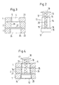
- FIG 3 the joint area of the gripping pliers according to Figure 1 approximately in a cross section along the line III-III shown in Figure 1.
- the clamp 1 points in this area an upper cheek 21 and a lower cheek 22 on.
- the upper cheek 21 carries the locking hole 4 with its overlapping holes 5, while the lower cheek 22 a corresponding locking hole 24 and overlapping bores 25 having.
- the pliers handle 2 runs in this Joint area between the two cheeks 21 and 22 of the Pliers bracket 1.
- the pliers handle 2 also has a round Through hole 26 on a radially transverse at one end is assigned via the bore 26 extending pin 27.
- the locking hole 4 is so with its overlapping holes 5 designed that the diameter of each hole 5 the Inner diameter of the bore 26 of the gripper arm 2 corresponds to, while in the overlap area two Adjacent holes 5 the clear cross section of the Rest hole 2 is narrowed.
- This design of a rest hole is generally known from adjustable water pump pliers.
- the locking hole 24 of the lower cheek 22 is in the clear width made larger. Here corresponds to Area of overlap between two bores 25 in its clear width of the bore diameter of the holes 5 and 26, while the actual bore diameter of the Bores 25 is larger than this.
- FIG. 4 finally shows the locking pin according to FIG. 2 (rotated 90 ° around its axis) according to the joint area Figure 3 used. Identify the same reference numbers components already described here.
- the locking pin 12 In the engagement position shown is the locking pin 12 its area 13 of smaller diameter outside the Forceps joint, while the area 14 middle Diameter a locking hole 5 and the bore 26 of the Pliers handle 2 interspersed.
- the pin 27 passes through the slot 20 of the locking pin 11, so that the coil spring 19 with one end against the pin 27 and can support against the head 18 with the other end. On in this way, the coil spring 19 tensions the locking pin 11 in the joint in this snap position.
- a shift of the locking pin in the axial direction simple amount of the thickness of a cheek 21 or 22 sufficient to completely unlock the pliers joint. If the pliers joint is dimensioned so that the same Each cheek can bear the same load on surfaces 21 and 22 are kept narrower in width than that Joint area of the forceps handle. For example, from the Total thickness of the joint each cheek 21 and 22 a quarter make up while the thickness of the forceps in this Area makes up half. With this configuration is so it is possible to increase the height of the area 13 by a quarter the total thickness of the joint in this area, so that the axial displacement for unlocking must be only a quarter of the thickness. Both known grippers with adjustable, lockable Maul is the required actuation path of the locking element each twice as large.
Landscapes
- Engineering & Computer Science (AREA)
- Mechanical Engineering (AREA)
- Gripping Jigs, Holding Jigs, And Positioning Jigs (AREA)
- Hand Tools For Fitting Together And Separating, Or Other Hand Tools (AREA)
- Portable Nailing Machines And Staplers (AREA)
Description
- Fig. 1:
- Eine erfindungsgemäße Greifzange mit geschlitztem Bügel und durchgestecktem Stiel in einer Seitenansicht auf die Betätigungsseite des Raststifts;
- Fig. 2
- den Raststift in einem Querschnitt von der Seite;
- Fig. 3
- einen Querschnitt durch den Gelenkbereich der erfindungsgemäßen Greifzange in einer abgebrochenen Darstellung, sowie
- Fig. 4:
- den Raststift gemäß Figur 2, eingesetzt in den Gelenkbereich gemäß Figur 3 in seiner Eingriffsstellung.
Claims (8)
- Greifzange mit einem Zangenstiel (2) und einem Zangenbügel (1), die jeweils einen Griffabschnitt (9,7) und eine dem Griffabschnitt (9,7) gegenüberliegende Backe (8,6) aufweisen, wobei der Zangenstiel (2) und der Zangenbügel (1) in einem durchgesteckten Gelenk zueinander um eine Schwenkachse schwenkbar gelagert sind und das Gelenk eine Eingriffsposition und eine Verstellposition aufweist, wobei weiterhin ein in Richtung der Schwenkachse gegen eine Feder (19) manuell verlagerbarer, das Gelenk bildender Raststift (11) zur Einstellung der Eingriffsposition und der Verstellposition vorgesehen ist, und wobei der Zangenbügel (1) im Gelenkbereich geschlitzt ist und der Zangenstiel (2) im Gelenkbereich durch den Zangenbügel (1) hindurchgesteckt ist
dadurch gekennzeichnet, dass der Zangenbügel (1) im Gelenkbereich zwei längliche, sich quer zu der Zangenebene gegenüberliegende Rastlöcher (4,24) aufweist. - Greifzange nach Anspruch 1, dadurch gekennzeichnet, daß der Raststift (11) im wesentlichen rotationssymmetrisch ist.
- Greifzange nach einem der vorherigen Ansprüche, dadurch gekennzeichnet, daß der Raststift (11) einen ersten Bereich (13) kleineren Durchmessers, einen zweiten Bereich (14) mittleren Durchmessers und einen dritten Bereich (15) größeren Durchmessers aufweist.
- Greifzange nach einem der vorherigen Ansprüche, dadurch gekennzeichnet, daß das eine Rastloch (4) eine Anzahl von überlappenden kleinen Rastbohrungen (5) eines ersten Bohrungsdurchmessers aufweist und das andere Rastloch (24) eine Anzahl von überlappenden großen Rastbohrungen (25) eines zweiten größeren Bohrungsdurchmessers aufweist, wobei außerdem jeweils eine Bohrung (5) ersten Durchmessers und eine Bohrung (25) zweiten Durchmessers koaxial zueinander angeordnet sind.
- Greifzange nach einem der vorherigen Ansprüche, dadurch gekennzeichnet, daß der Raststift (11) in der Eingriffsposition mit seinem zweiten Bereich (14) mittleren Durchmessers in eine Bohrung (5) des ersten Rastlochs eingreift und mit seinem dritten Bereich (15) großen Durchmessers in eine Bohrung (25) des zweiten Rastlochs (24) eingreift, so daß der Raststift (11) in der Zangenebene formschlüssig fixiert ist, und daß der Raststift (11) in der Verstellposition mit seinem ersten Bereich (13) kleinen Durchmessers längsverschieblich in das erste Rastloch (4) eingreift und mit seinem zweiten Bereich (14) mittleren Durchmessers längsverschieblich in das zweite Rastloch (24) eingreift, so daß der Raststift (11) in der Zangenebene in Längsrichtung der Rastlöcher (24) verschieblich ist.
- Greifzange nach einem der vorherigen Ansprüche, dadurch gekennzeichnet, daß als Feder (19) eine Schraubenfeder vorgesehen ist, die in eine achsparallele Bohrung (17) des Raststiftes (11) eingreift.
- Greifzange nach einem der vorherigen Ansprüche, dadurch gekennzeichnet, daß der Zangenstiel (2) im Bereich des Gelenks einen quer zu dem Raststift (11) angeordneten Stift (27) trägt, gegen den die Feder (19) abgestützt ist und der den Raststift (11) durchsetzt.
- Greifzange nach einem der vorherigen Ansprüche, dadurch gekennzeichnet, daß der Raststift (11) an seiner dem ersten Bereich (13) benachbarten Stirnseite einen Verschluß (18) aufweist, der die Bohrung (17) nach außen verschließt.
Applications Claiming Priority (3)
| Application Number | Priority Date | Filing Date | Title |
|---|---|---|---|
| DE19741796A DE19741796A1 (de) | 1997-09-22 | 1997-09-22 | Durchgesteckte Greifzange mit verstellbarer Maulweite |
| DE19741796 | 1997-09-22 | ||
| US09/392,962 US6318217B1 (en) | 1997-09-22 | 1999-09-09 | Through-bolt gripping pliers with adjustable opening width |
Publications (3)
| Publication Number | Publication Date |
|---|---|
| EP0904898A2 EP0904898A2 (de) | 1999-03-31 |
| EP0904898A3 EP0904898A3 (de) | 2000-04-26 |
| EP0904898B1 true EP0904898B1 (de) | 2003-04-09 |
Family
ID=26040203
Family Applications (1)
| Application Number | Title | Priority Date | Filing Date |
|---|---|---|---|
| EP98113066A Expired - Lifetime EP0904898B1 (de) | 1997-09-22 | 1998-07-14 | Durchgesteckte Greifzange mit verstellbarer Maulweite |
Country Status (5)
| Country | Link |
|---|---|
| US (1) | US6318217B1 (de) |
| EP (1) | EP0904898B1 (de) |
| AT (1) | ATE236763T1 (de) |
| DE (2) | DE19741796A1 (de) |
| ES (1) | ES2255118T3 (de) |
Families Citing this family (26)
| Publication number | Priority date | Publication date | Assignee | Title |
|---|---|---|---|---|
| FR2786119B1 (fr) * | 1998-11-19 | 2001-02-09 | Bost Garnache Ind | Pince a au moins deux positions de reglage |
| USRE45680E1 (en) * | 2000-07-19 | 2015-09-29 | Stanley Works (Europe) Gmbh | Transversely retained multiple slip-joint pliers |
| FR2811925B1 (fr) * | 2000-07-19 | 2003-01-24 | Facom | Pince multiprise entrepassee |
| US20040194317A1 (en) * | 2003-01-27 | 2004-10-07 | Pippert Aaron J. | Adjustable nut cracker |
| GB2400065B (en) * | 2003-04-02 | 2006-04-12 | Irwin Ind Tool Co | Quick adjusting pliers |
| US7100480B2 (en) * | 2003-04-02 | 2006-09-05 | Irwin Industrial Tool Company | Quick adjusting pliers |
| DE202004012362U1 (de) * | 2004-08-06 | 2004-10-14 | Eduard Wille Gmbh & Co. Kg | Greifzange |
| USD543812S1 (en) | 2004-11-05 | 2007-06-05 | Irwin Industrial Tool Company | Groovelock tool |
| ES2277520B1 (es) * | 2005-06-01 | 2008-05-16 | Rothenberger, S.A. | Tenaza. |
| US7174816B1 (en) * | 2005-07-26 | 2007-02-13 | Helen Of Troy Limited | Visual alignment features for adjusting tongue and groove pliers |
| USD589315S1 (en) * | 2007-05-30 | 2009-03-31 | Knipex-Werk C. Gustav Putsch Kg | Pliers |
| USD588890S1 (en) * | 2007-11-27 | 2009-03-24 | Rothenberger, S.A. | Pliers |
| US7681477B2 (en) * | 2008-01-31 | 2010-03-23 | The Stanley Works | Adjustable pliers |
| US20100018362A1 (en) * | 2008-07-28 | 2010-01-28 | Irwin Industrial Tool Company | Locking pliers |
| US20100018364A1 (en) * | 2008-07-28 | 2010-01-28 | Irwin Industrial Tool Company | Quick adjusting multi-position pliers |
| US7861622B2 (en) * | 2008-07-28 | 2011-01-04 | Irwin Industrial Tool Company | Locking pliers |
| USD635428S1 (en) | 2009-08-21 | 2011-04-05 | Irwin Industrial Tool Company | Locking pliers jaw |
| USD635427S1 (en) | 2009-08-21 | 2011-04-05 | Irwin Industrial Tool Company | Locking pliers jaw |
| USD782891S1 (en) | 2015-04-02 | 2017-04-04 | Milwaukee Electric Tool Corporation | Locking pliers |
| CN104874656B (zh) * | 2015-05-29 | 2017-01-25 | 清华大学 | 一种自适应快速管夹 |
| GB2540621A (en) * | 2015-07-24 | 2017-01-25 | Stanley Works (Europe) Ag | Adjustable pliers |
| US11911879B1 (en) * | 2016-09-06 | 2024-02-27 | Ector Cantu Gomez | Chrome flush valve installation tool |
| CN108581906A (zh) * | 2018-05-11 | 2018-09-28 | 杭州临安制钳有限公司 | 一种可调节扳手 |
| TWI680037B (zh) * | 2018-12-28 | 2019-12-21 | 游再順 | 易解鎖扣的管鉗 |
| TWI727803B (zh) * | 2020-05-20 | 2021-05-11 | 王衍裕 | 工具夾口寬度調整結構 |
| US11691249B2 (en) | 2020-07-29 | 2023-07-04 | Snap-On Incorporated | Push button release mechanism for pliers |
Family Cites Families (14)
| Publication number | Priority date | Publication date | Assignee | Title |
|---|---|---|---|---|
| DE1600360U (de) * | 1948-10-29 | 1950-02-02 | Ver Beckersche Werkzeugfab | Wasserpumpenzange. |
| DE805265C (de) * | 1948-11-04 | 1951-05-10 | Walter Gott Gesenkschmiede Und | Zange |
| FR2052020A5 (de) * | 1969-07-11 | 1971-04-09 | Stephanoises Forges | |
| US4269089A (en) * | 1978-11-24 | 1981-05-26 | Hastings Charles E | Adjustable ratchet pliers |
| US4232573A (en) * | 1979-01-08 | 1980-11-11 | Dace Jr Marvin H | Slip pliers with lock |
| US4296655A (en) * | 1980-05-12 | 1981-10-27 | Joseph Tesoro | Slip joint pliers |
| DE3460942D1 (en) * | 1983-02-02 | 1986-11-20 | Putsch Gustav Knipex Werk | Gripping plyers |
| GB8506017D0 (en) * | 1985-03-08 | 1985-04-11 | Stafford M A | Adjustable wrench |
| JPH0435096Y2 (de) * | 1985-11-02 | 1992-08-20 | ||
| US4773288A (en) * | 1987-06-08 | 1988-09-27 | Jang Young H | Adjustable vise grip |
| DE9218069U1 (de) * | 1991-08-08 | 1993-07-29 | Knipex-Werk C. Gustav Putsch, 5600 Wuppertal | Zange mit zwei Zangenschenkeln |
| DE9109863U1 (de) * | 1991-08-09 | 1991-10-17 | U.S.H.-Fittings + Kunststoffteile GmbH, 4815 Schloß Holte-Stukenbrock | Wasserpumpenzange |
| SE9402978L (sv) * | 1994-09-07 | 1995-12-04 | Kent Lundell | Sätt och anordning för demontering av lister, företrädesvis fönsterlister snäppbara på en karm, samt metod för tillverkning av anordningen |
| DE19634082A1 (de) * | 1996-08-23 | 1998-02-26 | Ver Beckersche Werkzeugfab | Greifzange mit verstellbarer Maulweite |
-
1997
- 1997-09-22 DE DE19741796A patent/DE19741796A1/de not_active Withdrawn
-
1998
- 1998-07-14 AT AT98113066T patent/ATE236763T1/de not_active IP Right Cessation
- 1998-07-14 DE DE59807825T patent/DE59807825D1/de not_active Expired - Fee Related
- 1998-07-14 EP EP98113066A patent/EP0904898B1/de not_active Expired - Lifetime
- 1998-07-14 ES ES98113066T patent/ES2255118T3/es not_active Expired - Lifetime
-
1999
- 1999-09-09 US US09/392,962 patent/US6318217B1/en not_active Expired - Fee Related
Also Published As
| Publication number | Publication date |
|---|---|
| ES2255118T3 (es) | 2006-06-16 |
| US6318217B1 (en) | 2001-11-20 |
| EP0904898A3 (de) | 2000-04-26 |
| EP0904898A2 (de) | 1999-03-31 |
| ATE236763T1 (de) | 2003-04-15 |
| DE19741796A1 (de) | 1999-03-25 |
| DE59807825D1 (de) | 2003-05-15 |
Similar Documents
| Publication | Publication Date | Title |
|---|---|---|
| EP0904898B1 (de) | Durchgesteckte Greifzange mit verstellbarer Maulweite | |
| DE3804354C2 (de) | ||
| DE10138079A1 (de) | Platzhalter mit veränderbarer axialer Länge | |
| EP1623796B1 (de) | Greifzange | |
| EP1394012B1 (de) | Verriegelungsvorrichtung für zwei relativ zueinander verschiebbar gelagerte Bauteile | |
| DE2916242C2 (de) | Sicherheitsanordnung für Türen, Fenster o.dgl. | |
| DE3023882C2 (de) | ||
| DE3813342A1 (de) | Klemmeinrichtung | |
| DE60038654T2 (de) | Klemmhalterung für Stütz- und Verbindungselemente | |
| EP0309880B1 (de) | Handwerkzeug | |
| DE2931873A1 (de) | Gelenkbeschlag mit verstellbarer rueckenlehne, insbesondere fuer kraftfahrzeugsitze | |
| EP0824996A1 (de) | Greifzange mit verstellbarer Maulweite | |
| DE29505752U1 (de) | Vorrichtung zum Verbinden von Platten mittels Verschraubung | |
| DE3632026C2 (de) | ||
| DE4412056C2 (de) | Kabelschloß | |
| DE69205974T2 (de) | Vorrichtung zum abwechselnden steuern von zwei zusammenwirkenden ventilen, insbesondere von sicherheitsventilen an druckkesseln. | |
| DE3005692A1 (de) | Gelenkbeschlag fuer klappbare leitern | |
| DE19904713C1 (de) | Vorrichtung zur axialen Festlegung eines Bolzens | |
| DE2321346C3 (de) | Gelenkbeschlag für klappbare Leitern | |
| DE4211796C2 (de) | Vorrichtung zum Verbinden und Verriegeln zweier Elemente | |
| DE1258758B (de) | Loesbare, auf beliebige Tuerdicke einstellbare Tuerdrueckerklemmbefestigung | |
| DE29518029U1 (de) | Handschere | |
| DE10314291A1 (de) | Anschlagmittel mit Sicherungseinrichtung für eine Kette | |
| DE10301687B3 (de) | Halter für chirurgische Eingriffe im Kieferbereich | |
| WO2002008616A1 (de) | Schraube |
Legal Events
| Date | Code | Title | Description |
|---|---|---|---|
| PUAI | Public reference made under article 153(3) epc to a published international application that has entered the european phase |
Free format text: ORIGINAL CODE: 0009012 |
|
| AK | Designated contracting states |
Kind code of ref document: A2 Designated state(s): AT BE CH DE DK FR GB IT LI NL |
|
| AX | Request for extension of the european patent |
Free format text: AL;LT;LV;MK;RO;SI |
|
| PUAL | Search report despatched |
Free format text: ORIGINAL CODE: 0009013 |
|
| AK | Designated contracting states |
Kind code of ref document: A3 Designated state(s): AT BE CH CY DE DK ES FI FR GB GR IE IT LI LU MC NL PT SE |
|
| AX | Request for extension of the european patent |
Free format text: AL;LT;LV;MK;RO;SI |
|
| 17P | Request for examination filed |
Effective date: 20000628 |
|
| 111L | Licence recorded |
Free format text: 20000512 0100 FACOM * 20000725 0101 BOST GARNACHE INDUSTRIES (GBI) |
|
| AKX | Designation fees paid |
Free format text: AT BE CH DE DK FR GB IT LI NL |
|
| 17Q | First examination report despatched |
Effective date: 20011203 |
|
| GRAH | Despatch of communication of intention to grant a patent |
Free format text: ORIGINAL CODE: EPIDOS IGRA |
|
| GRAH | Despatch of communication of intention to grant a patent |
Free format text: ORIGINAL CODE: EPIDOS IGRA |
|
| GRAA | (expected) grant |
Free format text: ORIGINAL CODE: 0009210 |
|
| AK | Designated contracting states |
Designated state(s): AT BE CH DE DK FR GB IT LI NL |
|
| PG25 | Lapsed in a contracting state [announced via postgrant information from national office to epo] |
Ref country code: SE Free format text: LAPSE BECAUSE OF FAILURE TO SUBMIT A TRANSLATION OF THE DESCRIPTION OR TO PAY THE FEE WITHIN THE PRESCRIBED TIME-LIMIT Effective date: 20030409 Ref country code: LU Free format text: LAPSE BECAUSE OF FAILURE TO SUBMIT A TRANSLATION OF THE DESCRIPTION OR TO PAY THE FEE WITHIN THE PRESCRIBED TIME-LIMIT Effective date: 20030409 Ref country code: IE Free format text: LAPSE BECAUSE OF FAILURE TO SUBMIT A TRANSLATION OF THE DESCRIPTION OR TO PAY THE FEE WITHIN THE PRESCRIBED TIME-LIMIT Effective date: 20030409 Ref country code: CY Free format text: LAPSE BECAUSE OF FAILURE TO SUBMIT A TRANSLATION OF THE DESCRIPTION OR TO PAY THE FEE WITHIN THE PRESCRIBED TIME-LIMIT Effective date: 20030409 |
|
| REG | Reference to a national code |
Ref country code: GB Ref legal event code: FG4D Free format text: NOT ENGLISH |
|
| REG | Reference to a national code |
Ref country code: CH Ref legal event code: EP |
|
| PG25 | Lapsed in a contracting state [announced via postgrant information from national office to epo] |
Ref country code: DK Free format text: LAPSE BECAUSE OF FAILURE TO SUBMIT A TRANSLATION OF THE DESCRIPTION OR TO PAY THE FEE WITHIN THE PRESCRIBED TIME-LIMIT Effective date: 20030709 |
|
| PG25 | Lapsed in a contracting state [announced via postgrant information from national office to epo] |
Ref country code: AT Free format text: LAPSE BECAUSE OF NON-PAYMENT OF DUE FEES Effective date: 20030714 |
|
| PG25 | Lapsed in a contracting state [announced via postgrant information from national office to epo] |
Ref country code: FI Free format text: LAPSE BECAUSE OF NON-PAYMENT OF DUE FEES Effective date: 20030731 Ref country code: BE Free format text: LAPSE BECAUSE OF NON-PAYMENT OF DUE FEES Effective date: 20030731 |
|
| GBT | Gb: translation of ep patent filed (gb section 77(6)(a)/1977) |
Effective date: 20030724 |
|
| PG25 | Lapsed in a contracting state [announced via postgrant information from national office to epo] |
Ref country code: MC Free format text: LAPSE BECAUSE OF NON-PAYMENT OF DUE FEES Effective date: 20031231 |
|
| ET | Fr: translation filed | ||
| BERE | Be: lapsed |
Owner name: VEREINIGTE BECKERSCHE WERKZEUGFABRIKEN G.M.B.H. & Effective date: 20030731 |
|
| PLBE | No opposition filed within time limit |
Free format text: ORIGINAL CODE: 0009261 |
|
| STAA | Information on the status of an ep patent application or granted ep patent |
Free format text: STATUS: NO OPPOSITION FILED WITHIN TIME LIMIT |
|
| 26N | No opposition filed |
Effective date: 20040112 |
|
| RBV | Designated contracting states (corrected) |
Designated state(s): AT BE CH CY DE DK ES FI FR GB GR IE IT LI LU MC NL PT SE |
|
| REG | Reference to a national code |
Ref country code: IE Ref legal event code: FG4D Free format text: GERMAN Ref country code: IE Ref legal event code: FD4D |
|
| REG | Reference to a national code |
Ref country code: ES Ref legal event code: FG2A Ref document number: 2255118 Country of ref document: ES Kind code of ref document: T3 |
|
| REG | Reference to a national code |
Ref country code: ES Ref legal event code: FD2A Effective date: 20030715 |
|
| PG25 | Lapsed in a contracting state [announced via postgrant information from national office to epo] |
Ref country code: PT Free format text: LAPSE BECAUSE OF NON-PAYMENT OF DUE FEES Effective date: 20030909 |
|
| PG25 | Lapsed in a contracting state [announced via postgrant information from national office to epo] |
Ref country code: GR Free format text: LAPSE BECAUSE OF NON-PAYMENT OF DUE FEES Effective date: 20030409 |
|
| PGFP | Annual fee paid to national office [announced via postgrant information from national office to epo] |
Ref country code: FR Payment date: 20090720 Year of fee payment: 12 Ref country code: ES Payment date: 20090724 Year of fee payment: 12 |
|
| PGFP | Annual fee paid to national office [announced via postgrant information from national office to epo] |
Ref country code: NL Payment date: 20090724 Year of fee payment: 12 Ref country code: GB Payment date: 20090724 Year of fee payment: 12 Ref country code: DE Payment date: 20090702 Year of fee payment: 12 Ref country code: CH Payment date: 20090727 Year of fee payment: 12 |
|
| PGFP | Annual fee paid to national office [announced via postgrant information from national office to epo] |
Ref country code: IT Payment date: 20090727 Year of fee payment: 12 |
|
| REG | Reference to a national code |
Ref country code: NL Ref legal event code: V1 Effective date: 20110201 |
|
| REG | Reference to a national code |
Ref country code: CH Ref legal event code: PL |
|
| GBPC | Gb: european patent ceased through non-payment of renewal fee |
Effective date: 20100714 |
|
| REG | Reference to a national code |
Ref country code: FR Ref legal event code: ST Effective date: 20110331 |
|
| PG25 | Lapsed in a contracting state [announced via postgrant information from national office to epo] |
Ref country code: CH Free format text: LAPSE BECAUSE OF NON-PAYMENT OF DUE FEES Effective date: 20100731 Ref country code: DE Free format text: LAPSE BECAUSE OF NON-PAYMENT OF DUE FEES Effective date: 20110201 Ref country code: LI Free format text: LAPSE BECAUSE OF NON-PAYMENT OF DUE FEES Effective date: 20100731 |
|
| REG | Reference to a national code |
Ref country code: DE Ref legal event code: R119 Ref document number: 59807825 Country of ref document: DE Effective date: 20110201 |
|
| PG25 | Lapsed in a contracting state [announced via postgrant information from national office to epo] |
Ref country code: NL Free format text: LAPSE BECAUSE OF NON-PAYMENT OF DUE FEES Effective date: 20110201 Ref country code: FR Free format text: LAPSE BECAUSE OF NON-PAYMENT OF DUE FEES Effective date: 20100802 Ref country code: IT Free format text: LAPSE BECAUSE OF NON-PAYMENT OF DUE FEES Effective date: 20100714 |
|
| PG25 | Lapsed in a contracting state [announced via postgrant information from national office to epo] |
Ref country code: GB Free format text: LAPSE BECAUSE OF NON-PAYMENT OF DUE FEES Effective date: 20100714 |
|
| REG | Reference to a national code |
Ref country code: ES Ref legal event code: FD2A Effective date: 20110818 |
|
| PG25 | Lapsed in a contracting state [announced via postgrant information from national office to epo] |
Ref country code: ES Free format text: LAPSE BECAUSE OF NON-PAYMENT OF DUE FEES Effective date: 20100715 |