EP0904898B1 - Wrench with variable opening and interlocking arms - Google Patents
Wrench with variable opening and interlocking arms Download PDFInfo
- Publication number
- EP0904898B1 EP0904898B1 EP98113066A EP98113066A EP0904898B1 EP 0904898 B1 EP0904898 B1 EP 0904898B1 EP 98113066 A EP98113066 A EP 98113066A EP 98113066 A EP98113066 A EP 98113066A EP 0904898 B1 EP0904898 B1 EP 0904898B1
- Authority
- EP
- European Patent Office
- Prior art keywords
- area
- pliers
- gripping
- diameter
- joint
- Prior art date
- Legal status (The legal status is an assumption and is not a legal conclusion. Google has not performed a legal analysis and makes no representation as to the accuracy of the status listed.)
- Expired - Lifetime
Links
- 238000006073 displacement reaction Methods 0.000 description 1
- 230000000694 effects Effects 0.000 description 1
- 238000003780 insertion Methods 0.000 description 1
- 230000037431 insertion Effects 0.000 description 1
- 238000004519 manufacturing process Methods 0.000 description 1
- XLYOFNOQVPJJNP-UHFFFAOYSA-N water Substances O XLYOFNOQVPJJNP-UHFFFAOYSA-N 0.000 description 1
Images

Classifications
-
- B—PERFORMING OPERATIONS; TRANSPORTING
- B25—HAND TOOLS; PORTABLE POWER-DRIVEN TOOLS; MANIPULATORS
- B25B—TOOLS OR BENCH DEVICES NOT OTHERWISE PROVIDED FOR, FOR FASTENING, CONNECTING, DISENGAGING OR HOLDING
- B25B7/00—Pliers; Other hand-held gripping tools with jaws on pivoted limbs; Details applicable generally to pivoted-limb hand tools
- B25B7/06—Joints
- B25B7/10—Joints with adjustable fulcrum
Definitions
- the present invention relates to a gripper with the Features of the preamble of claim 1 which DE 296 20 588 U is known.
- gripping pliers are from practice and in particular from the publications DE-PS 805 265 and DE-92 18 069 U1 known.
- the cross Forceps handle and the forceps bracket in one joint, the one elongated locking hole includes.
- the forceps handle forms the lower jaw as well as the upper one Handle lever, while the pliers bracket is the upper one in use Pliers jaw and the lower handle lever forms.
- a pin that forms the bearing axis of the joint is in the Cross-section shaped like a star or round and engages in Longitudinal direction of the slot in the im Pliers bracket a locking hole.
- the spigot is in its latched position from an unprotected one Leaf spring biased, which is on the the journal opposite the outside of the joint.
- To the Adjusting the mouth width of the known gripping pliers is the Pin against the force of the leaf spring in the pliers joint indent so that its larger cross section from the The locking hole is pushed out. Then the clamp can be adjusted against the pliers handle to the desired extent. As soon as the pin is released, the leaf spring presses him in the engaged position with the locking hole, and the The intended jaw width of the gripper is fixed.
- the slotted handle and the Pliers bracket in the joint area through the pliers handle through put is the slotted handle and the Pliers bracket in the joint area through the pliers handle through put.
- the aim is the clamp in the joint area to about half of the Total thickness to be dimensioned so that the load-bearing surfaces of the am Locking pins on the joint parts on the clamp and Pliers handle are about the same size Gripping pliers it is therefore necessary to solve the Snap connection the locking pin by about half Pliers thickness corresponding amount across the longitudinal plane of the pliers to relocate. It is perceived as a disadvantage that this path is relatively long and the free actuation end the locking bolt laterally significantly in the rest position the joint protrudes.
- DE 296 20 588 U shows a gripper similar to that documents mentioned above.
- the pliers bracket slotted and the Pliers handle can be inserted. Training the The joint is not described.
- This task is carried out by a gripper with the characteristics of claim 1 solved.
- An easy-to-manufacture adjustment element results if this one is essentially rotationally symmetrical Includes locking pin.
- the locking pin can be in its Position of engagement at the same time the bearing axis of the joint form. Good storage continues if the Locking pin a first area of smaller diameter, a second area of medium diameter and one has third area of larger diameter.
- a particularly robust embodiment that also works against Damage and pollution is insensitive looks before that the one locking hole of the pliers bracket a number of itself overlapping, small locking holes of a first Has bore diameter and the other Locking hole a number of overlapping large locking holes a second larger bore diameter, wherein also a hole of the first diameter and one Bore of second diameter arranged coaxially to one another are.
- This embodiment is further improved by that the locking pin in the engaged position with his second area of medium diameter in a bore of the engages the first locking hole and with its third area large diameter in a hole in the second locking hole engages so that the locking pin in the pliers plane is positively fixed, and the locking pin in the Adjustment position in its first area small Diameter longitudinally displaceable in the first locking hole engages and middle with its second area Diameter longitudinally displaceable in the second locking hole engages so that the locking pin in the plane of the pliers Overall length of the locking holes is displaceable.
- a helical spring is advantageously provided as the spring, which engages in an axially parallel bore of the locking pin.
- the forceps handle acts as an abutment in the area of the joint a pin arranged transversely to the locking pin against which the spring is supported and which penetrates the locking pin. With this pin the locking pin is captively secured.
- Figure 1 shows a gripping pliers according to the invention a slotted tongs 1 and a push-through Forceps handle 2.
- the forceps bracket 1 carries in his slotted joint area 3 an elongated locking hole 4, the in this embodiment of a total of 7 rounds Bores 5 is formed.
- the holes 5 are in one straight line next to each other and overlap partially.
- the clamp 1 carries an upper one Pliers jaw 6 and a lower one in use Handle section 7.
- the pliers handle 2 carries a lower jaw 8 and an upper one in use Handle section 9.
- a locking pin 11 is provided, both penetrates the clamp 1 and the handle 2 and the one in the locked position in the locking hole 4th immovable bearing axis for the clamp 1 and Pliers handle 2 forms.
- FIG. 2 shows the locking pin 11 in a side view.
- the locking pin 11 has one essentially rotationally symmetrical base body 12. This carries a first area 13 of smaller diameter, one the area 14 adjoining the second area 14 middle Diameter and one adjoining the area 14 third area 15 of large diameter.
- the areas 13 and 14 and 14 and 15 are each via a chamfer 16 attached to each other.
- Sitting inside the locking pin 11 in the middle an axial blind bore 17, which the area 13 and the area 14 completely penetrated.
- One with the Base body 12 screwed or glued cap 18th closes the blind hole at its open end.
- a coil spring 19 is used in the Blind bore 17 .
- the base body 12 of the locking pin 11 is transverse, d. H. in the radial direction, from an elongated hole 20 interspersed.
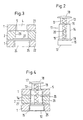
- FIG 3 the joint area of the gripping pliers according to Figure 1 approximately in a cross section along the line III-III shown in Figure 1.
- the clamp 1 points in this area an upper cheek 21 and a lower cheek 22 on.
- the upper cheek 21 carries the locking hole 4 with its overlapping holes 5, while the lower cheek 22 a corresponding locking hole 24 and overlapping bores 25 having.
- the pliers handle 2 runs in this Joint area between the two cheeks 21 and 22 of the Pliers bracket 1.
- the pliers handle 2 also has a round Through hole 26 on a radially transverse at one end is assigned via the bore 26 extending pin 27.
- the locking hole 4 is so with its overlapping holes 5 designed that the diameter of each hole 5 the Inner diameter of the bore 26 of the gripper arm 2 corresponds to, while in the overlap area two Adjacent holes 5 the clear cross section of the Rest hole 2 is narrowed.
- This design of a rest hole is generally known from adjustable water pump pliers.
- the locking hole 24 of the lower cheek 22 is in the clear width made larger. Here corresponds to Area of overlap between two bores 25 in its clear width of the bore diameter of the holes 5 and 26, while the actual bore diameter of the Bores 25 is larger than this.
- FIG. 4 finally shows the locking pin according to FIG. 2 (rotated 90 ° around its axis) according to the joint area Figure 3 used. Identify the same reference numbers components already described here.
- the locking pin 12 In the engagement position shown is the locking pin 12 its area 13 of smaller diameter outside the Forceps joint, while the area 14 middle Diameter a locking hole 5 and the bore 26 of the Pliers handle 2 interspersed.
- the pin 27 passes through the slot 20 of the locking pin 11, so that the coil spring 19 with one end against the pin 27 and can support against the head 18 with the other end. On in this way, the coil spring 19 tensions the locking pin 11 in the joint in this snap position.
- a shift of the locking pin in the axial direction simple amount of the thickness of a cheek 21 or 22 sufficient to completely unlock the pliers joint. If the pliers joint is dimensioned so that the same Each cheek can bear the same load on surfaces 21 and 22 are kept narrower in width than that Joint area of the forceps handle. For example, from the Total thickness of the joint each cheek 21 and 22 a quarter make up while the thickness of the forceps in this Area makes up half. With this configuration is so it is possible to increase the height of the area 13 by a quarter the total thickness of the joint in this area, so that the axial displacement for unlocking must be only a quarter of the thickness. Both known grippers with adjustable, lockable Maul is the required actuation path of the locking element each twice as large.
Landscapes
- Engineering & Computer Science (AREA)
- Mechanical Engineering (AREA)
- Gripping Jigs, Holding Jigs, And Positioning Jigs (AREA)
- Hand Tools For Fitting Together And Separating, Or Other Hand Tools (AREA)
- Portable Nailing Machines And Staplers (AREA)
Abstract
Description
Die vorliegende Erfindung betrifft eine Greifzange mit den
Merkmalen des Oberbegriffs des Anspruchs 1, die aus
DE 296 20 588 U bekannt ist.The present invention relates to a gripper with the
Features of the preamble of
Derartige Greifzangen sind aus der Praxis und insbesondere aus den Druckschriften DE-PS 805 265 sowie DE-92 18 069 U1 bekannt. Bei einer bekannten Greifzange kreuzen sich der Zangenstiel und der Zangenbügel in einem Gelenk, das ein längliches Rastloch umfaßt. Der Zangenstiel bildet dabei die im Gebrauch untere Zangenbacke sowie den oberen Griffhebel, während der Zangenbügel die im Gebrauch obere Zangenbacke und den unteren Griffhebel bildet.Such gripping pliers are from practice and in particular from the publications DE-PS 805 265 and DE-92 18 069 U1 known. In a known gripper, the cross Forceps handle and the forceps bracket in one joint, the one elongated locking hole includes. The forceps handle forms the lower jaw as well as the upper one Handle lever, while the pliers bracket is the upper one in use Pliers jaw and the lower handle lever forms.
Ein Zapfen, der die Lagerachse des Gelenks bildet, ist im Querschnitt sternförmig oder rund ausgebildet und greift in Längsrichtung des Langlochs formschlüssig in das im Zangenbügel befindliche Rastloch ein. Der Zapfen ist in seine Einraststellung von einer ungeschützt angebrachten Blattfeder vorgespannt, die sich auf der dem Zapfen gegenüberliegenden Außenseite des Gelenks befindet. Zum Verstellen der Maulweite der bekannten Greifzange ist der Zapfen gegen die Kraft der Blattfeder in das Zangengelenk einzudrücken, so daß sein größerer Querschnitt aus dem Rastloch herausgedrückt wird. Sodann kann der Zangenbügel gegen den Zangenstiel im gewünschten Maße verstellt werden. Sobald der Zapfen losgelassen wird, drückt die Blattfeder ihn in die Eingriffsstellung mit dem Rastloch, und die vorgesehene Maulweite der Greifzange wird fixiert. Bei dieser Greifzange ist der Zangenstiel geschlitzt und der Zangenbügel im Gelenkbereich durch den Zangenstiel hindurchgesteckt. Aus Stabilitätsgründen wird angestrebt, den Zangenbügel im Gelenkbereich etwa auf die Hälfte der Gesamtdicke zu bemessen, damit die tragenden Flächen der am Rastbolzen anliegenden Gelenkteile bei Zangenbügel und Zangenstiel etwa gleich groß sind.Bei der bekannten Greifzange ist es deshalb erforderlich, zur Lösung der Rastverbindung den Rastbolzen um einen etwa der halben Zangendicke entsprechenden Betrag quer zur Zangenlängsebene zu verlagern. Es wird dabei als nachteilig empfunden, daß dieser Weg relativ lang ist und das freie Betätigungsende des Rastbolzens in der Ruhestellung seitlich erheblich über das Gelenk hinausragt.A pin that forms the bearing axis of the joint is in the Cross-section shaped like a star or round and engages in Longitudinal direction of the slot in the im Pliers bracket a locking hole. The spigot is in its latched position from an unprotected one Leaf spring biased, which is on the the journal opposite the outside of the joint. To the Adjusting the mouth width of the known gripping pliers is the Pin against the force of the leaf spring in the pliers joint indent so that its larger cross section from the The locking hole is pushed out. Then the clamp can can be adjusted against the pliers handle to the desired extent. As soon as the pin is released, the leaf spring presses him in the engaged position with the locking hole, and the The intended jaw width of the gripper is fixed. at this gripper is the slotted handle and the Pliers bracket in the joint area through the pliers handle through put. For reasons of stability, the aim is the clamp in the joint area to about half of the Total thickness to be dimensioned so that the load-bearing surfaces of the am Locking pins on the joint parts on the clamp and Pliers handle are about the same size Gripping pliers it is therefore necessary to solve the Snap connection the locking pin by about half Pliers thickness corresponding amount across the longitudinal plane of the pliers to relocate. It is perceived as a disadvantage that this path is relatively long and the free actuation end the locking bolt laterally significantly in the rest position the joint protrudes.
Die DE 296 20 588 U zeigt eine ähnliche Greifzange wie die oben genannten Dokumente. In einer Ausführungsform ist beschrieben, dass der Zangenbügel geschlitzt und der Zangenstiel hindurchgesteckt sein kann. Die Ausbildung des Gelenks ist dabei nicht beschrieben.DE 296 20 588 U shows a gripper similar to that documents mentioned above. In one embodiment described that the pliers bracket slotted and the Pliers handle can be inserted. Training the The joint is not described.
Ausgehend hiervon ist es Aufgabe der Erfindung, eine Greifzange zu schaffen, bei der der Betätigungsweg des Rastbolzens kürzer ist.Based on this, it is an object of the invention to To create gripping pliers in which the operating path of the The locking pin is shorter.
Diese Aufgabe wird von einer Greifzange mit den Merkmalen
des Anspruchs 1 gelöst.This task is carried out by a gripper with the characteristics
of
Weil der Zangenbügel im Gelenkbereich geschlitzt ist und zwei längliche, sich quer zu der Zangenebene gegenüberliegende Rastlöcher aufweist und der Zangenstiel im Gelenkbereich durch den Zangenbügel hindurchgesteckt ist, kann das Einstellelement in dem geschlitzten Zangenbügel an zwei voneinander beabstandeten Stellen eingerastet werden. Hieraus ergibt sich die Möglichkeit, daß zwei relativ schmale Lagerflächen in dem geschlitzten Zangenbügel gebildet werden und die Verstellposition des Einstellelements erreicht wird, indem dieses um den Betrag einer Lagerflächenbreite quer zur Zangenlängsebene verlagert wird. Der Betätigungsweg für die Verstellung einer Greifzange mit einem derart gestalteten Gelenkbereich ist nur etwa halb so lang wie der bei herkömmlichen Greifzangen erforderliche Betätigungsweg.Because the clamp is slotted in the joint area and two elongated, opposite locking holes across the plane of the pliers has and the forceps handle in the joint area through the forceps bracket is inserted through, the adjusting element in the slotted tongs at two spaced apart Digits are snapped into place. Hence the Possibility that two relatively narrow storage areas in the slotted tongs are formed and the Adjustment position of the adjusting element is achieved by this by the amount of a storage area width across Pliers longitudinal plane is shifted. The path of activity for the Adjustment of a gripper with such a design The joint area is only about half as long as that at Conventional gripping pliers required actuation path.
Ein einfach zu fertigendes Einstellelement ergibt sich, wenn dieses einen im wesentlichen rotationssymmetrischen Raststift umfaßt. Der Raststift kann in seiner Eingriffsposition zugleich die Lagerachse des Gelenks bilden. Eine gute Lagerung ergibt sich weiterhin, wenn der Raststift einen ersten Bereich kleineren Durchmessers, einen zweiten Bereich mittleren Durchmessers und einen dritten Bereich größeren Durchmessers aufweist.An easy-to-manufacture adjustment element results if this one is essentially rotationally symmetrical Includes locking pin. The locking pin can be in its Position of engagement at the same time the bearing axis of the joint form. Good storage continues if the Locking pin a first area of smaller diameter, a second area of medium diameter and one has third area of larger diameter.
Eine besonders robuste Ausführungsform, die auch gegen Beschädigung und Verschmutzung unempfindlich ist, sieht vor, daß das eine Rastloch des Zangenbügels eine Anzahl von sich überlappenden, kleinen Rastbohrungen eines ersten Bohrungsdurchmessers aufweist und das andere Rastloch eine Anzahl von überlappenden großen Rastbohrungen eines zweiten größeren Bohrungsdurchmessers aufweist, wobei außerdem jeweils eine Bohrung ersten Durchmessers und eine Bohrung zweiten Durchmessers koaxial zueinander angeordnet sind. Diese Ausführungsform wird weiter dadurch verbessert, daß der Raststift in der Eingriffsposition mit seinem zweiten Bereich mittleren Durchmessers in eine Bohrung des ersten Rastlochs eingreift und mit seinem dritten Bereich großen Durchmessers in eine Bohrung des zweiten Rastlochs eingreift, so daß der Raststift in der Zangenebene formschlüssig fixiert ist, und der Raststift in der Verstellposition in seinem ersten Bereich kleinen Durchmessers längsverschieblich in das erste Rastloch eingreift und mit seinem zweiten Bereich mittleren Durchmessers längsverschieblich in das zweite Rastloch eingreift, so daß der Raststift in der Zangenebene in Längsrichtung der Rastlöcher insgesamt verschieblich ist.A particularly robust embodiment that also works against Damage and pollution is insensitive, looks before that the one locking hole of the pliers bracket a number of itself overlapping, small locking holes of a first Has bore diameter and the other Locking hole a number of overlapping large locking holes a second larger bore diameter, wherein also a hole of the first diameter and one Bore of second diameter arranged coaxially to one another are. This embodiment is further improved by that the locking pin in the engaged position with his second area of medium diameter in a bore of the engages the first locking hole and with its third area large diameter in a hole in the second locking hole engages so that the locking pin in the pliers plane is positively fixed, and the locking pin in the Adjustment position in its first area small Diameter longitudinally displaceable in the first locking hole engages and middle with its second area Diameter longitudinally displaceable in the second locking hole engages so that the locking pin in the plane of the pliers Overall length of the locking holes is displaceable.
Als Feder wird vorteilhaft eine Schraubenfeder vorgesehen, die in eine achsparallele Bohrung des Raststifts eingreift. Der Zangenstiel trägt als Widerlager im Bereich des Gelenks einen quer zu dem Raststift angeordneten Stift, gegen den die Feder abgestützt ist und der den Raststift durchsetzt. Mit diesem Stift wird der Raststift unverlierbar gesichert.A helical spring is advantageously provided as the spring, which engages in an axially parallel bore of the locking pin. The forceps handle acts as an abutment in the area of the joint a pin arranged transversely to the locking pin against which the spring is supported and which penetrates the locking pin. With this pin the locking pin is captively secured.
Schließlich ist von Vorteil, wenn der Raststift an seiner dem ersten Bereich benachbarten Stirnseite einen Verschluß aufweist, der die Bohrung für die Schraubenfeder nach außen verschließt.Finally, it is advantageous if the locking pin on his a closure adjacent the first area has the hole for the coil spring to the outside closes.
Im folgenden wird ein Ausführungsbeispiel der vorliegenden Erfindung anhand der Zeichnung veranschaulicht.The following is an embodiment of the present Invention illustrated with reference to the drawing.
Es zeigen:
- Fig. 1:
- Eine erfindungsgemäße Greifzange mit geschlitztem Bügel und durchgestecktem Stiel in einer Seitenansicht auf die Betätigungsseite des Raststifts;
- Fig. 2
- den Raststift in einem Querschnitt von der Seite;
- Fig. 3
- einen Querschnitt durch den Gelenkbereich der erfindungsgemäßen Greifzange in einer abgebrochenen Darstellung, sowie
- Fig. 4:
- den Raststift gemäß
Figur 2, eingesetzt in den Gelenkbereich gemäßFigur 3 in seiner Eingriffsstellung.
- Fig. 1:
- A gripping pliers according to the invention with slotted bracket and push-through handle in a side view of the actuating side of the locking pin;
- Fig. 2
- the locking pin in a cross section from the side;
- Fig. 3
- a cross section through the joint area of the gripping pliers according to the invention in a broken view, and
- Fig. 4:
- the locking pin according to Figure 2, inserted into the joint area according to Figure 3 in its engaged position.
Die Figur 1 zeigt eine erfindungsgemäße Greifzange mit
einem geschlitzten Zangenbügel 1 und einem durchgesteckten
Zangenstiel 2. Der Zangenbügel 1 trägt in seinem
geschlitzten Gelenkbereich 3 ein längliches Rastloch 4, das
bei diesem Ausführungsbeispiel von insgesamt 7 runden
Bohrungen 5 gebildet ist. Die Bohrungen 5 sind in einer
geraden Linie nebeneinander angeordnet und überlappen
teilweise. Außerdem trägt der Zangenbügel 1 eine obere
Zangenbacke 6 sowie einen im Gebrauch unteren
Griffabschnitt 7. Der Zangenstiel 2 trägt demgegenüber eine
untere Zangenbacke 8 sowie einen im Gebrauch oberen
Griffabschnitt 9. Zur Lagerung des Zangenstiels 2 in dem
Zangenbügel 1 ist ein Raststift 11 vorgesehen, der sowohl
den Zangenbügel 1 als auch den Zangenstiel 2 durchsetzt und
der in eingerasteter Stellung eine in dem Rastloch 4
unverschiebliche Lagerachse für den Zangenbügel 1 und den
Zangenstiel 2 bildet.Figure 1 shows a gripping pliers according to the invention
a slotted
Die Figur 2 zeigt den Raststift 11 in einer Seitenansicht.
Der Raststift 11 weist einen im wesentlichen
rotationssymmetrischen Grundkörper 12 auf. Dieser trägt
einen ersten Bereich 13 kleineren Durchmessers, einen an
den Bereich 13 anschließenden zweiten Bereich 14 mittleren
Durchmessers sowie einen an den Bereich 14 anschließenden
dritten Bereich 15 großen Durchmessers. Die Bereiche 13 und
14 sowie 14 und 15 sind jeweils über eine Fase 16
aneinander angefügt. Im Inneren des Raststifts 11 sitzt
mittig eine axiale Sackbohrung 17, die den Bereich 13 und
den Bereich 14 vollständig durchsetzt. Eine mit dem
Grundkörper 12 verschraubte oder verklebte Kappe 18
verschließt die Sackbohrung an ihrem offenen Ende. In die
Sackbohrung 17 ist eine Schraubenfeder 19 eingesetzt. Figure 2 shows the
Schließlich ist der Grundkörper 12 des Raststifts 11 quer,
d. h. in radialer Richtung, von einem Langloch 20
durchsetzt.Finally, the
In der Figur 3 ist der Gelenkbereich der Greifzange gemäß
Figur 1 etwa in einem Querschnitt entlang der Linie III-III
aus der Figur 1 dargestellt. Der Zangenbügel 1 weist in
diesem Bereich eine obere Wange 21 sowie eine untere Wange
22 auf. Die obere Wange 21 trägt das Rastloch 4 mit seinen
überlappenden Bohrungen 5, während die untere Wange 22 ein
entsprechendes Rastloch 24 sowie überlappende Bohrungen 25
aufweist. Der Zangenstiel 2 verläuft in diesem
Gelenkbereich zwischen den beiden Wangen 21 und 22 des
Zangenbügels 1. Der Zangenstiel 2 weist außerdem eine runde
Durchgangsbohrung 26 auf, der an einem Ende ein radial quer
über die Bohrung 26 verlaufender Stift 27 zugeordnet ist.In Figure 3, the joint area of the gripping pliers according to
Figure 1 approximately in a cross section along the line III-III
shown in Figure 1. The
Das Rastloch 4 ist mit seinen überlappenden Bohrungen 5 so
gestaltet, daß der Durchmesser einer jeden Bohrung 5 dem
Innendurchmesser der Bohrung 26 des Zangenstiels 2
entspricht, während in dem Überlappungsbereich je zwei
benachbarter Bohrungen 5 der lichte Querschnitt des
Rastlochs 2 verengt ist. Diese Gestaltung eines Rastlochs
ist von verstellbaren Wasserpumpenzangen allgemein bekannt.
Das Rastloch 24 der unteren Wange 22 ist jedoch in der
lichten Weite größer gestaltet. Hier entspricht der
Überlappungsbereich zwischen je zwei Bohrungen 25 in seiner
lichten Weite dem Bohrungsdurchmesser der Bohrungen 5 und
26, während der eigentliche Bohrungsdurchmesser der
Bohrungen 25 größer ist als diese.The locking
Die Figur 4 zeigt schließlich den Raststift gemäß Figur 2
(um 90° um seine Achse gedreht) in den Gelenkbereich gemäß
Figur 3 eingesetzt. Gleiche Bezugsziffern kennzeichnen
hierbei bereits beschriebene Bauelemente. In der
dargestellten Eingriffsposition liegt der Raststift 12 mit
seinem Bereich 13 kleineren Durchmessers außerhalb des
Zangengelenks, während der Bereich 14 mittleren
Durchmessers ein Rastloch 5 sowie die Bohrung 26 des
Zangenstiels 2 durchsetzt. Der Bereich 15 hingegen liegt in
einer Bohrung 25 des Zangenbügels 1 ein. Der Stift 27
durchsetzt das Langloch 20 des Rastbolzens 11, so daß sich
die Schraubenfeder 19 mit einem Ende gegen den Stift 27 und
mit dem anderen Ende gegen den Kopf 18 abstützen kann. Auf
diese Weise spannt die Schraubenfeder 19 den Rastbolzen 11
in dem Gelenk in diese Einrastposition vor.FIG. 4 finally shows the locking pin according to FIG. 2
(rotated 90 ° around its axis) according to the joint area
Figure 3 used. Identify the same reference numbers
components already described here. In the
engagement position shown is the locking
Zur Verstellung der Maulweite der dargestellten Greifzange
wird ein axialer Druck auf dem Kopf 18 des Rastbolzens 11
ausgeübt, so daß der Rastbolzen 11 gegen die Spannung der
Schraubenfeder 19 verlagert wird. Dabei tritt der Bereich
15 größeren Durchmessers aus der Bohrung 25 aus, der
Bereich 14 mittleren Durchmessers wird aus der Bohrung 5 in
die Bohrung 25 verlagert, während er nach wie vor in der
Bohrung 26 des Zangenstiels einliegt. Der Bereich 13
kleineren Durchmessers tritt anstelle des Bereichs 14 in
die Bohrung 5 ein. Da nunmehr die jeweils nächstkleineren
Bereiche 14 bzw. 15 statt der Bereiche 15 bzw. 14 in den
Rastlöchern 4 bzw. 24 einliegen, kann der Rastbolzen in
Längsrichtung der Rastlöcher 4, 24 verlagert werden, um so
in die gewünschte Position gebracht zu werden. Wird nun der
Druck auf den Kopf 18 des Rastbolzens 11 verringert, so
spannt die Schraubenfeder 19 den Rastbolzen wieder in seine
Eingriffsposition vor, wobei die Bereiche 14 und 15 in die
ausgewählten Bohrungen 5 und 25 der Rastlöcher 4 und 24
einrasten. Die Fasen 16 erleichtern bei nicht genauer
Überdeckung der Bohrungsachsen das Einführen des
Rastbolzens in die jeweiligen Bohrungen. In der
Eingriffsposition ist nun das Gelenk in Richtung der
Rastlöcher 4 und 24 unverschieblich gesichert. To adjust the jaw width of the gripping pliers shown
there is an axial pressure on the
Weiter ist aus diesem Ausführungsbeispiel ersichtlich, daß
eine Verlagerung des Rastbolzens in axialer Richtung um den
einfachen Betrag der Dicke einer Wange 21 bzw. 22
ausreicht, um das Zangengelenk vollständig zu entriegeln.
Wenn das Zangengelenk so dimensioniert ist, daß gleiche
Flächen jeweils gleiche Lasten tragen, so kann jede Wange
21 bzw. 22 in ihrer Breite schmaler gehalten werden als der
Gelenkbereich des Zangenstiels. Beispielsweise kann von der
Gesamtdicke des Gelenks jede Wange 21 und 22 ein Viertel
ausmachen, während die Dicke des Zangenstiels in diesem
Bereich die Hälfte ausmacht. Bei dieser Konfiguration ist
es also möglich, die Höhe des Bereichs 13 mit einem Viertel
der Gesamtdicke des Gelenks in diesem Bereich anzusetzen,
so daß auch die axiale Verlagerung zur Entriegelung
lediglich ein Viertel der Dicke betragen muß. Bei den
bekannten Greifzangen mit verstellbarem, verriegelbarem
Maul ist der benötigte Betätigungsweg des Rastelements
jeweils doppelt so groß.Furthermore, it can be seen from this embodiment that
a shift of the locking pin in the axial direction
simple amount of the thickness of a
Claims (8)
- Gripping pliers with a plier handle (2) and a plier clamp (1), which both comprise a gripping section (9,7) and jaws (8,6) opposite the gripping section (9,7), wherein the plier handle (2) and the plier clamp (1) are rotatably mounted on a pivot in a joint put through them and the joint comprises a gripping position and an adjusting position, wherein furthermore the joint can be manually displaced toward the pivot against a spring (19) and the stop pin (11) forming the joint for setting the gripping position and the adjusting position is provided, and wherein the plier clamp (1) is slotted into the joint area and the plier handle (2) is put through the joint area by the plier clamp (1), characterised in that the plier clamp (1) in the joint area comprises two oblong ratchet holes (4,24) placed diagonally opposite to the level of the pliers.
- Gripping pliers as claimed in claim 1, characterised in that the stop pin (11) is essentially axially symmetrical.
- Gripping pliers as claimed in one of the foregoing claims, characterised in that the stop pin (11) comprises a first area (13) of a smaller diameter, a second area (14) of medium diameter and a third area (15) of a larger diameter.
- Gripping pliers as claimed in one of the foregoing claims, characterised in that the one ratchet hole (4) comprises a number of overlapping small ratchet bores (5) of a small bore diameter and the other ratchet hole (24) comprises a number of overlapping large ratchet bores (25) of a second larger bore diameter, wherein furthermore both a bore (5) of a first diameter and a bore (25) of a second diameter are arranged axially to each other.
- Gripping pliers as claimed in one of the foregoing claims, characterised in that the stop pin (11) engages in the gripping position with its second area (14) of medium diameter in a bore (5) of the first ratchet hole and engages in a bore (25) of the second ratchet hole (24) with its third area (15) of large diameter, in order that the stop pin (11) is fixed positively in the level of the pliers, and that the stop pin (11) engages so as to be adjustable lengthways in the adjusting position with its first area (13) of small diameter in the second ratchet hole (24), so that the stop pin (11) can be adjusted lengthways in the gripping level of the ratchet hole (24).
- Gripping pliers as claimed in one of the foregoing claims, characterised in that a screw spring is provided as a spring (19), which engages in an axially-parallel bore (17) of the stop pin (11).
- Gripping pliers as claimed in one of the foregoing claims, characterised in that the plier handle (2) bears a pin (27) arranged diagonally to the stop pin (11) in the joint area, against which pin (27) the spring (19) is supported and the stop pin (11) is thereby pushed through.
- Gripping pliers as claimed in one of the foregoing claims, characterised in that the stop pin (11) comprises a lock (18) on its neighbouring front side in the first area (13), said lock locking the bore (17) outwards.
Applications Claiming Priority (3)
| Application Number | Priority Date | Filing Date | Title |
|---|---|---|---|
| DE19741796A DE19741796A1 (en) | 1997-09-22 | 1997-09-22 | Push-through gripping pliers with adjustable jaw width |
| DE19741796 | 1997-09-22 | ||
| US09/392,962 US6318217B1 (en) | 1997-09-22 | 1999-09-09 | Through-bolt gripping pliers with adjustable opening width |
Publications (3)
| Publication Number | Publication Date |
|---|---|
| EP0904898A2 EP0904898A2 (en) | 1999-03-31 |
| EP0904898A3 EP0904898A3 (en) | 2000-04-26 |
| EP0904898B1 true EP0904898B1 (en) | 2003-04-09 |
Family
ID=26040203
Family Applications (1)
| Application Number | Title | Priority Date | Filing Date |
|---|---|---|---|
| EP98113066A Expired - Lifetime EP0904898B1 (en) | 1997-09-22 | 1998-07-14 | Wrench with variable opening and interlocking arms |
Country Status (5)
| Country | Link |
|---|---|
| US (1) | US6318217B1 (en) |
| EP (1) | EP0904898B1 (en) |
| AT (1) | ATE236763T1 (en) |
| DE (2) | DE19741796A1 (en) |
| ES (1) | ES2255118T3 (en) |
Families Citing this family (26)
| Publication number | Priority date | Publication date | Assignee | Title |
|---|---|---|---|---|
| FR2786119B1 (en) * | 1998-11-19 | 2001-02-09 | Bost Garnache Ind | CLAMP WITH AT LEAST TWO ADJUSTMENT POSITIONS |
| FR2811925B1 (en) * | 2000-07-19 | 2003-01-24 | Facom | MULTIPRISE PLIERS |
| USRE45680E1 (en) * | 2000-07-19 | 2015-09-29 | Stanley Works (Europe) Gmbh | Transversely retained multiple slip-joint pliers |
| US20040194317A1 (en) * | 2003-01-27 | 2004-10-07 | Pippert Aaron J. | Adjustable nut cracker |
| GB2400065B (en) * | 2003-04-02 | 2006-04-12 | Irwin Ind Tool Co | Quick adjusting pliers |
| US7100480B2 (en) * | 2003-04-02 | 2006-09-05 | Irwin Industrial Tool Company | Quick adjusting pliers |
| DE202004012362U1 (en) * | 2004-08-06 | 2004-10-14 | Eduard Wille Gmbh & Co. Kg | pliers |
| USD543812S1 (en) | 2004-11-05 | 2007-06-05 | Irwin Industrial Tool Company | Groovelock tool |
| ES2277520B1 (en) * | 2005-06-01 | 2008-05-16 | Rothenberger, S.A. | PINCERS. |
| US7174816B1 (en) * | 2005-07-26 | 2007-02-13 | Helen Of Troy Limited | Visual alignment features for adjusting tongue and groove pliers |
| USD589315S1 (en) * | 2007-05-30 | 2009-03-31 | Knipex-Werk C. Gustav Putsch Kg | Pliers |
| USD588890S1 (en) * | 2007-11-27 | 2009-03-24 | Rothenberger, S.A. | Pliers |
| US7681477B2 (en) * | 2008-01-31 | 2010-03-23 | The Stanley Works | Adjustable pliers |
| US7861622B2 (en) * | 2008-07-28 | 2011-01-04 | Irwin Industrial Tool Company | Locking pliers |
| US20100018364A1 (en) * | 2008-07-28 | 2010-01-28 | Irwin Industrial Tool Company | Quick adjusting multi-position pliers |
| US20100018362A1 (en) * | 2008-07-28 | 2010-01-28 | Irwin Industrial Tool Company | Locking pliers |
| USD635428S1 (en) | 2009-08-21 | 2011-04-05 | Irwin Industrial Tool Company | Locking pliers jaw |
| USD635427S1 (en) | 2009-08-21 | 2011-04-05 | Irwin Industrial Tool Company | Locking pliers jaw |
| USD782891S1 (en) | 2015-04-02 | 2017-04-04 | Milwaukee Electric Tool Corporation | Locking pliers |
| CN104874656B (en) * | 2015-05-29 | 2017-01-25 | 清华大学 | Self-adaptive rapid pipe clamp |
| GB2540621A (en) * | 2015-07-24 | 2017-01-25 | Stanley Works (Europe) Ag | Adjustable pliers |
| US11911879B1 (en) * | 2016-09-06 | 2024-02-27 | Ector Cantu Gomez | Chrome flush valve installation tool |
| CN108581906A (en) * | 2018-05-11 | 2018-09-28 | 杭州临安制钳有限公司 | a kind of adjustable spanner |
| TWI680037B (en) * | 2018-12-28 | 2019-12-21 | 游再順 | Plier with a capability to unlock easily |
| TWI727803B (en) * | 2020-05-20 | 2021-05-11 | 王衍裕 | Tool jaw width adjustment structure |
| US11691249B2 (en) | 2020-07-29 | 2023-07-04 | Snap-On Incorporated | Push button release mechanism for pliers |
Family Cites Families (14)
| Publication number | Priority date | Publication date | Assignee | Title |
|---|---|---|---|---|
| DE1600360U (en) * | 1948-10-29 | 1950-02-02 | Ver Beckersche Werkzeugfab | WATER PUMP PLIERS. |
| DE805265C (en) * | 1948-11-04 | 1951-05-10 | Walter Gott Gesenkschmiede Und | Pliers |
| FR2052020A5 (en) * | 1969-07-11 | 1971-04-09 | Stephanoises Forges | |
| US4269089A (en) * | 1978-11-24 | 1981-05-26 | Hastings Charles E | Adjustable ratchet pliers |
| US4232573A (en) * | 1979-01-08 | 1980-11-11 | Dace Jr Marvin H | Slip pliers with lock |
| US4296655A (en) * | 1980-05-12 | 1981-10-27 | Joseph Tesoro | Slip joint pliers |
| DE3460942D1 (en) * | 1983-02-02 | 1986-11-20 | Putsch Gustav Knipex Werk | Gripping plyers |
| GB8506017D0 (en) * | 1985-03-08 | 1985-04-11 | Stafford M A | Adjustable wrench |
| JPH0435096Y2 (en) * | 1985-11-02 | 1992-08-20 | ||
| US4773288A (en) * | 1987-06-08 | 1988-09-27 | Jang Young H | Adjustable vise grip |
| DE9218069U1 (en) * | 1991-08-08 | 1993-07-29 | Knipex-Werk C. Gustav Putsch, 5600 Wuppertal | Pliers with two jaws |
| DE9109863U1 (en) * | 1991-08-09 | 1991-10-17 | U.S.H.-Fittings + Kunststoffteile GmbH, 4815 Schloß Holte-Stukenbrock | Water pump pliers |
| SE9402978L (en) * | 1994-09-07 | 1995-12-04 | Kent Lundell | Methods and apparatus for dismantling moldings, preferably window moldings snap-fit on a frame, and method for manufacturing the apparatus |
| DE19634082A1 (en) * | 1996-08-23 | 1998-02-26 | Ver Beckersche Werkzeugfab | Gripping pliers with adjustable jaw width |
-
1997
- 1997-09-22 DE DE19741796A patent/DE19741796A1/en not_active Withdrawn
-
1998
- 1998-07-14 EP EP98113066A patent/EP0904898B1/en not_active Expired - Lifetime
- 1998-07-14 AT AT98113066T patent/ATE236763T1/en not_active IP Right Cessation
- 1998-07-14 DE DE59807825T patent/DE59807825D1/en not_active Expired - Fee Related
- 1998-07-14 ES ES98113066T patent/ES2255118T3/en not_active Expired - Lifetime
-
1999
- 1999-09-09 US US09/392,962 patent/US6318217B1/en not_active Expired - Fee Related
Also Published As
| Publication number | Publication date |
|---|---|
| DE59807825D1 (en) | 2003-05-15 |
| EP0904898A3 (en) | 2000-04-26 |
| DE19741796A1 (en) | 1999-03-25 |
| EP0904898A2 (en) | 1999-03-31 |
| US6318217B1 (en) | 2001-11-20 |
| ES2255118T3 (en) | 2006-06-16 |
| ATE236763T1 (en) | 2003-04-15 |
Similar Documents
| Publication | Publication Date | Title |
|---|---|---|
| EP0904898B1 (en) | Wrench with variable opening and interlocking arms | |
| DE10138079A1 (en) | Placeholder with variable axial length | |
| EP1623796B1 (en) | Pliers | |
| EP1394012B1 (en) | Locking device for two members being movable relative to each other | |
| DE2916242C2 (en) | Security arrangement for doors, windows or the like. | |
| DE3023882C2 (en) | ||
| DE3813342A1 (en) | CLAMPING DEVICE | |
| DE60038654T2 (en) | Clamping bracket for support and connection elements | |
| EP0309880B1 (en) | Hand tool | |
| DE2931873A1 (en) | Hinged fitment for adjustable seat backrest - is used in vehicle and consists of locking slide piece with cogged segment, concentric with pivot axle | |
| EP0824996A1 (en) | Wrench with adjustable opening | |
| DE29505752U1 (en) | Device for connecting plates by means of screwing | |
| DE3632026C2 (en) | ||
| DE4412056C2 (en) | Cable lock | |
| DE69205974T2 (en) | DEVICE FOR ALTERNATIVE CONTROL OF TWO INTERACTING VALVES, ESPECIALLY SAFETY VALVES ON PRESSURE BOILERS. | |
| DE3005692A1 (en) | Folding ladder hinge mechanism - has control piece guide face bounding short pin recess for stop piece | |
| DE19904713C1 (en) | Axial fixing motor vehicle gear change linkage has pin with sprung retaining ring for lever on pin | |
| DE2321346C3 (en) | Articulated fitting for foldable ladders | |
| WO1993003248A1 (en) | Holding device, especially for motor vehicle door hinges | |
| DE4211796C2 (en) | Device for connecting and locking two elements | |
| DE1258758B (en) | Detachable door handle clamp fastening adjustable to any door thickness | |
| DE29518029U1 (en) | Hand scissors | |
| DE10314291A1 (en) | Load engaging hook with shortening claw, has specific arrangement of final and penultimate chain links relative to claw jaws | |
| DE10301687B3 (en) | Holder used for holding the cheek in surgical interventions in the jaw region comprises two jaws, a locking device, and a holding part for holding the cheek in a position away from the jaws | |
| WO2002008616A1 (en) | Screw |
Legal Events
| Date | Code | Title | Description |
|---|---|---|---|
| PUAI | Public reference made under article 153(3) epc to a published international application that has entered the european phase |
Free format text: ORIGINAL CODE: 0009012 |
|
| AK | Designated contracting states |
Kind code of ref document: A2 Designated state(s): AT BE CH DE DK FR GB IT LI NL |
|
| AX | Request for extension of the european patent |
Free format text: AL;LT;LV;MK;RO;SI |
|
| PUAL | Search report despatched |
Free format text: ORIGINAL CODE: 0009013 |
|
| AK | Designated contracting states |
Kind code of ref document: A3 Designated state(s): AT BE CH CY DE DK ES FI FR GB GR IE IT LI LU MC NL PT SE |
|
| AX | Request for extension of the european patent |
Free format text: AL;LT;LV;MK;RO;SI |
|
| 17P | Request for examination filed |
Effective date: 20000628 |
|
| 111L | Licence recorded |
Free format text: 20000512 0100 FACOM * 20000725 0101 BOST GARNACHE INDUSTRIES (GBI) |
|
| AKX | Designation fees paid |
Free format text: AT BE CH DE DK FR GB IT LI NL |
|
| 17Q | First examination report despatched |
Effective date: 20011203 |
|
| GRAH | Despatch of communication of intention to grant a patent |
Free format text: ORIGINAL CODE: EPIDOS IGRA |
|
| GRAH | Despatch of communication of intention to grant a patent |
Free format text: ORIGINAL CODE: EPIDOS IGRA |
|
| GRAA | (expected) grant |
Free format text: ORIGINAL CODE: 0009210 |
|
| AK | Designated contracting states |
Designated state(s): AT BE CH DE DK FR GB IT LI NL |
|
| PG25 | Lapsed in a contracting state [announced via postgrant information from national office to epo] |
Ref country code: SE Free format text: LAPSE BECAUSE OF FAILURE TO SUBMIT A TRANSLATION OF THE DESCRIPTION OR TO PAY THE FEE WITHIN THE PRESCRIBED TIME-LIMIT Effective date: 20030409 Ref country code: LU Free format text: LAPSE BECAUSE OF FAILURE TO SUBMIT A TRANSLATION OF THE DESCRIPTION OR TO PAY THE FEE WITHIN THE PRESCRIBED TIME-LIMIT Effective date: 20030409 Ref country code: IE Free format text: LAPSE BECAUSE OF FAILURE TO SUBMIT A TRANSLATION OF THE DESCRIPTION OR TO PAY THE FEE WITHIN THE PRESCRIBED TIME-LIMIT Effective date: 20030409 Ref country code: CY Free format text: LAPSE BECAUSE OF FAILURE TO SUBMIT A TRANSLATION OF THE DESCRIPTION OR TO PAY THE FEE WITHIN THE PRESCRIBED TIME-LIMIT Effective date: 20030409 |
|
| REG | Reference to a national code |
Ref country code: GB Ref legal event code: FG4D Free format text: NOT ENGLISH |
|
| REG | Reference to a national code |
Ref country code: CH Ref legal event code: EP |
|
| PG25 | Lapsed in a contracting state [announced via postgrant information from national office to epo] |
Ref country code: DK Free format text: LAPSE BECAUSE OF FAILURE TO SUBMIT A TRANSLATION OF THE DESCRIPTION OR TO PAY THE FEE WITHIN THE PRESCRIBED TIME-LIMIT Effective date: 20030709 |
|
| PG25 | Lapsed in a contracting state [announced via postgrant information from national office to epo] |
Ref country code: AT Free format text: LAPSE BECAUSE OF NON-PAYMENT OF DUE FEES Effective date: 20030714 |
|
| PG25 | Lapsed in a contracting state [announced via postgrant information from national office to epo] |
Ref country code: FI Free format text: LAPSE BECAUSE OF NON-PAYMENT OF DUE FEES Effective date: 20030731 Ref country code: BE Free format text: LAPSE BECAUSE OF NON-PAYMENT OF DUE FEES Effective date: 20030731 |
|
| GBT | Gb: translation of ep patent filed (gb section 77(6)(a)/1977) |
Effective date: 20030724 |
|
| PG25 | Lapsed in a contracting state [announced via postgrant information from national office to epo] |
Ref country code: MC Free format text: LAPSE BECAUSE OF NON-PAYMENT OF DUE FEES Effective date: 20031231 |
|
| ET | Fr: translation filed | ||
| BERE | Be: lapsed |
Owner name: VEREINIGTE BECKERSCHE WERKZEUGFABRIKEN G.M.B.H. & Effective date: 20030731 |
|
| PLBE | No opposition filed within time limit |
Free format text: ORIGINAL CODE: 0009261 |
|
| STAA | Information on the status of an ep patent application or granted ep patent |
Free format text: STATUS: NO OPPOSITION FILED WITHIN TIME LIMIT |
|
| 26N | No opposition filed |
Effective date: 20040112 |
|
| RBV | Designated contracting states (corrected) |
Designated state(s): AT BE CH CY DE DK ES FI FR GB GR IE IT LI LU MC NL PT SE |
|
| REG | Reference to a national code |
Ref country code: IE Ref legal event code: FG4D Free format text: GERMAN Ref country code: IE Ref legal event code: FD4D |
|
| REG | Reference to a national code |
Ref country code: ES Ref legal event code: FG2A Ref document number: 2255118 Country of ref document: ES Kind code of ref document: T3 |
|
| REG | Reference to a national code |
Ref country code: ES Ref legal event code: FD2A Effective date: 20030715 |
|
| PG25 | Lapsed in a contracting state [announced via postgrant information from national office to epo] |
Ref country code: PT Free format text: LAPSE BECAUSE OF NON-PAYMENT OF DUE FEES Effective date: 20030909 |
|
| PG25 | Lapsed in a contracting state [announced via postgrant information from national office to epo] |
Ref country code: GR Free format text: LAPSE BECAUSE OF NON-PAYMENT OF DUE FEES Effective date: 20030409 |
|
| PGFP | Annual fee paid to national office [announced via postgrant information from national office to epo] |
Ref country code: FR Payment date: 20090720 Year of fee payment: 12 Ref country code: ES Payment date: 20090724 Year of fee payment: 12 |
|
| PGFP | Annual fee paid to national office [announced via postgrant information from national office to epo] |
Ref country code: NL Payment date: 20090724 Year of fee payment: 12 Ref country code: GB Payment date: 20090724 Year of fee payment: 12 Ref country code: DE Payment date: 20090702 Year of fee payment: 12 Ref country code: CH Payment date: 20090727 Year of fee payment: 12 |
|
| PGFP | Annual fee paid to national office [announced via postgrant information from national office to epo] |
Ref country code: IT Payment date: 20090727 Year of fee payment: 12 |
|
| REG | Reference to a national code |
Ref country code: NL Ref legal event code: V1 Effective date: 20110201 |
|
| REG | Reference to a national code |
Ref country code: CH Ref legal event code: PL |
|
| GBPC | Gb: european patent ceased through non-payment of renewal fee |
Effective date: 20100714 |
|
| REG | Reference to a national code |
Ref country code: FR Ref legal event code: ST Effective date: 20110331 |
|
| PG25 | Lapsed in a contracting state [announced via postgrant information from national office to epo] |
Ref country code: CH Free format text: LAPSE BECAUSE OF NON-PAYMENT OF DUE FEES Effective date: 20100731 Ref country code: DE Free format text: LAPSE BECAUSE OF NON-PAYMENT OF DUE FEES Effective date: 20110201 Ref country code: LI Free format text: LAPSE BECAUSE OF NON-PAYMENT OF DUE FEES Effective date: 20100731 |
|
| REG | Reference to a national code |
Ref country code: DE Ref legal event code: R119 Ref document number: 59807825 Country of ref document: DE Effective date: 20110201 |
|
| PG25 | Lapsed in a contracting state [announced via postgrant information from national office to epo] |
Ref country code: NL Free format text: LAPSE BECAUSE OF NON-PAYMENT OF DUE FEES Effective date: 20110201 Ref country code: FR Free format text: LAPSE BECAUSE OF NON-PAYMENT OF DUE FEES Effective date: 20100802 Ref country code: IT Free format text: LAPSE BECAUSE OF NON-PAYMENT OF DUE FEES Effective date: 20100714 |
|
| PG25 | Lapsed in a contracting state [announced via postgrant information from national office to epo] |
Ref country code: GB Free format text: LAPSE BECAUSE OF NON-PAYMENT OF DUE FEES Effective date: 20100714 |
|
| REG | Reference to a national code |
Ref country code: ES Ref legal event code: FD2A Effective date: 20110818 |
|
| PG25 | Lapsed in a contracting state [announced via postgrant information from national office to epo] |
Ref country code: ES Free format text: LAPSE BECAUSE OF NON-PAYMENT OF DUE FEES Effective date: 20100715 |