EP0902422B1 - Schreiben von Servospuren auf einer Platte - Google Patents
Schreiben von Servospuren auf einer Platte Download PDFInfo
- Publication number
- EP0902422B1 EP0902422B1 EP98101859A EP98101859A EP0902422B1 EP 0902422 B1 EP0902422 B1 EP 0902422B1 EP 98101859 A EP98101859 A EP 98101859A EP 98101859 A EP98101859 A EP 98101859A EP 0902422 B1 EP0902422 B1 EP 0902422B1
- Authority
- EP
- European Patent Office
- Prior art keywords
- disk
- head
- data
- servo
- actuator
- Prior art date
- Legal status (The legal status is an assumption and is not a legal conclusion. Google has not performed a legal analysis and makes no representation as to the accuracy of the status listed.)
- Expired - Lifetime
Links
Images


Classifications
-
- G—PHYSICS
- G11—INFORMATION STORAGE
- G11B—INFORMATION STORAGE BASED ON RELATIVE MOVEMENT BETWEEN RECORD CARRIER AND TRANSDUCER
- G11B5/00—Recording by magnetisation or demagnetisation of a record carrier; Reproducing by magnetic means; Record carriers therefor
- G11B5/48—Disposition or mounting of heads or head supports relative to record carriers ; arrangements of heads, e.g. for scanning the record carrier to increase the relative speed
- G11B5/54—Disposition or mounting of heads or head supports relative to record carriers ; arrangements of heads, e.g. for scanning the record carrier to increase the relative speed with provision for moving the head into or out of its operative position or across tracks
- G11B5/55—Track change, selection or acquisition by displacement of the head
- G11B5/5521—Track change, selection or acquisition by displacement of the head across disk tracks
- G11B5/5526—Control therefor; circuits, track configurations or relative disposition of servo-information transducers and servo-information tracks for control thereof
- G11B5/553—Details
- G11B5/5534—Initialisation, calibration, e.g. cylinder "set-up"
-
- G—PHYSICS
- G11—INFORMATION STORAGE
- G11B—INFORMATION STORAGE BASED ON RELATIVE MOVEMENT BETWEEN RECORD CARRIER AND TRANSDUCER
- G11B5/00—Recording by magnetisation or demagnetisation of a record carrier; Reproducing by magnetic means; Record carriers therefor
- G11B5/012—Recording on, or reproducing or erasing from, magnetic disks
-
- G—PHYSICS
- G11—INFORMATION STORAGE
- G11B—INFORMATION STORAGE BASED ON RELATIVE MOVEMENT BETWEEN RECORD CARRIER AND TRANSDUCER
- G11B5/00—Recording by magnetisation or demagnetisation of a record carrier; Reproducing by magnetic means; Record carriers therefor
- G11B5/48—Disposition or mounting of heads or head supports relative to record carriers ; arrangements of heads, e.g. for scanning the record carrier to increase the relative speed
- G11B5/54—Disposition or mounting of heads or head supports relative to record carriers ; arrangements of heads, e.g. for scanning the record carrier to increase the relative speed with provision for moving the head into or out of its operative position or across tracks
- G11B5/55—Track change, selection or acquisition by displacement of the head
- G11B5/5521—Track change, selection or acquisition by displacement of the head across disk tracks
- G11B5/5526—Control therefor; circuits, track configurations or relative disposition of servo-information transducers and servo-information tracks for control thereof
-
- G—PHYSICS
- G11—INFORMATION STORAGE
- G11B—INFORMATION STORAGE BASED ON RELATIVE MOVEMENT BETWEEN RECORD CARRIER AND TRANSDUCER
- G11B5/00—Recording by magnetisation or demagnetisation of a record carrier; Reproducing by magnetic means; Record carriers therefor
- G11B5/48—Disposition or mounting of heads or head supports relative to record carriers ; arrangements of heads, e.g. for scanning the record carrier to increase the relative speed
- G11B5/58—Disposition or mounting of heads or head supports relative to record carriers ; arrangements of heads, e.g. for scanning the record carrier to increase the relative speed with provision for moving the head for the purpose of maintaining alignment of the head relative to the record carrier during transducing operation, e.g. to compensate for surface irregularities of the latter or for track following
- G11B5/596—Disposition or mounting of heads or head supports relative to record carriers ; arrangements of heads, e.g. for scanning the record carrier to increase the relative speed with provision for moving the head for the purpose of maintaining alignment of the head relative to the record carrier during transducing operation, e.g. to compensate for surface irregularities of the latter or for track following for track following on disks
- G11B5/59633—Servo formatting
- G11B5/59638—Servo formatting apparatuses, e.g. servo-writers
-
- G—PHYSICS
- G11—INFORMATION STORAGE
- G11B—INFORMATION STORAGE BASED ON RELATIVE MOVEMENT BETWEEN RECORD CARRIER AND TRANSDUCER
- G11B20/00—Signal processing not specific to the method of recording or reproducing; Circuits therefor
- G11B20/10—Digital recording or reproducing
- G11B20/12—Formatting, e.g. arrangement of data block or words on the record carriers
- G11B20/1217—Formatting, e.g. arrangement of data block or words on the record carriers on discs
-
- G—PHYSICS
- G11—INFORMATION STORAGE
- G11B—INFORMATION STORAGE BASED ON RELATIVE MOVEMENT BETWEEN RECORD CARRIER AND TRANSDUCER
- G11B20/00—Signal processing not specific to the method of recording or reproducing; Circuits therefor
- G11B20/10—Digital recording or reproducing
- G11B20/12—Formatting, e.g. arrangement of data block or words on the record carriers
- G11B2020/1264—Formatting, e.g. arrangement of data block or words on the record carriers wherein the formatting concerns a specific kind of data
- G11B2020/1265—Control data, system data or management information, i.e. data used to access or process user data
- G11B2020/1281—Servo information
- G11B2020/1282—Servo information in embedded servo fields
-
- G—PHYSICS
- G11—INFORMATION STORAGE
- G11B—INFORMATION STORAGE BASED ON RELATIVE MOVEMENT BETWEEN RECORD CARRIER AND TRANSDUCER
- G11B2220/00—Record carriers by type
- G11B2220/20—Disc-shaped record carriers
- G11B2220/25—Disc-shaped record carriers characterised in that the disc is based on a specific recording technology
- G11B2220/2508—Magnetic discs
- G11B2220/2516—Hard disks
Definitions
- the present invention relates to a disk unit for reading out servo data from a disk, positioning a head by actuating an actuator, and executing read/write of data from/in the disk, and to a servo track write system as well as a servo track write method.
- minimization, higher performance and cost reduction of a disk unit as an external storage for a computer have been required. Therefore, in order to realize cost reduction, it is important to improve quality of products as well as to enhance yield of the products.
- Fig. 14 is a cross-sectional view schematically showing configuration of a conventional type of disk unit which is mounted on a servo track writer.
- designated at the reference numeral 41 is a base, at 42 a disk, at 43 a spindle motor, at 44 a head actuator mounting the head thereon, at 45 a voice coil motor, at 51 a stage, at 52 a clock head, at 53 an actuator for a pin pick, and at 54 a pin pick.
- a magnetic disk is used for the disk 42 as one example herein.
- a disk unit is a type having a base cover
- almost all components of the disk unit excluding a cover (not shown) and a printed board (not shown) are assembled on the base 41, and the assembled components are fixed to the stage 51 of the servo track writer.
- the clock head 52 dedicated to writing/reading of a reference clock is loaded on one face of the disk 42 (e.g. on the top surface of the uppermost disk as shown in the figure), and on the other hand the actuator 53 for a pip pick for the servo track writer, which is a different body from the head actuator 44 for the disk unit itself, presses down a movable section of the head actuator 44 for the disk unit itself via the pin pick 54. For this reason, operations for positioning and moving the movable section of the head actuator 44 are executed for each track, and an operation for writing data in a servo track on a disk is executed according to the operations.
- disk units do not employ a self-servo data write system for writing servo data with a combination of a disk laminated body and a head, but employ an embedded servo system for writing servo data in the state of spindle assembly where the disks are laminated on the spindle using the head dedicated to writing data in a servo track on a disk and the head actuator.
- a servo head data head in the embedded servo system mounted on the disk unit, so that a position of a stopper restricting a movable range of the head actuator for each disk unit may not be uniformed according to differences in dimensional precision of the components or dimensional precision in assembly.
- a track pitch is previously set to a narrow width so that data will be written in all of cylinders previously specified even if there is any dimensional non-uniformity within an allowable range of common difference in a stopper position.
- Fig. 15 is a view showing an example of zone layout on a disk
- Figs. 16A to 16C are views showing an arrangement of servo data on a disk shown in Fig. 15 in the radial direction thereof.
- Fig. 15 shows in comparison zone layouts ZL1, ZL2, and ZL3 on three types of disk unit each with data written in a servo track thereon and also each assembled with a different stopper space. Comparing the sizes of the zone layouts ZL1, ZL2 and ZL3 to each other by aligning the outer-side stopper positions OSP at the left side edge (in the figure), inner-side stopper positions ISP are away from the outer-side stopper position OSP in the ascending order of ISP2, ISP1, and ISP3.
- a relation among the sizes of the zone layouts ZL1, ZL2, and ZL3 is ZL2 (narrowest stopper space) ⁇ ZL1 (intermediate stopper space) ⁇ ZL3 (widest stopper space).
- each of the zone layouts ZL1, ZL2 and ZL3 has a data zone DZ with the same size as shown in Fig. 15.
- outer guard zones OGZ each having the same size are provided in the outer side of the zone layouts ZL1, ZL2 and ZL3, and also inner guard zones IGZ1, IGZ2 and IGZ3 each having a difference size according to the difference in the stopper space are provided in the inner side.
- a relation among the sizes is as indicated by the following relational expression: IGZ2 ⁇ IGZ1 ⁇ IGZ3.
- the zone layout ZL2 has a wider spare zone and has in turn a narrower inner guard zone IGZ2, while the zone layout ZL3 has a narrower spare zone and has in turn a wider inner guard zone IGZ3.
- a data zone and a track pitch are specified so that all of a prespecified number of cylinders can be obtained on a disk even when a stopper space becomes the narrowest due to nonuniformity of dimensions thereof, and for this reason, even when the stopper space becomes larger as that in the disk shown in Fig. 16C, it only makes an inner guard zone wider, namely it expands an area in which data is not written, which does not give any influence requirement that the operation for writing data in a servo track on a disk is executed in a required narrowest data zone according to a required narrowest possible track pitch.
- a servo track write system for a disk unit according to the upper clause of claim 1 is known from JP-A-7220422.
- a disk unit comprises a head for at least reading data stored in a disk, a head actuator for moving the head in a radial direction of the head, and a pair of stoppers for restricting movement of the head actuator to the inner side as well as to the outer side of the disk and also restricting a maximum movable range of the head, and the disk comprises cylinders each having a track pitch decided by evenly dividing the maximum movable range of the head by a specified number of cylinders.
- a track pitch is obtained as widely as possible within the maximum movable range of the head, so that a TPI margin can be insured more largely than that based on the conventional technology, and with this feature, yield at a testing step is improved and reliability thereof is also improved.
- a disk unit comprises a head for at least reading data stored in a disk, a head actuator for moving the head in a radial direction of the head, and a pair of stoppers for restricting movement of the head actuator to the inner side as well as to the outer side of the disk and also restricting a maximum movable range of the head, and the disk comprises the total number of cylinders decided by evenly dividing the maximum movable range of the head by a specified number of track pitches.
- a higher capacity of a disk may be achieved by increasing the total number of cylinders as compared with those based on the conventional technology.
- a servo track write system for a disk unit according to the present invention having a head for at least reading data stored in a disk, a head actuator for moving the head in a radial direction of the head, and a pair of stoppers for restricting movement of the head actuator to the inner side as well as to the outer side of the disk and also restricting a maximum movable range of the head
- the servo track write system comprises a recognizing unit for moving the head actuator until it strikes the stoppers in the inner side and in the outer side to recognize a movable range of the head actuator, a computing unit for evenly dividing the movable range recognized by the recognizing unit by a prespecified number of cylinders and obtaining a feed pitch angle for writing servo data in each cylinder obtained through the computing operation above, and a servo data write control unit for controlling an operation for writing servo data in the disk according to the pitch angle obtained by the computing unit.
- a feed pitch angle becomes larger in association with a wider space between stoppers, with which a larger track pitch for each cylinder is insured, and with this feature, it can be prevented that a track pitch is fixed, and it is possible to make effective use of a spare region generated according to the space between stoppers.
- a servo track write system for a disk unit according to the present invention having a head for at least reading data stored in a disk, a head actuator for moving the head in a radial direction of the head, and a pair of stoppers for restricting movement of the head actuator to the inner side as well as to the outer side of the disk and also restricting a maximum movable range of the head
- the servo track write system comprises a recognizing unit for moving the head actuator until it strikes the stoppers in the inner side and in the outer side to recognize a movable range of the head actuator, a computing unit for obtaining the total number of cylinders when fed according to a track pitch previously decided based on the movable range recognized by the recognizing unit, and a servo data write control unit for deciding the number of cylinders in which data is to be written according to the total number of cylinders obtained by the computing unit and controlling an operation for writing servo data in each cylinder according to the decided number of cylinders.
- the number of cylinders provided on the disk increases as a stopper space becomes larger, which makes it possible to increase the number of cylinders in which servo data can be written, so that such a case never occurs as that in which a data zone is fixed by fixing the number of cylinders in which servo data can be written, and also it is possible to make effective use of a spare region generated according to the stopper space.
- a servo track write method for a disk unit having a head for at least reading data stored in a disk, a head actuator for moving the head in a radial direction of the head, and a pair of stoppers for restricting movement of the head actuator to the inner side as well as to the outer side of the disk and also restricting a maximum movable range of the head
- the method comprises a first step of moving the head actuator until it strikes the stoppers in the inner side and in the outer side to recognize a movable range of the head actuator, a second step of evenly dividing the movable range recognized in the first step by a prespecified number of cylinders and obtaining a feed pitch angle for writing servo data in each of the cylinders obtained by the above computing operation, and a third step of providing controls over an operation for writing servo data in the disk according to the pitch angle obtained in the second step.
- a feed pitch angle becomes larger as a stopper space becomes wider, and for this reason a larger track pitch is insured for each cylinder, and with this feature, it is possible to make effective use of a spare region generated according to the space between stoppers without fixing a track pitch.
- a servo track write method for a disk unit having a head for at least reading data stored in a disk, a head actuator for moving the head in a radial direction of the head, and a pair of stoppers for restricting movement of the head actuator to the inner side as well as to the outer side of the disk and also restricting a maximum movable range of the head
- the method comprises a first step of moving the head actuator until it strikes the stoppers in the inner side and in the outer side to recognize a movable range of the head actuator, a second step of obtaining the total number of cylinders when fed by a track pitch previously decided according to the movable range recognized in the first step, and a third step of deciding the number of cylinders in which data is to be written according to the total number of cylinders obtained in the second step and providing controls over an operation for writing servo data in each cylinder according to the decided number of cylinders.
- the number of cylinders provided on the disk increases as a stopper space becomes larger, and also the number of cylinders in which servo data is to be written can be increased, so that it is not required to fix a data zone by setting the number of cylinders in which servo data is to be written to a constant value, and also it is possible to make effective use of a spare region generated according to the stopper space.
- Fig. 1 is a perspective view showing appearance of the disk unit according to Embodiment 1 of the present invention with its cover removed therefrom
- Fig. 2 is a top plan view showing the side of basic body of the disk unit shown in Fig. 1.
- the disk unit 1 shown in Fig. 1 comprises a bath-tub type of base 11, a plurality sheets of disk 12 which are layered, a spindle motor 13 for rotating the plurality sheets of disk 12, a head actuator 14 comprising a carriage 15 with a head 16 for data read/write provided at a top thereof and a unit-side voice coil motor 17, and a cover 20 for covering the base 11 therewith from the upper side to shield it.
- a signal reproduced by the head 16 is led out to outside of the head actuator 14 by a flexible circuit board 18 attached to a side face of the carriage 15, and is guided onto the fixed board 19 projectedly provided on the bottom face of the base 11.
- a head IC integrated circuit
- a servo IC for processing a servo signal are mounted on the fixed board 19.
- an arc-shaped opening section 23 for a servo track write is provided on the bottom face of the base 11.
- This opening section 23 is a hole with a pin pick 24 mounted on a pin pick system of servo track writer, which is not shown in the figure, passed therethrough and for supporting a tip section of an arm 21 for the head actuator 14.
- the opening section 23 is formed in an arc shape to enable the pin pick 24 to move in the direction of the arc, and the arm 21 can be swung following the movement of the pin pick 24 when writing a servo track on a disk.
- the head actuator 14 is driven by the voice coil motor 17 in the unit side during the normal operation for reading/writing data.
- Stoppers 17a, 17b for restricting a movable range to the outer side as well as to the inner side on the disk 12 respectively are provided in some places in the direction of movement of the rear section (opposite side to the arm 21 via a rotation axis) of the head actuator 14.
- the head actuator 14 rotates in the clockwise direction, the edge thereof having moved by a certain range strikes the stopper 17a, and the position where the head 16 is present at that point of time is regarded as a position indicating a maximum movable range in the outer side.
- the head actuator 14 rotates in the counterclockwise direction, the edge thereof having moved by a certain range strikes the stopper 17b, and the position where the head 16 is present at that point of time is regarded as a position indicating a maximum movable range in the inner side.
- a connector 22 Provided in the base 11 is a connector 22, and electric continuity to a servo track writer, not shown in the figure, can be established through this connector 22.
- servo data is transmitted from the servo track writer to the disk unit 1, and an operation for writing the servo data is executed in each disk 12 by each head 16.
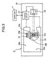
- FIG. 3 is a top plan view schematically showing a servo track write system according to Embodiment 1
- Fig. 4A and Fig. 4B are a top plan view and a side view respectively each showing a state where the disk unit is mounted on the servo track write system shown in Fig. 3.
- the servo track write system shown in Fig. 3 comprises a servo track writer 2 and an upper unit 5 (computing unit).
- the servo track writer 2 mounts components on the board 25 thereof such as a writer-side voice coil motor 26 having a mirror 26a reflecting a laser beam for providing controls over positioning and an actuator for pin pick 26b with a pin pick 24 provided at the tip thereof, a control circuit 27 (recognizing unit, servo data write control unit) for providing controls over the writer-side voice coil motor in the writer side 26 or the like, and a laser displacement gauge 28 for measuring an angle of rotation for the actuator for pin pick 26b by letting the laser beam in the mirror 26a to measure the reflection.
- a writer-side voice coil motor 26 having a mirror 26a reflecting a laser beam for providing controls over positioning and an actuator for pin pick 26b with a pin pick 24 provided at the tip thereof
- a control circuit 27 (recognizing unit, servo data write control unit) for providing controls over the writer-side voice coil motor in the writer side 26 or the
- the control circuit 27 having a microcomputer recognizes a movable range by controlling the head actuator 14 and obtains a pitch angle for each cylinder from the recognized movable range by using the upper unit 5.
- the upper unit 5 is a computing unit such as a computer. This upper unit 5 computes a pitch angle for each cylinder according to data for the movable range of the head actuator 14 transmitted from the control circuit 27, and sends back the computed pitch angle to the control circuit 27.
- the servo track writer 2 inserts, when writing data in a servo track, a pin-pick 24 within the disk unit 1 through an opening section 23 of the base 11 to install the disk unit 1 and have the edge section of the arm 21 for the head actuator 14 supported (Refer to Fig. 4A, Fig. 4B).
- the control circuit 27 controls movement of the head actuator 14 by moving the actuator for pin pick 26b, namely by moving a position of the pin pick 24 with the writer-side voice coil motor 26 according to a result of a laser measured by the laser displacement gauge 28.
- the unit-side voice coil motor 17 is biased from the control circuit 27 so as to slightly press the head actuator 14 in the side of disk unit 1 against the pin pick 24.
- the head actuator 14 for the disk unit 1 moves in the same direction as that of the actuator for pin pick 26b for the servo track writer 2.
- Controls provided by the servo track writer 2 to recognize each stopper space in each disk unit are executed according to this bias control.
- Fig. 5 is a flowchart for explaining an operation for writing data in a servo track according to Embodiment 1
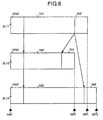
- Fig. 6 is a view for explaining an example of zone layout according to Embodiment 1
- Figs. 7A to 7C are views showing an arrangement of cylinders on the disk in the radial direction thereof according to Embodiment 1
- Fig. 8 is a view for explaining a method of increasing a TPI margin according to Embodiment 1.
- Assembly of the disk unit 1 is completed by assembling components including the disk 12 with disks therein, head actuator 14 and the head 16 in the base 11, and as shown in Fig. 4, the disk unit 1 is positioned on a supporting base 29 of the servo track writer 2 with supporting members 29a, 29b, and 29c.
- the laser displacement gauge 28 is driven, and the writer-side voice coil motor 26 is driven by controlling by the control circuit 27 (step S1).
- a movable range of the head actuator 14 between the stoppers 17a and 17b is obtained. Therefore, the head actuator 14 is moved until it strikes the stoppers 17a, 17b in the outer side and in the inner side respectively.
- the head actuator 14 is swung by the writer-side voice coil motor 26 of the servo track writer 2. At that point of time, the head actuator 14 moves in association with rotation of the actuator for pin pick 26b with a pin pick 24 thereon for supporting the head actuator 14 itself.
- a range of movement of the head actuator 14, namely a range of movement of the actuator for pin pick 26b is measured as an angle from an incident laser beam to the mirror 26a and a reflected beam thereof by the laser displacement gauge 28 (step S2).
- a movable range (a space between the stoppers 17a and 17b) of the head actuator 14 is recognized by checking its each movement to the inner. side as well as to the outer side as an angle specific to the disk unit 1. Then, assuming that the recognized angle is ⁇ and a prespecified number of cylinders is N, the angle ⁇ and the number of cylinders N are transmitted to the upper unit 5 (step S3).
- the pitch angle P is sent back to the control circuit 27.
- the control circuit 27 executes an operation for writing servo data in each specified disk according to the feed pitch angle P (step S5).
- a prespecified number of cylinders is decided by adding essential zones which are the outer guard band and inner guard band (a common size in each disk unit) to data cylinders constituting the data zone.
- Fig. 6 shows zone layouts ZL11, ZL12 and ZL13 of three types of disk 12a, 12b and 12c respectively on which operations for writing servo track are executed respectively each with a different stopper space making a comparison thereamong.
- a relation of the sizes among the zone layouts ZL11, ZL12, and ZL13 each shown in Fig. 6 is as follows: ZL12 (narrowest stopper space) ⁇ ZL11 (intermediate stopper space) ⁇ ZL13 (widest stopper space).
- the operation for writing data in a servo track on a disk requires, as already described, a condition in which a prespecified total number of cylinders is to be written on the disk regardless of any space between the stoppers, but the same number of data tracks is provided on each of the zone layouts ZL1, ZL2, and ZL3 with the same track pitch in the conventional type of writer, while in Embodiment 1, if a fixed-sized outer guard zone OGZ and a fixed-sized inner guard zone IGZ are insured, all space left between the zones OGZ and IGZ is used as a data zone.
- each of the zone layouts ZL11, ZL12, and ZL13 does not have the same sized data zone DZ like in the conventional type thereof, but has each of data zones DZ1, DZ2 and DZ3 respectively as shown in Fig. 6.
- the relation among the sizes of the data zones DZ1, DZ2 and DZ3 shown in Fig. 6 is DZ2 (narrowest space between the stoppers 17a and 17b) ⁇ DZ1 (intermediate space between the stoppers 17a and 17b) ⁇ DZ3 (widest space between the stoppers 17a and 17b), and the difference among the sizes occurs due to a space between the stoppers 17a and 17b.
- a spare zone corresponding to a range outside of the movable range of the head actuator 14 in the inner side exists in a space, in the radial direction of each of the disks 12a, 12b and 12c, from the inner circuit to a cylinder just starting the inner guard zone.
- an inner guard zone IGZ is set to a constant size in each disk, which makes wider any of the data zones DZ1, DZ2 and DZ3 between the outer guard zone OGZ and the inner guard zone IGZ as compared to that of the conventional type thereof.
- the number of cylinders provided in each of the data zones DZ1, DZ2 and DZ3 is common, so that the difference among them is expressed by the feed pitch angle P.
- a disk number is i
- a number of a disk 12a is 1
- a number of a disk 12b is 2
- a number of a disk 12c is 3
- P3 ⁇ 3/N, respectively.
- a relation of ⁇ 2 ⁇ ⁇ 1 ⁇ ⁇ 3 can be obtained from the space between the stoppers 17a and 17b shown in Fig. 6, and for a feed pitch angle, a relation of P2 ⁇ P1 ⁇ P3 can be obtained.
- a track pitch is increasingly widened in the order of the disks 12b, 12a, 12c.
- a wider track pitch can be acquired.
- a disk has the configuration in which an angle is obtained from a space between the stoppers 17a and 17b obtained by moving the head actuator 14, further a feed pitch angle for each cylinder is decided according to a prespecified number of cylinders from the angle, and servo data is written thereon according to the pitch angle. Accordingly, when the space between the stoppers 17a and 17b is more widened, the feed pitch angle becomes larger, with which a larger track pitch for each cylinder can be acquired, so that it is possible to make effective use of a spare region generated according to the stopper without fixing a track pitch.
- the track pitch is set as wide as possible according to the stopper space specific to each disk unit, so that most disk units each having an average stopper space can insure a larger margin (described as TPI (Track Per Inch) margin hereinafter) as compared to that in the conventional technology to prevent destruction of recorded data in adjoining tracks by each of read/write heads mounted on each disk unit, which allows yields at a testing step to be improved and also reliability thereof to be improved.
- TPI Track Per Inch
- the reference numeral 16a indicates a read head for reading data
- the reference numeral 16b indicates a write head for writing data.
- the head 16 comprises those read head 16a and write head 16b.
- a core width of the write head 16b is 3.4 ⁇ m ⁇ 0.3 ⁇ m
- a TPI for each track is 3.9 ⁇ m.
- the conventional type of disk having 6, 000 cylinders can increase the number of cylinders by 300 cylinders according to Embodiment 1, and a constant value DS as a dead space is increased from 0.2 ⁇ m to 0.4 ⁇ m so that the TPI can be increased from 3.9 ⁇ m to 4.1 ⁇ m.
- the TPI margin is increased by a required minimum value, displacement of a write position can be absorbed by the widened dead space even if an extra angle is added to the head 16, namely to the write head 16b, which makes it possible to prevent data from being written in adjoining tracks.
- an angle of the actuator for the disk unit is recognized by using the laser displacement gauge for writing servo data, so that the conventional technology is applicable to the present invention, which allows the need for any particular configuration for recognizing an angle to be eliminated.
- the servo track writer executes, when writing servo data, measurement of a length by reflecting a laser beam emitted from the laser displacement gauge with the mirror of the actuator itself to the laser displacement gauge, and provides controls over positioning of the actuator for the disk unit using a pin pick according to the measured length, so that the need for attaching a mirror to a disk unit having been becoming increasingly smaller in recent years has been eliminated, and with this feature, the movement of an actuator in a disk unit side can more accurately be recognized by the servo track writer with configuration obtained simply by attaching the servo track writer to the disk unit.
- a track pitch is provided as wide as possible within a maximum movable range of the head, so that a TPI margin larger as compared to that in the conventional technology can be acquired, and with this feature, yield at a testing step is improved and reliability thereof is also improved.
- a position of each cylinder is decided according to the track pitch and servo data is recorded in a disk, so that a head can be positioned in each cylinder.
- servo data may duplicatedly be recorded by a specified pitch angle in the radial direction of a disk.
- a TPI margin may be acquired for each track pitch for improvement of reliability.
- each zone of the disk may comprise a different track pitch.
- Embodiment 1 a different track pitch may be applied in each face of the disk.
- cylinders required as guard bands in the inner side as well as in the outer side can be acquired without fail regardless of the total number of cylinders.
- a data zone is obtained by fixing the number of cylinders at a constant value, but like in Embodiment 2 described below, a data zone may be obtained by fixing a track pitch at a contact value.
- the configuration and form of the disk unit is the same as those in Embodiment 1 shown in Fig. 1 and Fig. 2, so that figures and description thereof are omitted herein, and description is made hereinafter only for operations different therefrom.
- Fig. 9 is a flowchart for explaining an operation for writing data in a servo track according to Embodiment 2
- Figs. 10A and 10B are views showing an arrangement of cylinders on a desk in the radial direction thereof according to Embodiment 2. The operations until recognizing a space between the stoppers 17a and 17b are also common to Embodiment 2.
- the control circuit 27 (recognizing unit, servo data write control unit) (step S11).
- the control circuit 27 measures a range of movement of the actuator for pin pick 26b as an angle from an incident laser beam to the mirror 26a as well as the reflection thereof with the laser displacement gauge 28 (step S12).
- the control circuit 27 recognizes, with this measurement, a movable range (a space between the stoppers 17a and 17b) of the head actuator 14 from its each movement to the inner side as well as to the outer side as an angle specific to the disk unit 1 (step S13).
- the angle ⁇ and the pitch angle P are sent from the control unit 27 to the upper unit 5 (computing unit). Therefore, the upper unit 5 obtains the total number of cylinders according to the expression (2). Namely, the upper unit 5 evenly divides the angle ⁇ by the prespecified pitch angle P and computes the total number of cylinders that can be provided according to the above operation (step S14).
- the control circuit 27 subtracts the number of cylinders ON for the outer guard band and the number of cylinders IN for the inner guard band from the total number of cylinders to obtain the number of data cylinders DC for a data zone (step S15).
- an operation for writing servo data in a specific disk is executed according to the prespecified track pitch based on the number of data cylinders DC (step S16).
- a relation of ⁇ 5 > ⁇ 4 can be obtained from the space between the stoppers 17a and 17b shown in Fig. 6, so that, for the number of cylinders, a relation of N5 > N4 can be obtained. Accordingly, the disk 12e has a larger number of tracks than that in the disk 12d according to the relation of the number of cylinders between the data zones DZ 1 and DZ3. In other words, when the spare zone gets narrower, a larger number of tracks can be acquired.
- FIG. 11 is a flowchart for explaining the processing for computing a track pitch according to Embodiment 2.
- a data pattern is written at an arbitrary track position on a disk by one round by using a temporary track pitch (step S21).
- the head actuator 14 is controlled for positioning by the control circuit 27, and an operation for writing data is executed by the head 16. Then, noise patterns are written also by the head 16 in the adjoining tracks to the right as well as to the left from the track in which the data pattern is written (step S22).
- step S22 After the noise patterns are written therein in step S22, the data pattern written in the arbitrary track position is read out by the head 16 (step S23).
- step S24 when the data pattern written in the arbitrary track position is coincident to the data pattern read therefrom so that the data pattern can accurately be read out (step S24), a position of a track in which a noise pattern is written is set to a position further closer to the arbitrary track position in order to narrow the space between the noise pattern and the data pattern (step S25).
- step S22 to step S24 is executed again.
- a position in which a noise pattern is written is, while the data pattern can accurately be read in step S24, gradually got closer to the data pattern in step S25.
- a distance X between a central line of the data pattern and a central line of the noise pattern at that time is computed (step S26). Then a distance between the centers of zones, in which data is written, in the adjoining cylinders, namely a track pitch TP is obtained by adding a required minimum TPI margin to the distance X (step S27).
- Embodiment 2 when the space between the stoppers 17a and 17b is more widened, a larger number of cylinders are provided on the disk, with which the number of cylinders as an object for writing servo data therein can be increased. In this case, it is possible to make effective use of a spare region generated according to the space between stoppers without the necessity of fixing a data zone by fixing the number of cylinders as an object for writing servo data to a constant value.
- the number of data cylinders is discretely set in each disk unit, the number of data cylinders is set as many as possible according to a stopper space in each disk unit, so that most disk units each having an average stopper space therebetween can insure a larger number of data cylinders as compared to that in the conventional method.
- spare data cylinders can be made effective use of by using as a spare region or the like. In this case, as a capacity increases in association with increase of a number of data cylinders, the recording density can be made higher.
- cylinders required as the guard bands in the inner side as well as in the outer side can be acquired without fail regardless of the total number of cylinders.
- a position of each cylinder is decided according to the total number of cylinders and servo data is recorded in a disk, so that a head can be positioned in each cylinder.
- Servo data may duplicatedly be recorded by a specified pitch angle in the radial direction of a disk.
- the number of cylinders required as guard bands in the inner side as well as in the outer side can be acquired without fail regardless the total number of cylinders.
- each face of a disk may have the different total number of cylinders respectively.
- Embodiments 1 and 2 positioning of an actuator for a disk unit is controlled according to movement of an actuator for the servo track writer itself, but like in Embodiment 3 described below, positioning of the actuator for the disk unit may be controlled according to movement of the actuator for the disk unit itself. Description is made hereinafter only for the difference in the configuration as compared to that in the two embodiments described above.
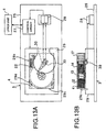
- Fig. 12 is a top plan view schematically showing a servo track write system according to Embodiment 3
- Fig. 13A and Fig. 13B are a top plan view and a side view respectively each showing a state where the disk unit is mounted on the servo track write system shown in Fig. 12.
- the writer-side voice coil motor 26 is mounted on the servo track writer 2, but in Embodiment 3, a system of attaching a mirror to a disk unit is employed in place of employing the pin pick system, so that the voice coil motor is not required for the servo track writer. For this reason, an opening section for a pin pick is not required for a disk unit 4 as well.
- a mirror 30 is attached to the lower section of the head actuator 14.
- the laser displacement gauge 28 for a servo track writer 3 executes measurement with a laser by using this mirror 30.
- the control circuit 27 issues a control signal for positioning of the head actuator 14 only to the unit-side voice coil motor 17 for the disk unit 4 because there is no voice coil motor in the servo track writer 3.
- an object over which the control circuit 27 provides controls is only the unit-side voice coil motor 17 for the disk unit 4, and other operations are the same as those in Embodiments 1 and 2 except that measurement of an angle of a stopper space is obtained from a rotational angle of the head actuator 14 itself.
- the servo track writer 3 executes, when writing servo data, measurement of a length by reflecting a laser beam emitted from the laser displacement gauge 28 with the mirror 30 attached to the head actuator 14 for the disk unit 4 to the laser displacement gauge 28, and provides controls over positioning of the head actuator 14 according to the measured length, so that the movement of the head actuator 14 can be checked by the mirror 30 on the head actuator 14, and with this feature, the movement of the head actuator 14 in the side of disk unit 4 can accurately be recognized by the servo track writer 3.
- a track pitch is provided as wide as possible within a maximum movable range of the head, so that a TPI margin can be acquired more largely than that based on the conventional technology, and with this feature, it is possible to obtain a disk unit in which yield at a testing step is improved and reliability thereof is also improved.
- the disk unit according to the present invention it is possible to obtain a disk unit in which a position of each cylinder is decided according to a track pitch and servo data is recorded in a disk so that a head can be positioned in each cylinder.
- the disk unit according to the present invention it is possible to obtain a disk unit in which servo data can be duplicatedly recorded by a specified pitch angle in the radial direction of a disk.
- the disk unit according to the present invention it is possible to obtain a disk unit in which a TPI margin can be acquired for each track pitch so that reliability thereof is improved.
- each zone of the disk comprise a different track pitch.
- the disk unit according to the present invention it is possible to obtain a disk unit in which a different track pitch is applied in each face of a disk.
- the disk unit according to the present invention it is possible to obtain a disk unit in which, before deciding a track pitch for data cylinders, cylinders required as guard bands in the inner side as well as in the outer side can be acquired without fail regardless of the total number of cylinders.
- the disk unit according to the present invention it is possible to obtain a disk unit in which higher capacity of a disk can be achieved by increasing the total number of cylinders as compared with those based on the conventional technology.
- the disk unit according to the present invention it is possible to obtain a disk unit in which a position of each cylinder is defined by the total number of cylinders and servo data is recorded in a disk so that a head can be positioned in each cylinder.
- the disk unit according to the present invention it is possible to obtain a disk unit in which servo data can duplicatedly be recorded by a specified pitch angle in the radial direction of a disk.
- the disk unit according to the present invention it is possible to obtain a disk unit in which, before deciding the total number of data cylinders, the number of cylinders required as guard bands in the inner side as well as in the outer side can be acquired without fail regardless of the total number of cylinders.
- a feed pitch angle becomes larger in association with a wider space between stoppers, with which a larger track pitch for each cylinder is insured, and with this feature, it can be prevented that a track pitch is fixed, and it is possible to obtain a servo track write system in which a spare region generated according to a stopper space can be made effective use of.
- the number of cylinders provided on the disk is increased in association with a wider space between stoppers, with which the number of cylinders in which servo data is to be written can be increased, so that it is possible to obtain a servo track write system in which a larger capacity of a disk can be achieved.
- the number of cylinders in which servo data is to be written is decided by subtracting the number of cylinders required for providing an outer guard band in the outer side and an inner guard band in the inner side from the total number of cylinders, so that it is possible to obtain a servo track write system in which the cylinders required as the guard bands in the inner side as well as in the outer side can be insured without fail regardless of whether the total number of cylinders is a large number or not.
- an angle of an actuator for the disk unit is recognized to write servo data therein by using a laser displacement gauge, so that existing technology may be applicable to the invention as it is, and it is possible to obtain a servo track write system which does not require any particular configuration for recognition of an angle.
- the movement of an actuator can be checked by a mirror on the actuator, so that it is possible to obtain a servo track write system in which the movement of an actuator in the side of disk unit can more accurately be recognized by the servo track writer.
- the need for attaching a mirror to a disk unit having been becoming increasingly smaller in recent years is eliminated, so that it is possible to obtain a servo track write system in which the movement of an actuator in the side of disk unit can more accurately be recognized by the servo track writer with configuration obtained simply by attaching the servo track writer.
- a feed pitch angle becomes larger in association with a wider space between stoppers, with which a larger track pitch for each cylinder is insured, and with this feature, it can be prevented that a track pitch is fixed, and it is possible to obtain a servo track write method in which a spare region generated according to a stopper space can be made effective use of.
- a required minimum track pitch is obtained so as to enable accurate reading of data, so that it is possible to obtain a servo track write method in which data destruction in a track generated due to a narrow track pitch can be prevented and reliability thereof can be improved.
- the number of cylinders provided on a disk can be increased in association with a wider space between stoppers, with which the number of cylinders in which servo data is to be written can be increased, so that it is possible to obtain a servo track write method in which higher capacity of a disk can be achieved.
Landscapes
- Engineering & Computer Science (AREA)
- Signal Processing (AREA)
- Moving Of The Head To Find And Align With The Track (AREA)
- Signal Processing For Digital Recording And Reproducing (AREA)
Claims (6)
- Servospurschreibsystem für eine Platten-(12)-Einheit, die umfaßt:gekennzeichnet durcheinen Kopf (16) wenigstens zum Lesen von Daten, die in einer Platte (12) gespeichert sind;einen Kopfbetätiger (14) zum Bewegen des Kopfes (16) in einer radialen Richtung der Platte (12); undein Paar von Stoppern (17a, 17b) zum Einschränken der Bewegung des Kopfbetätigers (14) auf einer inneren Seite sowie auf einer äußeren Seite der Platte (12) und auch zum Einschränken eines maximalen Bewegungsbereiches des Kopfes (16); welches Servospurschreibsystem umfaßt:einen Erkennungskopf (5) zum Bewegen des Kopfbetätigers (14), bis er gegen die Stopper (17a, 17b) auf der inneren Seite und auf der äußeren Seite stößt, um einen Bewegungsbereich des Kopfbetätigers (14) zu erkennen;
einen Berechnungskopf (5), der einen Teilungswinkel berechnet, der sich gemäß dem Bewegungsbereich unterscheidet, der durch den Erkennungskopf (5) erkannt wurde; und
einen Servodatenschreibsteuerungskopf (5) zum Steuern einer Operation zum Schreiben von Servodaten auf die Platte (12) gemäß dem Teilungswinkel, der durch den Berechnungskopf (5) erhalten wurde. - Servospurschreibsystem nach Anspruch 1, bei dem der Erkennungskopf (5) einen Winkel des Kopfbetätigers (14) für die Platten-(12)-Einheit unter Verwendung einer Laserversetzungsmeßlehre (28) erkennt.
- Servospurschreibsystem nach Anspruch 1 oder 2, bei dem der Betätiger (14) einen Spiegel (26a) hat, das Servospurschreibsystem die Laserversetzungsmeßlehre (28) hat und der Servodatenschreibsteuerungskopf (5) beim Schreiben von Servodaten eine Messung einer Länge ausführt, indem ein Laserstrahl, der von der Laserversetzungsmeßlehre (28) emittiert wird, mit dem Spiegel (26a) zu der Laserversetzungsmeßlehre (28) reflektiert wird, und Steuerungen für das Positionieren des Kopfbetätigers (14) gemäß einer gemessenen Länge vorsieht.
- Servospurschreibsystem nach Anspruch 1 oder 2, bei dem das Servospurschreibsystem die Laserversetzungsmeßlehre (28), den Spiegel (26a) und einen Betätiger (14) mit einem Stiftpickel hat und die Servodatenschreibsteuerungseinheit (27) beim Schreiben von Servodaten eine Messung einer Länge ausführt, indem ein Laserstrahl, der von der Laserversetzungsmeßlehre (28) emittiert wird, mit dem Spiegel (26a) zu der Laserversetzungsmeßlehre (28) reflektiert wird, und Steuerungen für das Positionieren des Betätigers (14) für die Platteneinheit unter Verwendung des Stiftpickels, der in dem Betätiger (14) des Servospurschreibsystems vorgesehen ist, gemäß der gemessenen Länge vorsieht.
- Servospurschreibverfahren für eine Platteneinheit, die umfaßt:einen Kopf (16) wenigstens zum Lesen von Daten, die in einer Platte (12) gespeichert sind;einen Kopfbetätiger (14) zum Bewegen des Kopfes (16) in einer radialen Richtung der Platte (12); undein Paar von Stoppern (17a, 17b) zum Einschränken der Bewegung des Kopfbetätigers (14) auf einer inneren Seite sowie auf einer äußeren Seite der Platte (12) und auch zum Einschränken eines maximalen Bewegungsbereiches des Kopfes (16); welches Verfahren umfaßt:einen ersten Schritt zum Bewegen des Kopfbetätigers (14), bis er gegen die Stopper (17a, 17b) auf der inneren Seite und auf der äußeren Seite stößt, um einen Bewegungsbereich des Kopfbetätigers (14) zu erkennen;einen zweiten Schritt zum Berechnen eines Teilungswinkels, der sich gemäß dem Bewegungsbereich unterscheidet, der bei dem ersten Schritt erkannt wurde; undeinen dritten Schritt zum Vorsehen von Steuerungen für eine Operation zum Schreiben von Servodaten auf die Platte (12) gemäß dem Teilungswinkel, der bei dem zweiten Schritt erhalten wurde.
- Servospurschreibverfahren nach Anspruch 5, ferner mit:einem vierten Schritt zum Schreiben eines Datenmusters in eine beliebige Spur der Platte (12) bei einer Runde,einem fünften Schritt zum Schreiben von Rauschmustern in benachbarte Spuren auf den rechten und linken Seiten von der beliebigen Spur,einem sechsten Schritt zum Auslesen des Datenmusters, das bei dem vierten Schritt geschrieben wurde, aus der beliebigen Spur,einem siebten Schritt zum allmählichen Bewegen der benachbarten Spuren, in die die Rauschmuster zu schreiben sind, dichter zu einer Spur, die mit dem Datenmuster beschrieben worden ist, immer dann, wenn das Datenmuster, das bei dem sechsten Schritt ausgelesen wird, gelesen wird, und Wiederholen des fünften Schrittes und des sechsten Schrittes undeinem achten Schritt zum Addieren, wenn das bei dem sechsten Schritt ausgelesene Datenmuster nicht gelesen werden kann, eines spezifizierten Wertes zu einem Abstand zwischen einer zentralen Position des Datenmusters und einer zentralen Position des Rauschmusters zu dem Zeitpunkt, wenn das Datenmuster unlesbar wird, um die im voraus spezifizierte Spurteilung gemäß der Summe zu bestimmen.
Applications Claiming Priority (3)
| Application Number | Priority Date | Filing Date | Title |
|---|---|---|---|
| JP221278/97 | 1997-08-18 | ||
| JP22127897 | 1997-08-18 | ||
| JP9221278A JPH1166776A (ja) | 1997-08-18 | 1997-08-18 | ディスク装置、サーボトラックライトシステムおよびそのサーボトラックライト方法 |
Publications (3)
| Publication Number | Publication Date |
|---|---|
| EP0902422A2 EP0902422A2 (de) | 1999-03-17 |
| EP0902422A3 EP0902422A3 (de) | 1999-12-08 |
| EP0902422B1 true EP0902422B1 (de) | 2002-05-02 |
Family
ID=16764283
Family Applications (1)
| Application Number | Title | Priority Date | Filing Date |
|---|---|---|---|
| EP98101859A Expired - Lifetime EP0902422B1 (de) | 1997-08-18 | 1998-02-04 | Schreiben von Servospuren auf einer Platte |
Country Status (6)
| Country | Link |
|---|---|
| US (1) | US6151187A (de) |
| EP (1) | EP0902422B1 (de) |
| JP (1) | JPH1166776A (de) |
| KR (1) | KR100288587B1 (de) |
| CN (1) | CN1180428C (de) |
| DE (1) | DE69805144T2 (de) |
Families Citing this family (7)
| Publication number | Priority date | Publication date | Assignee | Title |
|---|---|---|---|---|
| JP2002237142A (ja) * | 2001-02-09 | 2002-08-23 | Matsushita Electric Ind Co Ltd | 磁気記憶媒体、そのトラックピッチ制御方法、その媒体のための磁気記録装置 |
| JP2002367308A (ja) | 2001-06-06 | 2002-12-20 | Hitachi Ltd | 磁気ディスク装置およびサーボライト方法 |
| KR100413771B1 (ko) * | 2001-09-25 | 2004-01-03 | 삼성전자주식회사 | 서보 정보 기록 방법 |
| JP2004158085A (ja) * | 2002-11-05 | 2004-06-03 | Hitachi Global Storage Technologies Netherlands Bv | サーボ情報の書き込み方法、データ記憶装置、プログラム |
| JP4184190B2 (ja) * | 2003-08-21 | 2008-11-19 | 富士通株式会社 | ヘッド制御方法および記録装置 |
| JP4246708B2 (ja) * | 2005-02-14 | 2009-04-02 | 富士通株式会社 | 記憶媒体書込読込装置 |
| JP2007213685A (ja) | 2006-02-08 | 2007-08-23 | Fujitsu Ltd | ディスク装置、ディスクフォーマット方法およびディスクフォーマット装置 |
Family Cites Families (31)
| Publication number | Priority date | Publication date | Assignee | Title |
|---|---|---|---|---|
| JPS5479014A (en) * | 1977-12-06 | 1979-06-23 | Fujitsu Ltd | Recording method of magnetic discs |
| JPS58147802A (ja) * | 1982-02-26 | 1983-09-02 | Nec Corp | フロツピ・デイスクの情報記録方法 |
| JPS59124069A (ja) * | 1982-12-29 | 1984-07-18 | Seiko Epson Corp | 磁気記録再生装置 |
| US4703371A (en) * | 1985-03-04 | 1987-10-27 | Xebec | Disk drive formatting |
| JPS61280016A (ja) * | 1985-06-04 | 1986-12-10 | Fuji Photo Film Co Ltd | 磁気記録再生装置 |
| JPS61279963A (ja) * | 1985-06-05 | 1986-12-10 | Hitachi Ltd | 割込み制御方式 |
| DE3544079C2 (de) * | 1985-12-13 | 1998-07-30 | Bosch Gmbh Robert | Verfahren zur Verarbeitung von Interrupt-Signalen |
| JPS62188015A (ja) * | 1986-02-14 | 1987-08-17 | Ricoh Co Ltd | 磁気デイスク装置におけるサ−ボパタ−ン記録方法 |
| JPS62298061A (ja) * | 1986-06-16 | 1987-12-25 | Seiko Epson Corp | 磁気デイスク装置 |
| JPH0233781A (ja) * | 1988-07-22 | 1990-02-02 | Fujitsu Ltd | 磁気ディスク装置のサーボ情報記録方法 |
| JP2540064B2 (ja) * | 1988-10-28 | 1996-10-02 | 日立電子エンジニアリング株式会社 | サ―ボ情報書込み用のヘッドアッセンブリ駆動機構 |
| JP2762306B2 (ja) * | 1989-09-28 | 1998-06-04 | 日立電子エンジニアリング株式会社 | ハードディスク・アセンブリの位置決め装着機構 |
| JP2553716B2 (ja) * | 1989-11-02 | 1996-11-13 | 富士通株式会社 | 磁気ディスク装置 |
| JPH03203071A (ja) * | 1989-12-28 | 1991-09-04 | Fujitsu Ltd | 磁気ディスク装置におけるサーボ信号書き込み方法およびサーボディスク媒体 |
| JPH0540725A (ja) * | 1991-08-05 | 1993-02-19 | Shikoku Nippon Denki Software Kk | 入出力制御装置 |
| JPH0589620A (ja) * | 1991-09-30 | 1993-04-09 | Toshiba Corp | 磁気デイスク装置 |
| US6040955A (en) * | 1992-06-11 | 2000-03-21 | International Business Machines Corporation | Self servo writing file |
| JPH065020A (ja) * | 1992-06-17 | 1994-01-14 | Fujitsu Ltd | サーボパターンの書込み装置および書込み方法 |
| JPH06124552A (ja) * | 1992-10-09 | 1994-05-06 | Fujitsu Ltd | 磁気ディスク用stw装置 |
| WO1994011864A1 (en) * | 1992-11-10 | 1994-05-26 | Hardisk Technology | Self-servowriting disk drive and method |
| US6215606B1 (en) * | 1993-03-08 | 2001-04-10 | International Business Machines Corporation | Method and system for determining the widest recording head of a recording device |
| JP2570120B2 (ja) * | 1993-08-02 | 1997-01-08 | 日本電気株式会社 | サーボトラックライタのヘッドキャリッジ機構 |
| US5559648A (en) * | 1993-08-13 | 1996-09-24 | Integral Peripherals, Inc. | Method for optimizing track location during servo writing |
| JP2624164B2 (ja) * | 1994-01-28 | 1997-06-25 | 日本電気株式会社 | サーボトラックライタ |
| JP2635942B2 (ja) * | 1994-02-10 | 1997-07-30 | インターナショナル・ビジネス・マシーンズ・コーポレイション | 直接アクセス記憶装置のサーボ位置決めの方法及び装置 |
| JPH07254245A (ja) * | 1994-03-14 | 1995-10-03 | Fujitsu Ltd | サーボパターンの書込み装置及び書込み方法 |
| TW280906B (de) * | 1994-12-01 | 1996-07-11 | Ibm | |
| SG70001A1 (en) * | 1994-12-02 | 2000-01-25 | Ibm | Radial self-propagation pattern generation for disk file servowriting |
| JPH08263953A (ja) * | 1995-03-22 | 1996-10-11 | Fujitsu Ltd | 磁気ディスク装置及びその組立方法 |
| US5926336A (en) * | 1996-09-13 | 1999-07-20 | Samsung Electronics Co., Ltd. | Method and apparatus for rewriting servo information on a disk in a hard disk assembly |
| US5761007A (en) * | 1997-02-05 | 1998-06-02 | International Business Machines Corporation | Disk drive with multiple actuators on a single axis having different inertia characteristics |
-
1997
- 1997-08-18 JP JP9221278A patent/JPH1166776A/ja active Pending
-
1998
- 1998-01-30 US US09/016,873 patent/US6151187A/en not_active Expired - Fee Related
- 1998-02-04 DE DE69805144T patent/DE69805144T2/de not_active Expired - Fee Related
- 1998-02-04 EP EP98101859A patent/EP0902422B1/de not_active Expired - Lifetime
- 1998-02-06 KR KR1019980003391A patent/KR100288587B1/ko not_active Expired - Fee Related
- 1998-03-09 CN CNB981060595A patent/CN1180428C/zh not_active Expired - Fee Related
Also Published As
| Publication number | Publication date |
|---|---|
| EP0902422A2 (de) | 1999-03-17 |
| JPH1166776A (ja) | 1999-03-09 |
| DE69805144T2 (de) | 2002-08-22 |
| EP0902422A3 (de) | 1999-12-08 |
| KR19990023062A (ko) | 1999-03-25 |
| CN1208927A (zh) | 1999-02-24 |
| DE69805144D1 (de) | 2002-06-06 |
| CN1180428C (zh) | 2004-12-15 |
| US6151187A (en) | 2000-11-21 |
| KR100288587B1 (ko) | 2001-05-02 |
Similar Documents
| Publication | Publication Date | Title |
|---|---|---|
| US7889454B2 (en) | Distributed servo patterns for data storage media | |
| US5999375A (en) | Positioning inner and outer tracks on a recording disc | |
| US6344950B1 (en) | Head disk assembly including ramp having pivoting locational features | |
| KR100833193B1 (ko) | 디스크 보호 장치와 이를 구비한 하드 디스크 드라이브 | |
| US20020060883A1 (en) | Hard disk drive with load/unload capability | |
| US6433950B1 (en) | Disk drive with radially dispersed servo bursts | |
| US4759119A (en) | Method of fabricating a magnetic head assembly | |
| EP0902422B1 (de) | Schreiben von Servospuren auf einer Platte | |
| US5691862A (en) | Recording/reproducing apparatus with an integrated inductive write, magnetoresistive read head | |
| US6078460A (en) | Head positioning control system for use in a disk drive | |
| US5949616A (en) | Suspension having relief against flexure movement interference | |
| US6970325B2 (en) | Magnetic head apparatus, magnetic reproducing method, and magnetic reproducing apparatus in linear tape system | |
| US20070121251A1 (en) | Method of manufacturing head, head, and disk driving device | |
| US7420758B2 (en) | Head system, recording and reproduction system, and magnetic recording method | |
| KR100773739B1 (ko) | 헤드 짐벌 조립체 및 그를 구비한 하드디스크 드라이브 | |
| US5592351A (en) | Low profile enclosure and mechanism for a single channel head 8mm tape drive | |
| US6724576B2 (en) | Magnetic disk apparatus having ramp road structure fixed to stator and method for manufacturing the same | |
| KR100376807B1 (ko) | 자기저항 헤드용 서보 게인 선형화 장치 및 방법 | |
| US6927935B2 (en) | Method and apparatus for head positioning using servo control in a disk drive | |
| US7626811B2 (en) | Low profile disk drive unit | |
| US7379270B2 (en) | Head supporting mechanism | |
| JP2004039235A (ja) | ハードディスクドライブのアクチュエータロッキング装置 | |
| US7142396B2 (en) | System and method for damage prevention by improving the shock resistance of a hard disk actuator arm | |
| KR100508717B1 (ko) | 하드디스크드라이브 용량 가변방법 | |
| US20030128356A1 (en) | Three-dimensional laser beam detection device |
Legal Events
| Date | Code | Title | Description |
|---|---|---|---|
| PUAI | Public reference made under article 153(3) epc to a published international application that has entered the european phase |
Free format text: ORIGINAL CODE: 0009012 |
|
| AK | Designated contracting states |
Kind code of ref document: A2 Designated state(s): DE FR GB |
|
| AX | Request for extension of the european patent |
Free format text: AL;LT;LV;MK;RO;SI |
|
| RIC1 | Information provided on ipc code assigned before grant |
Free format text: 6G 11B 5/55 A, 6G 11B 5/596 B, 6G 11B 21/10 B |
|
| PUAL | Search report despatched |
Free format text: ORIGINAL CODE: 0009013 |
|
| RIC1 | Information provided on ipc code assigned before grant |
Free format text: 6G 11B 5/55 A, 6G 11B 5/58 B, 6G 11B 5/596 B, 6G 11B 21/10 B, 6G 11B 5/02 B |
|
| AK | Designated contracting states |
Kind code of ref document: A3 Designated state(s): AT BE CH DE DK ES FI FR GB GR IE IT LI LU MC NL PT SE |
|
| AX | Request for extension of the european patent |
Free format text: AL;LT;LV;MK;RO;SI |
|
| 17P | Request for examination filed |
Effective date: 20000525 |
|
| AKX | Designation fees paid |
Free format text: DE FR GB |
|
| 17Q | First examination report despatched |
Effective date: 20000724 |
|
| GRAG | Despatch of communication of intention to grant |
Free format text: ORIGINAL CODE: EPIDOS AGRA |
|
| GRAG | Despatch of communication of intention to grant |
Free format text: ORIGINAL CODE: EPIDOS AGRA |
|
| GRAH | Despatch of communication of intention to grant a patent |
Free format text: ORIGINAL CODE: EPIDOS IGRA |
|
| GRAH | Despatch of communication of intention to grant a patent |
Free format text: ORIGINAL CODE: EPIDOS IGRA |
|
| REG | Reference to a national code |
Ref country code: GB Ref legal event code: IF02 |
|
| GRAA | (expected) grant |
Free format text: ORIGINAL CODE: 0009210 |
|
| AK | Designated contracting states |
Kind code of ref document: B1 Designated state(s): DE FR GB |
|
| REF | Corresponds to: |
Ref document number: 69805144 Country of ref document: DE Date of ref document: 20020606 |
|
| ET | Fr: translation filed | ||
| PLBE | No opposition filed within time limit |
Free format text: ORIGINAL CODE: 0009261 |
|
| STAA | Information on the status of an ep patent application or granted ep patent |
Free format text: STATUS: NO OPPOSITION FILED WITHIN TIME LIMIT |
|
| 26N | No opposition filed |
Effective date: 20030204 |
|
| PGFP | Annual fee paid to national office [announced via postgrant information from national office to epo] |
Ref country code: DE Payment date: 20090129 Year of fee payment: 12 |
|
| PGFP | Annual fee paid to national office [announced via postgrant information from national office to epo] |
Ref country code: GB Payment date: 20090204 Year of fee payment: 12 |
|
| PGFP | Annual fee paid to national office [announced via postgrant information from national office to epo] |
Ref country code: FR Payment date: 20090213 Year of fee payment: 12 |
|
| REG | Reference to a national code |
Ref country code: GB Ref legal event code: 732E Free format text: REGISTERED BETWEEN 20091112 AND 20091118 |
|
| REG | Reference to a national code |
Ref country code: FR Ref legal event code: TP |
|
| GBPC | Gb: european patent ceased through non-payment of renewal fee |
Effective date: 20100204 |
|
| REG | Reference to a national code |
Ref country code: FR Ref legal event code: ST Effective date: 20101029 |
|
| PG25 | Lapsed in a contracting state [announced via postgrant information from national office to epo] |
Ref country code: FR Free format text: LAPSE BECAUSE OF NON-PAYMENT OF DUE FEES Effective date: 20100301 |
|
| PG25 | Lapsed in a contracting state [announced via postgrant information from national office to epo] |
Ref country code: DE Free format text: LAPSE BECAUSE OF NON-PAYMENT OF DUE FEES Effective date: 20100901 |
|
| PG25 | Lapsed in a contracting state [announced via postgrant information from national office to epo] |
Ref country code: GB Free format text: LAPSE BECAUSE OF NON-PAYMENT OF DUE FEES Effective date: 20100204 |