EP0899485B1 - Steuereinrichtung für ein stufenloses Getriebe - Google Patents
Steuereinrichtung für ein stufenloses Getriebe Download PDFInfo
- Publication number
- EP0899485B1 EP0899485B1 EP98116026A EP98116026A EP0899485B1 EP 0899485 B1 EP0899485 B1 EP 0899485B1 EP 98116026 A EP98116026 A EP 98116026A EP 98116026 A EP98116026 A EP 98116026A EP 0899485 B1 EP0899485 B1 EP 0899485B1
- Authority
- EP
- European Patent Office
- Prior art keywords
- continuously variable
- gear
- gear ratio
- speed
- vehicle
- Prior art date
- Legal status (The legal status is an assumption and is not a legal conclusion. Google has not performed a legal analysis and makes no representation as to the accuracy of the status listed.)
- Expired - Lifetime
Links
Images


Classifications
-
- F—MECHANICAL ENGINEERING; LIGHTING; HEATING; WEAPONS; BLASTING
- F16—ENGINEERING ELEMENTS AND UNITS; GENERAL MEASURES FOR PRODUCING AND MAINTAINING EFFECTIVE FUNCTIONING OF MACHINES OR INSTALLATIONS; THERMAL INSULATION IN GENERAL
- F16H—GEARING
- F16H61/00—Control functions within control units of change-speed- or reversing-gearings for conveying rotary motion ; Control of exclusively fluid gearing, friction gearing, gearings with endless flexible members or other particular types of gearing
- F16H61/66—Control functions within control units of change-speed- or reversing-gearings for conveying rotary motion ; Control of exclusively fluid gearing, friction gearing, gearings with endless flexible members or other particular types of gearing specially adapted for continuously variable gearings
- F16H61/664—Friction gearings
- F16H61/6648—Friction gearings controlling of shifting being influenced by a signal derived from the engine and the main coupling
-
- F—MECHANICAL ENGINEERING; LIGHTING; HEATING; WEAPONS; BLASTING
- F16—ENGINEERING ELEMENTS AND UNITS; GENERAL MEASURES FOR PRODUCING AND MAINTAINING EFFECTIVE FUNCTIONING OF MACHINES OR INSTALLATIONS; THERMAL INSULATION IN GENERAL
- F16H—GEARING
- F16H37/00—Combinations of mechanical gearings, not provided for in groups F16H1/00 - F16H35/00
- F16H37/02—Combinations of mechanical gearings, not provided for in groups F16H1/00 - F16H35/00 comprising essentially only toothed or friction gearings
- F16H37/06—Combinations of mechanical gearings, not provided for in groups F16H1/00 - F16H35/00 comprising essentially only toothed or friction gearings with a plurality of driving or driven shafts; with arrangements for dividing torque between two or more intermediate shafts
- F16H37/08—Combinations of mechanical gearings, not provided for in groups F16H1/00 - F16H35/00 comprising essentially only toothed or friction gearings with a plurality of driving or driven shafts; with arrangements for dividing torque between two or more intermediate shafts with differential gearing
- F16H37/0833—Combinations of mechanical gearings, not provided for in groups F16H1/00 - F16H35/00 comprising essentially only toothed or friction gearings with a plurality of driving or driven shafts; with arrangements for dividing torque between two or more intermediate shafts with differential gearing with arrangements for dividing torque between two or more intermediate shafts, i.e. with two or more internal power paths
- F16H37/084—Combinations of mechanical gearings, not provided for in groups F16H1/00 - F16H35/00 comprising essentially only toothed or friction gearings with a plurality of driving or driven shafts; with arrangements for dividing torque between two or more intermediate shafts with differential gearing with arrangements for dividing torque between two or more intermediate shafts, i.e. with two or more internal power paths at least one power path being a continuously variable transmission, i.e. CVT
- F16H2037/088—Power-split transmissions with summing differentials, with the input of the CVT connected or connectable to the input shaft
-
- F—MECHANICAL ENGINEERING; LIGHTING; HEATING; WEAPONS; BLASTING
- F16—ENGINEERING ELEMENTS AND UNITS; GENERAL MEASURES FOR PRODUCING AND MAINTAINING EFFECTIVE FUNCTIONING OF MACHINES OR INSTALLATIONS; THERMAL INSULATION IN GENERAL
- F16H—GEARING
- F16H37/00—Combinations of mechanical gearings, not provided for in groups F16H1/00 - F16H35/00
- F16H37/02—Combinations of mechanical gearings, not provided for in groups F16H1/00 - F16H35/00 comprising essentially only toothed or friction gearings
- F16H37/06—Combinations of mechanical gearings, not provided for in groups F16H1/00 - F16H35/00 comprising essentially only toothed or friction gearings with a plurality of driving or driven shafts; with arrangements for dividing torque between two or more intermediate shafts
- F16H37/08—Combinations of mechanical gearings, not provided for in groups F16H1/00 - F16H35/00 comprising essentially only toothed or friction gearings with a plurality of driving or driven shafts; with arrangements for dividing torque between two or more intermediate shafts with differential gearing
- F16H37/0833—Combinations of mechanical gearings, not provided for in groups F16H1/00 - F16H35/00 comprising essentially only toothed or friction gearings with a plurality of driving or driven shafts; with arrangements for dividing torque between two or more intermediate shafts with differential gearing with arrangements for dividing torque between two or more intermediate shafts, i.e. with two or more internal power paths
- F16H37/084—Combinations of mechanical gearings, not provided for in groups F16H1/00 - F16H35/00 comprising essentially only toothed or friction gearings with a plurality of driving or driven shafts; with arrangements for dividing torque between two or more intermediate shafts with differential gearing with arrangements for dividing torque between two or more intermediate shafts, i.e. with two or more internal power paths at least one power path being a continuously variable transmission, i.e. CVT
- F16H37/086—CVT using two coaxial friction members cooperating with at least one intermediate friction member
-
- F—MECHANICAL ENGINEERING; LIGHTING; HEATING; WEAPONS; BLASTING
- F16—ENGINEERING ELEMENTS AND UNITS; GENERAL MEASURES FOR PRODUCING AND MAINTAINING EFFECTIVE FUNCTIONING OF MACHINES OR INSTALLATIONS; THERMAL INSULATION IN GENERAL
- F16H—GEARING
- F16H59/00—Control inputs to control units of change-speed- or reversing-gearings for conveying rotary motion
- F16H59/36—Inputs being a function of speed
- F16H59/38—Inputs being a function of speed of gearing elements
- F16H59/40—Output shaft speed
-
- F—MECHANICAL ENGINEERING; LIGHTING; HEATING; WEAPONS; BLASTING
- F16—ENGINEERING ELEMENTS AND UNITS; GENERAL MEASURES FOR PRODUCING AND MAINTAINING EFFECTIVE FUNCTIONING OF MACHINES OR INSTALLATIONS; THERMAL INSULATION IN GENERAL
- F16H—GEARING
- F16H59/00—Control inputs to control units of change-speed- or reversing-gearings for conveying rotary motion
- F16H59/36—Inputs being a function of speed
- F16H59/38—Inputs being a function of speed of gearing elements
- F16H59/42—Input shaft speed
-
- F—MECHANICAL ENGINEERING; LIGHTING; HEATING; WEAPONS; BLASTING
- F16—ENGINEERING ELEMENTS AND UNITS; GENERAL MEASURES FOR PRODUCING AND MAINTAINING EFFECTIVE FUNCTIONING OF MACHINES OR INSTALLATIONS; THERMAL INSULATION IN GENERAL
- F16H—GEARING
- F16H59/00—Control inputs to control units of change-speed- or reversing-gearings for conveying rotary motion
- F16H59/48—Inputs being a function of acceleration
Definitions
- the invention relates to a control system for a continuously variable transmission, and more particularly, to a control system for a continuously variable transmission of a type having a plurality of power transmission paths selectively used according to vehicle running conditions.
- a geared neutral starting system is employed in the continuously variable transmission regardless of belt type or toroidal type.
- the toroidal continuously variable gear mechanism is mounted on a transmission input shaft connected to the engine, and a planetary gear set is mounted on a secondary shaft disposed in parallel to the input shaft.
- the planetary gear set is comprised of three rotary elements, namely a sun gear, an internal gear and a pinion carrier supporting pinions meshed with the sun gear and the internal gear.
- One of these rotary elements, i.e. the internal gear is used as an transmission output gear. Rotation of engine is imparted to the planetary gear set partly directly through the pinion carrier and partly through the sun gear via the toroidal continuously variable gear mechanism.
- the ratio of rotation between the pinion carrier and the sun gear is varied by controlling the gear ratio of the toroidal continuously variable gear mechanism so as to hold the transmission output element, i.e. the sin gear, remaining stand still, providing a neutral condition.
- the gear ratio of the toroidal continuously variable gear mechanism causes the internal gear as the transmission output element to rotate in a forward direction or in a reverse direction.
- This type of continuously variable transmission permits the vehicle to start forward or back without use of a clutch and/or torque converter, which yields improvement of responsibility and power transmission efficiency of the continuously variable transmission.
- the toroidal continuously variable gear mechanism is controlled to vary its gear ratio so as to gain a resultant transmission gear ratio or to provide a target engine speed which is determined on a control map specifying gear ratio change patterns according to vehicle running conditions including vehicle speeds and throttle positions.
- the gear ratio of the toroidal continuously variable gear mechanism is varied by controlling angles of inclination of the roller with respect to the toroidal surfaces of the input and output disks.
- two power transmission paths are organized such that a first power transmission path transmits engine output power to the drive wheels via a toroidal continuously variable gear mechanism and a planetary gear mechanism to reduce the resultant gear ratio as the toroidal continuously variable gear mechanism increases its gear ratio in forward speed ranges and a second power transmission path transmits engine output power to the drive wheels via the toroidal continuously variable gear mechanism only to reduce its gear ratio as the toroidal continuously variable gear mechanism reduces its gear ratio.
- the roller is inclined in a direction in which the toroidal continuously variable gear mechanism increases its gear ratio (this control of gear ratio is referred to as a low mode gear ratio control) after putting the continuously variable transmission in the first transmission path from the geared neutral position and subsequently in an opposite direction in which the toroidal continuously variable gear mechanism reduces its gear ratio (this control of gear ratio is referred to as a high mode gear ratio control) after putting the continuously variable transmission in the second transmission path.
- the toroidal continuously variable gear mechanism maintains inclinations of the roller within the specified limits of angle, preventing the continuously variable transmission from causing a drop in power transmission efficiency.
- this point is a characteristic point determined based on vehicle speeds and throttle openings and lies on a gear ratio control line set forth for each specific throttle opening.
- this line forms a mode switch line, an inclination angle of the line indicating the same resultant gear ratio described above.
- the continuously variable transmission changes the gear ratio control modes or the power transmission paths from one to another.
- the vehicle enters a slope repeatedly sloping up and down with an accelerator pedal remaining fixedly stepped on, i.e. with an throttle remaining open to a fixed position, the vehicle changes its speed according to the up and down slopes. If the vehicle speed changes repeatedly crossing the switch point, the continuously variable transmission switches the power transmission paths frequently, which always cause hunting of a switch of power transmission paths. Further, since the driver does not changes an accelerator pedal position, the driver feels shocks accompanying switches of the power transmission paths. This problem is common to continuously variable transmissions which selectively uses a plurality of power transmission paths.
- US 4,464,952 discloses a toroidal dual path transmission according to the preamble of claim 1, wherein hysteresis is enabled and the ratio is maintained constant at the synchronous point, so as to avoid the hunting problem.
- GB 1 603 853 discloses a variable ratio transmission, wherein the transmission ratio is controlled according to output shaft torque which is measured by dynamometric means.
- the control system for a continuously variable transmission disposed between an engine and drive wheels which incorporating a toroidal continuously variable gear mechanism continuously varies a gear ratio between an input speed from the engine and an output speed to the drive wheels of a vehicle according to gear ratio control patterns predetermined based on vehicle running conditions including a vehicle speed and engine loading and switches the transmission between a plurality of power transmission paths for transmitting engine output torque to the drive wheels, at least one of the power transmission paths including the toroidal continuously variable gear mechanism, which are selectively built up according to switching characteristics predetermined based on vehicle running conditions.
- the continuously variable transmission control system actuates switching means, such as friction coupling clutches, to selectively switch over the power transmission paths from one to another according to the predetermined switchover characteristics based on vehicle running conditions, and controlling the toroidal continuously variable gear mechanism according to the predetermined gear ratio control pattern selected based on vehicle running conditions.
- switching means such as friction coupling clutches
- the continuously variable transmission control system actuates switching means, such as friction coupling clutches, to selectively switch over the power transmission paths from one to another according to the predetermined switchover characteristics based on vehicle running conditions, and controlling the toroidal continuously variable gear mechanism according to the predetermined gear ratio control pattern selected based on vehicle running conditions.
- Each predetermined gear ratio control pattern being partly divided into two separate sections, one of which is used only during acceleration of the vehicle and another of which is used only during deceleration of the vehicle.
- the continuously variable gear mechanism may be of a toroidal continuously variable gear mechanism which is comprised of an input toroidal disk, an output toroidal disk and a roller disposed between the input and output toroidal disks and capable of inclining relative to the input and output toroidal disks and continuously varies a gear ratio between an input speed to the input toroidal disk from the engine and an output speed to the drive wheels from the output toroidal disk according to inclinations of the roller.
- the separate sections of the gear ratio control pattern are provided for a specified band of vehicle speeds including a specific vehicle speed at which the continuously variable transmission is switched between two different power transmission paths.
- the continuously variable transmission control system switches the continuously variable transmission from gear ratio control according to one section of a gear ratio control pattern to gear ratio control according to another section of the gear ratio control pattern when vehicle running condition turns from acceleration to deceleration or vice versa and maintains a gear ratio at the beginning of the switch of gear ratio control until the switch of gear ratio control is completed.
- the continuously variable transmission may built up simultaneously two power transmission paths, first one of which includes the toroidal continuously variable gear mechanism and another of which is free from the toroidal continuously variable gear mechanism in the neutral position. That is, in the neutral position, the toroidal continuously variable gear mechanism is controlled to provide an output speed through the first power transmission path such as to cancel an output speed through the other power transmission path.
- the continuously variable transmission is controlled to switch between two power transmission paths, one of which includes toroidal continuously variable gear mechanism and another of which is free from the toroidal continuously variable gear mechanism, according to a predetermined control pattern based on vehicle running conditions including at least a vehicle speed
- the toroidal continuously variable gear mechanism is controlled to continuously vary a gear ratio according to predetermined control patterns based on vehicle running conditions including at least a vehicle speed and engine loading.
- the gear ratio control pattern for each specified engine loading or throttle opening is partly divided into two separate sections, one section being used only during acceleration of the vehicle and another section being used only during deceleration of the vehicle.
- the toroidal continuously variable gear mechanism is controlled to vary a gear ratio according to different control patterns predetermined suitably for accelerating condition and decelerating condition, so that there is no hunting of switching the power transmission paths of the continuously variable transmission from one to another which is accompanied by shocks.
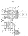
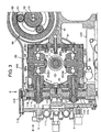
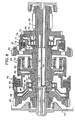
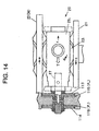
- the continuously variable transmission 10 has three shafts, namely an input shaft 11 connected to an output shaft 2 of an engine 1 through a toroidal damper 3, a hollow primary shaft 12 in which the output shaft 11 is coaxially disposed and a secondary shaft 13 disposed in parallel to the primary shaft 12. These transmission shafts 11-13 extend transversely in the vehicle body.
- the primary shaft 12 mounts thereon a first or rear and a second or front toroidal continuously variable gear mechanism 20 and 30 in order from a side remote from the engine 1 and a loading cam 40.
- the secondary shaft 13 mounts thereon a planetary gear mechanism 50 and two clutches, namely a low mode clutch 60 and a high mode clutch 70. There are low and high mode gear trains 80 and 90 between input shaft 11 and the secondary shaft 13.
- the first and second toroidal continuously variable gear mechanisms 20 and 30 have the same mechanism.
- Each toroidal continuously variable gear mechanism 20, 30 comprises an input disk 21, 31, an output disk 22, 32 and a pair of first and second roller 23, 33 between the input and output surfaces to transmit driving power from one to another.
- the input disks 21 and 31 are mounted on the primary shaft 12 by means of spline-engagement.
- the output disks 22 and 32 are formed integrally as one whole, which is hereafter referred to as an integrated output disk 34.
- First toroidal continuously variable gear mechanism 20 is placed to direct the face of the input disk 21 toward the engine 1, and, however, the second toroidal continuously variable gear mechanism 30 is placed to direct the face of the output disk 32 toward the engine 1.
- the input disks 21 and 31 of the first and second toroidal continuously variable gear mechanisms 20 and 30 are fixedly mounted to opposite ends of the primary shaft 12, respectively, and the output disks 22 and 32 of the first and second toroidal continuously variable gear mechanisms 20 and 30 are mounted for rotation on the primary shaft 12.
- the input shaft 11 is provided with a low mode first gear 81 forming a part of the low mode gear train 80 secured to one end thereof remote from the engine 1 and the loading cam 40 between the low mode first gear 81 and the first toroidal continuously variable gear mechanism 20.
- the integrated output disk 34 is provided with an peripheral first high mode gear 91 forming a part of the high mode gear train 90.
- the secondary shaft 13 mounts thereon for rotation a low mode second gear 82 forming a part of the low mode gear train 80 and a high mode second gear 92 for forming a part of the high mode gear train 90.
- first and second low mode gears 81 and 82 of the low mode gear train 80 are connected through a high mode idle gear 83, and similarly, these high mode first and second gears 91 and 92 of the high mode gear train 90 are connected through a high mode idle gear 93.
- the secondary shaft 13 mounts thereon the planetary gear mechanism 50 having a sun gear 52 meshed with the high mode second gear 92 and an internal gear 53 secured to the secondary shaft 13.
- the high mode clutch 70 is placed adjacent to the high mode second gear 92 to connect the high mode second gear 92 to the secondary shaft 13 and disconnect the high mode second gear 92 from the secondary shaft 13.
- the secondary shaft 13 at one of its end is connected to a differential 5 by means of an output gear train 4 comprising first and second gears 4a and 4b. Driving power is transmitted to right and left wheel drive axles 6a and 6b through the differential 5.
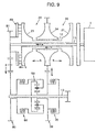
- each roller 22, 23 is supported by a trunnion 25 through a shaft 24 radially extending.
- the roller 22, 23 at its both ends is in contact with the opposite toroidal surfaces of the input and output disks 21 and 22.
- the first and second rollers 22 and 23 are placed in the same plane passing the center axis of rotation of the input shaft 12 and on opposite sides of the center axis of rotation of the input shaft 12.
- the trunnion 25 is held at axially opposite sides by supports 26 so as to rotate about a horizontal axis X tangential to the toroidal surface and perpendicular to the shafts 24 and to move back and forth along the axis X.
- the trunnion 25 is provided with a trunnion rod 27 extending in a direction of the axis X.
- the roller 23 is rolled by means of a speed change control unit 110 secured to the transmission housing 100 through the trunnion 25 and trunnion rod 27.
- the speed change control unit 110 includes a hydraulic control section 111 and a trunnion drive section 112.
- the trunnion drive section 112 includes a piston 113 1 and a piston 114 1 both of which are attached to the rod 27 for the first roller 23 1 and a piston 1132 and a piston 1142 both of which are attached to the rod 27 for the second roller 232.
- Hydraulic pressure chambers 115 1 and 116 1 are formed facing to the first piston 113 1 and the first piston 114 1 , respectively, and similarly, hydraulic pressure chambers 1152 and 1162 are formed facing to the second piston 1132 and the second piston 1142, respectively.
- the hydraulic pressure chamber 115 1 for the first piston 113 1 is placed close to the first roller 23 1 and the hydraulic pressure chamber 116 1 for the first piston 113 1 is placed far from the first roller 23 1 .
- the hydraulic pressure chamber 1162 for the second piston 1132 is placed close to the second roller 232 and the hydraulic pressure chamber 1152 for the second piston 113 2 is placed far from the first roller 23 1 .
- Hydraulic pressure provided by the hydraulic control section 111 is delivered into the hydraulic pressure chambers 115 1 and 1152 through oil paths 117 and 118, respectively, for and into the hydraulic pressure chambers 115 1 and 1162 through oil paths (not shown).
- hydraulic pressure delivery control for the toroidal continuously variable gear mechanism 20 by way of example, when the hydraulic pressure PH in the first and second hydraulic pressure chambers 115 1 and 115 2 becomes higher than a neutral level and relatively to the hydraulic pressure PL in the first and second reduction hydraulic pressure chambers 116 1 and 116 2 , the first trunnion 25 1 is forced to move horizontally toward the right as viewed in Figure 3 and the second trunnion 25 2 is forced toward the left.
- both rollers 23 1 and 23 2 incline so as to shift their contact points with toroidal surfaces of the input disk 21 radially outward and their contact points with toroidal surfaces of the output disk 22 radially inward, thereby lowering a gear ratio of the toroidal continuously variable gear mechanism 20.
- both rollers 23 1 and 23 2 incline so as to shift their contact points with toroidal surfaces of the input disk 21 radially inward and their contact points with toroidal surfaces of the output disk 22 radially outward, thereby changing the toroidal continuously variable gear mechanism 20 to a higher gear ratio.
- Controlling of the hydraulic pressure PH or PL will be described in detail later with reference to a hydraulic control circuit 200 shown in Figure 10.
- the first and second toroidal continuously variable gear mechanisms 20 and 30 always have same input speed and output speed, and provide always the same gear ratio.
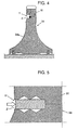
- the integrated output disk 34 is provided with the high mode first ring gear 91 welded to the outer wall of the integrated output disk 34.
- the integrated output disk 34 and the first high mode gear 91 are formed with annular mating shoulders to provide an annular recess Y for welding. That is, a welding portion is separated from one of the toroidal surfaces, namely the toroidal surface 34a, of the integrated output disk 34.
- This annular recess Y prevents the roller 23 from interfering with weld metal padding Z. Welding the high mode first ring gear 91 to the outer wall of the integrated output disk 34 prevents the high mode first ring gear 91 from axially rattling.
- the high mode first ring gear 91 is formed of a low hardness material
- the integrated output disk 34 is made of a high hardness material. Accordingly, while the high mode first ring gear 91 is prevented from breakage of teeth because of tough engagement with the high mode second gear 92 meshed with the sun 52 of the planetary gear mechanism 50, the integrated output disk 34 is prevented from plastic deformation due to frictional contact with the roller 23.
- it is effective to form effective case depth hardened by carburized treatment on them.
- the integrated output disk 34 has a carburized case depth greater than the high mode first ring gear 91.
- the high mode first ring gear 91 may be united with the integrated output disk 34 together by plastic deformation in place of welding.
- each of the high mode first ring gear 91 and the integrated output disk 34 are formed with mating halves of a counter bore Y'.
- a connecting ring Z' made of a soft iron material is press-fitted into the counter bore Y' finished by knurling.
- the connecting ring Z' is plastic deformed to fill flutes of the counter bore Y', as a result of which the high-mode first ring gear 91 and the integrated output disk 34 are united together.
- the integrated output disk 34 may be formed with an external gear as the high mode first ring gear 91 on its periphery.
- a carburized hardening treatment is applied such that the toroidal surface of the integrated output disk 34 has a carburized case depth greater than the external gear.
- FIG. 6 shows the loading cam 40 in detail.
- the loading cam 40 has a cam disk 41 disposed between the low mode first gear 81 of the low mode gear train 80 and the input disk 21 of the first toroidal continuously variable gear mechanism 20.
- the cam disk 41 has a surface cam with alternate arrangement of crests and roots 21a formed thereon.
- the input disk 21 at its back has a surface cam formed thereon correspondingly to the surface cam of the cam disk 41.
- a plurality of rollers 43 held by a retainer disk 42 are interposed between the surface cams.
- the cam disk 41 is mechanically coupled to the low mode first gear 81 by means of a plurality of coupling pins 44.
- conical disk springs 45 As shown in Figure 6, there are arranged conical disk springs 45, a needle bearing 46 and a bearing race 47 between the cam disk 41 and primary shaft flange 12a.
- the cam disk 41 is forced against the input disk 21 by the conical disk springs 45.
- the rollers 43 are interposed between the roots 21a and 41a of the surface cams to transmit drive torque input to the cam disk 41 through the input shaft 11 via the low mode first gear 81 to the input disk 21 of the first toroidal continuously variable gear mechanism 20 and further to the input disk 31 of the second toroidal continuously variable gear mechanism 30 through the primary shaft 12.
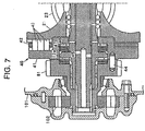
- the transmission rear end cover 101 is provided with an oil pump 102 which is driven by means of the low mode first gear 81.
- the secondary shaft 13 at its opposite ends is supported for rotation by transmission end covers 101 and 103 through bearings 141 and 142, respectively.
- the secondary shaft 13 at its middle portion mounts thereon the high mode second gear 92 and the planetary gear mechanism 50 adjacent to the high mode second gear 92 on one side remote from the engine 1.
- the sun gear 52 of the planetary gear mechanism 50 is meshed with the high mode second gear 92.
- a splined sleeve flange 54 with an external gear is placed on the splined end of the secondary shaft 13 behind the planetary gear mechanism 50 and is meshed with the internal gear 53 of the planetary gear mechanism 50.
- the low mode clutch 60 is mounted for rotation on the secondary shaft 13 behind the sleeve flange 54.
- This low mode clutch 60 comprises an internally splined clutch drum 61 to which the low mode second gear 82 is secured, an externally splined clutch hub 62 disposed radially inside the clutch drum 61 and connected to a flange 55 by means of an externally splined pinion carrier 51, a plurality of splined clutch plates 63 alternately coupled to both clutch drum 61 and clutch hub 62, and a spring loaded piston 64 installed within the clutch drum 61.
- the clutch drum 61 defines a hydraulic chamber 65 therein behind the piston 64.
- the piston 64 is forced axially toward the planetary gear mechanism 50 against a spring 66 by coupling hydraulic pressure applied into the hydraulic pressure chamber 65 by a clutch control unit 120 (see Figure 3), so as to couple the clutch plates 63 all together, thereby bringing the low mode second gear 82 and the pinion carrier 51 into engagement with each other.
- the piston 64 is provided with a balancing piston 67 secured to its front wall to provide a balancing hydraulic chamber 68 therebetween.
- Lubrication oil in the balancing hydraulic pressure chamber 68 cancels thrust force unevenly acting on the piston 64 by means of centrifugal force acting on the oil in the hydraulic pressure chamber 65 to provide uniform distribution of force acting on the piston 64.
- the high mode clutch 70 comprises an internally splined clutch drum 71 which is coupled to a first gear 4a of the output gear train 4 placed on the splined secondary shaft 13 through a parking gear 4d, an externally splined clutch hub 72 disposed radially inside the clutch drum 71 and connected to the high mode second gear 92, a plurality of splined clutch plates 73 alternately coupled to both clutch drum 71 and clutch hub 72, and a spring loaded piston 72 installed within the clutch drum 71.
- the clutch drum 71 defines a hydraulic pressure chamber 75 therein behind the piston 74.
- the piston 74 is forced axially toward the planetary gear mechanism 50 against a spring 76 by coupling hydraulic pressure applied into the hydraulic pressure chamber 75 by the clutch control unit 120, so as to couple the clutch plates 73 all together, thereby bringing the high mode second gear 92 and the first gear 4a of the output gear train 4 placed on the splined secondary shaft 13.
- the piston 74 is provided with a balancing piston 77 secured to its back wall to provide a balancing hydraulic pressure chamber 78 therebetween. Lubrication oil in the balancing hydraulic pressure chamber 78 cancels thrust force unevenly acting on the piston 74 by means of centrifugal force acting on the oil in the hydraulic pressure chamber 75 to provide uniform distribution of force acting on the piston 74.
- the transmission end cover 101 is provided with axial oil paths 131 and 133. Hydraulic oil from the clutch control unit 120 is supplied to the hydraulic pressure chamber 65 of the low mode clutch 60 through the axial oil path 131 and to the hydraulic pressure chamber 75 of the high mode clutch 70 through the axial oil path 133 via an axial oil path 132 formed in the secondary shaft 13.
- the rotation is imparted to the input disk 31 of the second toroidal continuously variable gear mechanism 30 from the input disk 21 of the first toroidal continuously variable gear mechanism 20 through the primary shaft 12 and further transmitted to the integrated output disk 34 through the rollers 23.
- the speed change control unit 110 controls the hydraulic pressure PH for speed increase or the hydraulic pressure PL for speed reduction to hold the rollers 23 of the first and second toroidal continuously variable gear mechanisms 20 and 30 at an inclination angle for a specified gear ratio.
- the rotation imparted to the integrated output disk 34 is further transmitted to the sun gear 52 of the planetary gear mechanism 50 through the high mode gear train 90 comprising the first and second high mode gears 91 and 92.
- the speed change control unit 110 controls the hydraulic pressure PH for speed increase or the hydraulic pressure PL for speed reduction to hold the rollers 23 of the first and second toroidal continuously variable gear mechanisms 20 and 30 at an inclination angle for a given gear ratio.
- the planetary gear mechanism 50 receives the rotation through both pinion carrier 51 and sun gear 52.
- the carrier 51 and the sun gear 52 rotate at a same speed due to the control of gear ratio of the first and second toroidal continuously variable gear mechanisms 20 and 30, not causing rotation of the internal gear 53 of the planetary gear mechanism 50, i.e. rotation transmitted to the differential 5 from the secondary shaft 12 through the output gear ratio 4, at all.
- the continuously variable transmission 10 remains put in a geared neutral state.
- the internal gear 13 rotates in either direction to cause the vehicle to start forward or backward in the low mode control in which the continuously variable transmission 10 is at a high resultant gear ratio.
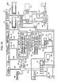
- FIG. 10 shows the hydraulic control circuit 200 comprised of the speed change control unit 110 and the clutch control unit 120 by which the continuously variable transmission 10 is controlled in operation.
- the hydraulic control circuit 200 includes various spool valves, namely a regulator valve 201 for regulating the pressure of a working oil discharged from the oil pump 102 to a specified level of pressure and delivering it into a main pressure line 201, a relief valve 204 for regulating the primary pressure in the main pressure line 201 to a specified level of relief pressure and delivering it into a relief pressure line 203, and a manual shift valve 208 operated by a manual range shift stick (not shown) to bring the main pressure line 201 into communication with first and second primary pressure lines 205 and 206 in a drive (D) range or with first and third primary pressure line 205 and 207 in a reverse (R) range or to disconnect communication of the main pressure line with all of the first to third primary pressure lines 205-207 in a neutral (N) range or a park (P) range.
- the regulator valve 202 and the relief valve 204 are accompanied with linear solenoid valves 209 and 210, respectively.
- Each linear solenoid valve 209, 210 generates a control pressure based on a pressure regulated to a specified level by a reducing valve 211.
- the regulator valve 202 receives the control pressure at its control pressure port 202a to regulate the specified level of line pressure.
- the relief valve 204 receives the control pressure at its control pressure port 204a to regulate the specified level of relief pressure.
- the hydraulic control circuit 200 further includes three spool valves, namely a double-slider forward shift valve (which will be referred to as a forward shift valve for simplicity) 220 for developing a speed increase hydraulic pressure P H according a line pressure and a relief pressure in the drive (D) range, a double-slider reverse shift valve (which will be referred to as a reverse shift valve for simplicity) 230 for developing a speed reduction hydraulic pressure PL in the reverse (R) range, and a shift valve 241 for actuating selectively the shift valves 220 and 230.
- the shift valve 241 shifts its spool between two positions according to whether a pressure is present at the control pressure port 241a.
- the shift valve 241 shifts the spool to the right end position as seen in Figure 10 to bring the main pressure line 201 into communication with a line pressure line 242 leading to the forward shift valve 220 when receiving no line pressure at the control pressure port 241a, or to the left end position to bring the main pressure line 201 into communication with a pressure line 243 leading to the reverse shift valve 230 when receiving the line pressure at the control pressure port 241a.
- the shift valves 220 and 230 are of the same structure.
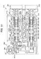
- the forward shift valve 220 has an outer sleeve 222 fitted for axial slide movement into an axial bore 221 (see Figure 11) formed in a valve body 111a of the hydraulic control section 111 of the shift control unit 110 and an inner sleeve 223 fitted for axial slide movement into the outer sleeve 222
- the reverse shift valve 230 has a sleeve 232 fitted for axial slide movement into an axial bore 231 (see Figure 11) formed in a valve body 111a of the hydraulic control section 111 of the shift control unit 110 and an inner sleeve 233 fitted for axial slide movement into the outer sleeve 232.
- the forward shift valve 220 has five ports, namely a line port 224 disposed at the middle in an axial direction and connected to the line pressure line 242, first and second relief ports 225 and 226 disposed at opposite ends and connected to the relief pressure line 203, a speed increase pressure port 227 disposed between the line pressure port 224 and the first relief port 225 and a speed reduction pressure port 228 disposed between the line pressure port 224 and the second relief port 226.
- the reverse shift valve 230 has five ports, namely a line pressure port 234 disposed at the middle in an axial direction and connected to the line pressure line 242, first and second relief ports 235 and 236 disposed at opposite ends and connected to the relief pressure line 203, a speed increase pressure port 237 disposed between the line pressure port 234 and the first relief port 235 and a speed reduction pressure port 238 disposed between the line pressure port 234 and the second relief pressure port 236.
- the valve spool 223 increases an inter-communication opening between the line pressure port 224 and the speed increase pressure port 227, and an inter-communication opening between the second relief port 226 and the speed reduction pressure port 228. Conversely, when the forward shift valve 220 changes the spool position relative to the valve sleeve 222 toward the right from the neutral position, the valve spool 223 increases an inter-communication opening between the line pressure port 224 and the speed reduction pressure port 228, and an inter-communication opening between the first relief port 225 and the speed increase pressure port 227.
- valve spool 233 increases an inter-communication opening between the line pressure port 234 and the speed increase pressure port 237, and an inter-communication opening between the second relief port 236 and the speed reduction pressure port 238, and, conversely, when the reverse shift valve 230 changes the spool position relative to the valve sleeve 232 toward the right from the neutral position, the valve spool 233 increases an inter-communication opening between the line pressure port 234 and the speed reduction pressure port 238, and an inter-communication opening between the first relief port 235 and the speed increase pressure port 237.
- the pressure lines 244 and 245 respectively extending from the speed increase pressure ports 227 and 237 of the forward and reverse shift valve 220 and 230 and the pressure lines 246 and 247 respectively extending from the speed reduction pressure ports 228 and 238 of the forward and reverse shift valve 220 and 230 are connected to the shift valve 241.
- Shift valve 241 places its valve spool to the right end position to bring the pressure lines 244 and 246 extending from the speed increase and reduction pressure ports 227 and 228 of the forward shift valve 220, respectively, into communication with a pressure line 248 leading to the speed increase pressure chambers 115 1 and 115 2 of the trunnion driving section 112 and a pressure line 249 leading to the speed reduction pressure chambers 116 1 and 116 2 of the trunnion driving section 112, respectively.
- the shift valve 241 places its valve spool to the left end position to bring the pressure lines 245 and 247 extending from the speed increase and reduction pressure ports 237 and 238 of the reverse shift valve 230, respectively, into communication with the pressure lines 248 and 249, respectively.
- Figures 11 and 12 show a cam mechanism 260 which moves axially each spool 223, 233 of the forward and reverse shift valves 220 and 230 against a return spring 229, 239 according to axial movement of the valve sleeve 222, 232 caused by a stepping motor 251, 252.
- the stepping motors 251 and 252 are connected to the valve sleeves 222 and 232 through connecting members 253 and 254, respectively.
- the cam mechanism 260 includes a cam 261, a shaft 262, a cam follower lever or slider 263 and drive levers 264 and 265.
- the cam 261 having a cam face 261a is mounted to a trunnion rod 27 of the trunnion 25 of the second toroidal continuously variable gear mechanism 30.
- the shaft 262 is disposed adjacent and perpendicularly to the valve spools 223 and 233 and supported for rotation by the valve body 111a of the hydraulic control section 111.
- the cam follower lever 263 is attached at one of its ends to the shaft and is forced at another end to contact with the cam face 261a of the cam 261.
- the drive lever 264 for forward shift is attached at one of its ends to the shaft 262 and is engaged at another end with an end key slot 223a of the valve spool 223 of the forward shift valve 220.
- the drive lever 265 for reverse shift is attached at one of its ends to the shaft 262 and is engaged at another end with an end key slot 233a of the valve spool 233 of the reverse shift valve 230.
- the axial spool position depends upon the angle of inclination of the rollers 33 of the second toroidal continuously variable gear mechanism 30, and also of the rollers 23 of the toroidal continuously variable gear mechanism 20, i.e. upon the resultant gear ratio of the continuously variable transmission 10.
- the hydraulic pressure control circuit 200 is provided with first and second solenoid valves 271 and 272 for clutch control.
- the first solenoid valve 271 is communicated with the manual shift valve 208 through the first primary pressure line 205.
- the second solenoid valve 272 is communicated with the manual shift valve 208 through the second primary pressure line 206.
- a clutch locking pressure produced by regulating the line pressure from the first primary pressure line 205 is supplied into the hydraulic pressure chamber 65 of the low mode clutch 60 through a clutch pressure line 274 via a fail-safe valve 273 to lock up the low mode clutch 60.
- a clutch locking pressure produced by regulating the line pressure from the second primary pressure line 206 is supplied into the hydraulic pressure chamber 75 of the high mode clutch 70 through a clutch pressure line 275 to lock up the high mode clutch 70.
- the clutch pressure lines 274 and 275 are accompanied with accumulators 276 and 277, respectively, to provide gradual development of the clutch locking pressure in the hydraulic pressure chambers 65 and 75 so as thereby to prevent an occurrence of shift shocks.
- the third primary pressure line 207 extending from the manual shift valve 208 is connected to the control port 241a of the shift valve 241 via the fail-safe valve 273.
- the shift valve 241 receives a line pressure at its control port 241a to place the valve spool to the left end position (reverse position) when the manual shift valve 208 is in the reverse (R) range position.
- the fail-safe valve 273 is accompanied with a solenoid valve 278.
- the solenoid valve 278 provides a control pressure to force the valve spool of the fail-safe valve 273 to the right end position so as thereby to bring the first primary pressure line 205 in communication with the low mode clutch pressure line 274.
- the solenoid valves 271, 272 and 278 are of a three-way type valve which drains a downstream side when both upstream and downstream sides are shut off.
- the hydraulic control circuit 200 is further provided with a lubrication oil line 281 which extends from a drain port of the regulator valve 202 and branches off to a lubrication oil line 282 leading to the first and second toroidal continuously variable gear mechanisms 20 and 30 and a lubrication oil line 283 leading to continuously variable transmission parts other than the toroidal continuously variable gear mechanisms 20 and 30.
- the lubrication oil line 281 is provided with a relief valve 284 to adjust the lubrication oil at a specified level of pressure.
- An upstream part of the lubrication oil line 282 branches off into an oil line 286 provided with a cooler 285 for cooling the lubrication oil and an oil line 287 bypassing the cooler 285.
- the oil line 286 upstream from the cooler 285 is provided with an orifice 288 and a first switch valve 289 disposed in parallel.
- the bypass oil line 287 is provided with a second switch valve 290. Delivery of the lubrication oil to the first and second continuously variable transmission mechanisms 20 and 30 is controlled by means of the first and second switch valves 289 and 290.
- the second switch valve 290 opens to permit the working oil or lubrication oil to flow to the toroidal continuously variable gear mechanisms 20 and 30 bypassing the cooler 285 when the lubrication oil is at a temperature lower than a specified temperature and at a pressure higher than a specified pressure for the purpose of preventing aggravation of flowability of the lubrication oil due to mechanical resistance of the cooler 285 and preventing the cooler 285 from encountering damages and a decrease in durability due to the high pressure lubrication oil.
- the second switch valve 290 closes to make the lubrication oil pass through the cooler before reaching the toroidal continuously variable gear mechanisms 20 and 30.
- the first switch valve 289 opens and closes according to incoming signals from the control unit 300. Specifically, the first switch valve 289 closes when, while the second switch valve 290 remains closed, the engine 1 operates at a speed of rotation lower than a specified speed of rotation and the vehicle runs at a velocity lower than a specified velocity.
- the lubrication oil supplied to the toroidal continuously variable gear mechanisms 20 and 30 through the lubrication oil line 282 is also supplied to bearings supporting the rollers 23 and 33 through an oil line 282a (see Figure 3) and sprayed on the toroidal surfaces through a nozzle 282b (see Figure 3).
- Gear ratio control of the continuously variable transmission 10 depicted in Figure 1 is executed through the control unit 300 shown in block diagram in Figure 16.
- the control unit 300 receives various signals from sensors and switches including at least an engine speed sensor 302, a throttle position or opening sensor 303, a transmission position sensor 304, an oil temperature sensor 305, speed sensors 306 and 307, an idle switch 308, a brake switch 309 and a slope sensor 310.
- the speed sensor 306 attached to the low mode clutch drum 61 detects a speed of input disk 21 of the first toroidal continuously variable gear mechanism 20, and the speed sensor 307 attached to the second gear 92 of the high mode gear train 90 detects a speed of input disk 31 of the first toroidal continuously variable gear mechanism 30.
- the idle switch 308 detects release of the accelerator pedal.
- the brake switch 309 detects stepping on of the brake pedal.
- the slope sensor 310 detects a slope of a road on which the vehicle is traveling. These sensors and switches are well known in various types in the art and may take any known type.
- the control unit 300 provides control signals for various solenoid valves 209, 210, 271, 272, 278, 289 and 290, stepping motors 251 and 252, and other electrically controlled elements in the hydraulic control circuit 200 according to driving conditions represented by signals from the switches and sensors 301-310.
- the hydraulic control circuit 200 shown in Figure 10 is in the drive (D) range in which the manual shift valve 208 takes the drive (D) position to force the shift valve 241 to maintain the valve spool in the right end position (the forward position).
- the toroidal continuously variable gear mechanisms 20 and 30 shown in Figure 3 operate in the same way, the explanation will be given relating to the roller 231 and trunnion 251 of the first toroidal continuously variable gear mechanism 20 by way of example, and the same is true for other rollers and trunnions.
- the solenoid valves 209 and 210 are actuated to generate a specified level of pressure as a line pressure at the control port 202a of the regulator valve 202 and a specified level of pressure as a relief pressure at the control port 204a of the relief valve 204.
- the line pressure is supplied to the inlet pressure port 224 of the forward shift valve 220 through the main pressure line 201 and pressure line 242 via the shift valve 241, and the relief pressure is supplied to the first and second relief ports 225 and 226 of the forward shift valve 220 through the pressure line 203.
- This hydraulic pressure difference control is performed to hold the trunnion 25 and roller 23 in the neutral positions against tractive force (T) exerted on the trunnion 25 or to force them in the axial direction X from the neutral position so as to vary the inclination of the roller for varying the gear ratio of the toroidal continuously variable gear mechanism 20.
- the forward shift valve 220 forces the valve sleeve 222 to shift toward the left as viewed in Figure 11 or to the right as viewed in Figure 10 to decrease the inter-communication openings between the inlet port 224 and the speed increase pressure port 227 and between the second relief port 226 and the speed reduction pressure port 228.
- the cam 261 of the cam mechanism 260 turns through the same angle as the roller 33 in the same direction as indicated by an arrow h in Figure 11, as a result of which the cam follower lever 263, and hence the shaft 262 and the drive lever 264, turns in a direction indicated by an arrow i shown in Figure 12.
- the gear ratio change of the toroidal continuously variable gear mechanism 30 is fixed at the gear ratio.
- the speed change is completed at a point of time that the valve spool 223 reaches the neutral position relative to the valve sleeve 222. Since the neutral position is the position to which the valve sleeve 222 has been shifted by the stepping motor 251 and corresponds to the inclined angle of the roller 23 caused by the cam mechanism 260, the position of the valve sleeve 222 corresponds to the inclined angle of the roller 23, and hence the trunnion 25. This means that the controlled variable of the stepping motor 251 determines the gear ratio of the toroidal continuously variable gear mechanism 20.
- the gear ratio of the toroidal continuously variable gear mechanism 20 is varied according to the number of pulses applied to the stepping motor 251.
- the gear ratio control of the toroidal continuously variable gear mechanism 30 is achieved in the same way when the valve sleeve 222 of the forward shift valve 220 has been shifted in the opposite direction. In this instance, the toroidal continuously variable gear mechanism 20 increases its gear ratio.
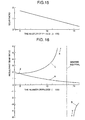
- Figure 15 shows the relationship between the number of pulses for the stepping motor 251, 252 and gear ratio of the toroidal continuously variable gear mechanism 20, 30. As apparent, the gear ratio of the toroidal continuously variable gear mechanism 20, 30 decreases with an increase in the number of pulses.
- Figure 16 shows the relationship between the number of pulses for the stepping motor 251, 252 and resultant gear ratio N of the continuously variable transmission 10 by the control of gear ratio of the toroidal continuously variable gear mechanism 20.
- the continuously variable transmission 10 provides a resultant gear ratio N which differs according to modes of gear ratio control, i.e. according to which mode clutch 60 or 70 has been locked.
- modes of gear ratio control i.e. according to which mode clutch 60 or 70 has been locked.
- the characteristic curve of resultant gear ratio N H of the continuously variable transmission 10 relative to the number of pulses agrees with the characteristic curve of gear ratio of the toroidal continuously variable gear mechanism 20, 30 shown in Figure 15. It is of course that the gear ratios of the toroidal continuously variable gear mechanisms 20 and are different from each other according to the difference in diameter of the first and second gears 91 and 92 of the high mode gear train 90 or the number of teeth between the first and second gears 91 and 92 of the high mode gear train 90.
- the continuously variable transmission 10 provides the reverse mode of gear ratio control in the reverse (R) range where the resultant gear ratio N increases along the characteristic curve R as the number of pulses increases.
- the control unit 300 controls the resultant gear ratio N of the continuously variable transmission 10 based on the characteristic curves according to driving conditions. Specifically, the control unit 300 detects current vehicle speed V and throttle opening ⁇ based on incoming signals from the speed sensor 301 and throttle position sensor 303 to determine a target engine speed of rotation Neo with reference to a gear ratio control map shown in Figure 17. Pulsing control of the first and second stepping motor 251 and 252 and locking and unlocking control of the mode clutches 60 and 70 are performed so that the continuously variable transmission 10 provides a resultant gear ratio N (which is represented by an angle ⁇ in Figure 17) corresponding to the target engine speed of rotation Neo on the basis of the resultant gear ratio control curve L, H or R.
- N which is represented by an angle ⁇ in Figure 17
- the continuously variable transmission 10 has two power transmission paths for transmitting engine output power to the drive wheels in the low mode gear ratio control in which the low mode clutch 60 is locked and the high mode clutch 70 is unlocked, i.e. the power transmission path between the input shaft 11 and the secondary shaft 13 which includes the loading cam 40, the toroidal continuously variable gear mechanisms 20 and 30, the high mode gear train 90 and the planetary gear mechanism 50 and the power transmission path between the input shaft 11 and the secondary shaft 13 which includes the low mode gear train 80 and the planetary gear mechanism 50 only, and single power transmission path in the high mode gear ratio control in which the low mode clutch 60 is unlocked and the high mode clutch 70 is locked, i.e.
- the power transmission path between the input shaft 11 and the secondary shaft 13 which includes the loading cam 40, the toroidal continuously variable gear mechanisms 20 and 30 and the high mode gear train 90. Accordingly, if the engine 1 causes fluctuations of its rotational speed due to changes in compression pressure during one combustion cycle, the fluctuation of rotational speed are transmitted to the secondary shaft 13 through the power transmission path, and then to the drive wheels through the drive axles 6a and 6b, so that the vehicle body generates vibrations.
- the control unit 300 is designed and adapted to perform gear ratio change control of the toroidal continuously variable gear mechanisms 20 and 30 such that the continuously variable transmission 10 transmits engine output power to the drive wheels with an effect of preventing or significantly reducing influence of fluctuations of rotational speed of the engine 1 on the drive wheels.
- the expression (VI) is given by solving the expression (V), taking the second order component given by the third member is 0 (zero).
- Figure 18 is a flow chart illustrating a sequence routine of the fluctuation reducing gear ratio control for a microcoprocessor of the control units 300.
- step S101 a judgement is made as to whether a current engine speed N is equal to or lower than a predetermined threshold value K.
- the flowchart logic orders return to perform another routine. This means that, since fluctuations appearing in the angular velocity of input rotation or the output rotational speed of the engine is not so large when the speed of input rotation N from the engine 1 is relatively high, the gear ratio of the toroidal continuously variable gear mechanism 20, 30 is prevented from being over controlled.
- Po the current central value of the oscillation of gear ratio control pulses
- Pto the current amplitude of the oscillation of gear ratio control pulses given by the expression (VI)
- Wo the current angular velocity of rotation of the engine.
- the number of gear ratio control pulses P(t) is controlled in phase reversely to the oscillation or fluctuation of input rotation from the engine.
- P(t) (P1 + Po)/2 - ⁇ (Pt1 + Pto)/2 ⁇ •sin ⁇ (W1 + Wo)/2 ⁇ •t
- P 1 is the central value of the oscillation of target gear ratio control pulses
- Pti is the amplitude of the oscillation of target gear ratio control pulse given by the expression (VI)
- W 1 is the angular velocity of output rotation of the engine while the target gear ratio control pulses are admitted to the stepping motor.
- the number of gear ratio control pulses P(t) is controlled in phase reversely to fluctuations of output rotation of the engine.
- fluctuations of output rotation from the continuously variable transmission 10 is reduced during slow acceleration.
- the fluctuation reducing gear ratio control may be interrupted to prevent the gear ratio of the toroidal continuously variable gear mechanism 20, 30 from being over controlled. This is because fluctuations appearing in the angular velocity of input rotation or the output rotational speed of the engine is not so large during ordinarily running, i.e. while the speed of input rotation N is lower than the threshold value K, as compared with those during acceleration.
- the toroidal continuously variable gear mechanisms 20 and 30 are controlled so that the continuously variable transmission 10 removes repercussions of the fluctuations of rotational speed of the engine 1 on the drive wheels so as thereby to prevent the vehicle body from causing vibrations during ordinarily running in the drive (D) range, nevertheless, the problem of vibrations of the vehicle body possibly occurs while the continuously variable transmission 10 is put in non-drive range such as the neutral (N) range and the park (P) range where both low and high mode clutches 60 and 70 are unlocked.
- non-drive range such as the neutral (N) range and the park (P) range where both low and high mode clutches 60 and 70 are unlocked.
- control unit 300 is designed and adapted to perform extra gear ratio change control of the toroidal continuously variable gear mechanisms 20 and 30 such that the vehicle body is prevented from generating vibrations due to idling of the engine 1 in the non-drive range (which is hereafter referred to as non-drive range gear ratio control).
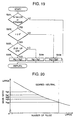
- Figure 19 is a flow chart illustrating a sequence routine of the non-drive range gear ratio control for a microcoprocessor of the control units 300.
- step S201 a judgement is made as to whether the continuously variable transmission 10 is put in the non-drive range, i.e. the neutral (N) range or the park (P) range.
- the flowchart logic orders return to perform another routine.
- step S202 a judgement is further made at step S202 as to whether the temperature of working oil in the continuously variable transmission 10 is equal to or higher than 0°C which is a lower limit on a permissible viscosity of the working oil.
- step S203 When the temperature of working oil in the continuously variable transmission 10 is equal to or higher than 0°C, another judgement is made at step S203 as to whether the engine 1 is put in an idle-up state.
- the term "idle-up state” as used herein shall means and refer to the state in which the engine 1 operates at a speed of rotation higher than an ordinary idle speed of rotation due to engine loading increased by actuation of an engine driven supplementary equipment such as an air-conditioning system while the idle switch 308 is turned on during idling.
- the toroidal continuously variable gear mechanisms 20 and 30 are controlled to provide a first gear ratio Ng1 at step S204.
- the toroidal continuously variable gear mechanisms 20 and 30 are controlled to provide a second gear ratio Ng2 at step S205. Further, when the temperature of working oil is lower than 0°C while the continuously variable transmission 10 is in the non-drive range, the toroidal continuously variable gear mechanisms 20 and 30 are controlled to provide a third gear ratio Ng3 at step S206.
- the continuously variable transmission 10 When starting in the drive (D) range, the continuously variable transmission 10 is controlled such that the toroidal continuously variable gear mechanisms 20 and 30 provides a gear ratio Ngo risen from the neutral gear ratio Ngg at which the geared neutral state is achieved, as shown in Figure 20.
- the continuously variable transmission 10 yields creep force likely an automatic transmission equipped with a torque converter as well as avoiding difficulty in precisely controlling such that the toroidal continuously variable gear mechanisms 20 and 30 provide the specific gear ratio Ngg which is the only gear ratio for achievement of the geared neutral state.
- These first to third gear ratios Nr1, Ng2 and Ng3 become lower in steps from the neutral gear ratio Ngo in this order. That is, in any case, since any gear ratio of the toroidal continuously variable gear mechanisms 20 and 30, i.e.
- Ng1, Ng2 or Ng3 is lower than the gear ratio Ngo at starting in the drive (D) range, or on the higher speed side from the gear ratio Ngo at starting in the drive (D) range, the toroidal continuously variable gear mechanisms 20 and 30 yields high inertia, increasing resistance against rotation of the engine 1 with an effect of lowering fluctuations of rotation of the engine, which restraints vibrations of the vehicle body.
- a change in gear ratio of the toroidal continuously variable gear mechanisms 20 and 30 toward the higher speed side is smaller when the engine 1 is put in the idle-up state in which the engine 1 idles at an increased speed of rotation and causes increased resistance as compared with when the engine 1 is out of the idle-up state, which is desirable for the engine 1 to restrain aggravation of fuel consumption performance.
- the change in gear ratio toward the higher speed side may be increased when the engine 1 is in the idle-up state as compared with when the engine 1 is out of the idle-up state, as a result of which fluctuations of rotation of the engine is more lowered and the vehicle body is more effectively prevented from generating vibrations consequently.
- a change in gear ratio of the toroidal continuously variable gear mechanisms 20 and 30 toward the higher speed side is larger when the working oil is at temperatures as low as it has high viscosity to admit vibrations as compared with when it is at ordinary temperatures, as a result of which fluctuations of rotation of the engine is more lowered and the vehicle body is more effectively prevented from generating vibrations consequently.
- a change in gear ratio of the toroidal continuously variable gear mechanisms 20 and 30 toward the higher speed side may be smaller when the working oil is at low temperatures as compared with when it is at ordinary temperatures so as to prevent the engine 1 from bearing loading in excess.
- the gear ratio of the toroidal continuously variable gear mechanisms 20 and 30 may be periodically varied so as to cancel fluctuations of engine speed likely in the fluctuation reducing gear ratio control executed in the drive range.
- the second gear 92 of the high mode gear train 90 may be provided with a massive disk member 92a such as a flywheel as shown in Figure 21 to generate inertia so as to lower fluctuations of rotation.
- the disk member 92a is desirably formed with circular-arcuate peripheral cuts 92c in diametrically opposite positions.
- the disk member 92a formed with the circular-arcuate peripheral cuts 92c permits the first gear 91 to be installed to the second gear 92 from the front with an effect of providing assembling facility.
- the control unit 300 searches an engine speed most suitable for running conditions dictated by vehicle speed and throttle opening and controls the toroidal continuously variable gear mechanisms 20 and 30 to vary a gear ratio based on the characteristic curves shown in Figure 16. Immediately after starting of the vehicle, the control unit 300 locks the low mode clutch 60 and unlocks the high mode clutch 70 to put the continuously variable transmission 10 in the low mode gear ratio control. When vehicle running conditions change crossing a mode switchover line Z into a high mode zone, the low mode clutch 60 and the high mode clutch 70 are unlocked and locked, respectively, to put the continuously variable transmission 10 in the high mode gear ratio control.
- the control unit 300 alternately locks and unlocks the high and low mode clutches 70 and 60. Since the gear ratio control curves L and H for the drive (D) mode dictate the same resultant gear ratio N when running conditions are on the mode switchover line Z, the continuously variable transmission 10 shifts between the high and low mode gear ratio control without causing felt shift shocks.
- control unit 300 is designed and adapted to perform switchover control of gear ratio control modes which prevents or significantly reduces an occurrence of unpleasant shift shocks.
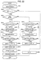
- Figure 22 is a flow chart illustrating a sequence routine of the gear ratio control mode switchover control for a microcoprocessor of the control units 300.
- step S301 When the flow chart logic commences and control proceeds directly to a function block at step S301 where signals from the sensors and switches 301 - 310 are read in. Subsequently, at step S302, an engine speed ESP transmitted to the continuously variable transmission 10 is compared with a switchover engine speed which is obtained by multiplying a current vehicle speed V by a gear ratio c on the mode switchover line Z to judge whether it is under a switchover of control mode.
- the engine speed ESP is approximately equal to the switchover engine speed c ⁇ V, this indicates that an alternation of locking and unlocking is in progress between the low and high mode clutches 60 and 70, then a resultant gear ratio N of the continuously variable transmission 10 is fixed at the gear ratio c on the mode switchover line Z at step S303.
- step S304 a judgement is subsequently made at step S304 as to whether the vehicle running conditions are in the high mode zone.
- a judgement is made at step S305 as to whether the vehicle is under deceleration.
- a judgement is subsequently made at step S310 as to whether the vehicle is acceleration.
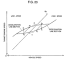
- step S305 When it is determined at step S305 that the vehicle is under deceleration or it is determined at step S310 that the vehicle is not under acceleration, then another judgement is made at step S306 as to whether the result of the judgement made at step S305 in the last cycle of the sequence routine indicates acceleration. When the answer is affirmative, this indicates that the vehicle turns to deceleration for the first time in this cycle, then, the current gear ratio is fixed at step S307 and maintained until it is judged at step S308 that the vehicle speed V has reached a gear ratio control line for deceleration shown in Figure 23.
- Figure 23 shows one of gear ratio control lines for specific throttle opening of the gear ratio control map shown in Figure 17.
- the gear ratio control line includes separate acceleration line section and deceleration line section crossing the mode switchover line Z in a specified band of vehicle speeds.
- the acceleration line section specifies an engine speed on the high side for a specific vehicle speed
- the deceleration line section specifies an engine speed on the low side for the specific vehicle speed.
- the gear ratio control line is changed over from the acceleration line section to the deceleration line section.
- the gear ratio at the beginning of the changing of control line is remained.
- the target engine speed is controlled not to retrace the acceleration line section X toward a point X2 but to jump from the point X3 on the acceleration line section to a point Y2 on the deceleration line section Y at which the gear ratio is identical with that at the point X3 and follow the deceleration line section Y toward a point Y3.
- the switchover between the acceleration and deceleration line sections is not accompanied by a sudden change in gear ratio, so as to prevent or significantly reduce a shock due to a change in gear ratio.
- a target engine speed ESPO is determined according to the current vehicle speed V and throttle opening TVO at step S309.
- step S310 when it is determined at step S310 that the vehicle is under acceleration or it is determined at step S305 that the vehicle is not under deceleration, then another judgement is made at step S311 as to whether the result of the judgement made at step S310 in the last cycle of the sequence routine indicates deceleration.
- the current gear ratio is fixed at step S312 and maintained until it is judged at step S313 that the vehicle speed V has reached the acceleration line section.
- a target engine speed ESPO is determined according to the current vehicle speed V and throttle opening TVO at step S314.
- a speed difference ⁇ ESP of the target engine speed ESPO from the current engine speed ESP is determined at step S315, and a number of drive pulses ⁇ PLS necessary to remove the speed difference ⁇ ESP is subsequently determined at step S316.
- the stepping motor is driven with the drive pulses to attain the target engine speed ESPO.
- the resultant gear ratio is controlled according to the target engine speed changing along the deceleration line section Y.
- the low mode gear ratio control takes place.
- the target engine speed jumps from a point Y3 on the deceleration line section Y to a point X2 on the acceleration line section X.
- the resultant gear ratio is controlled according to the target engine speed changing along the acceleration line section X.
- the gear ratio may be controlled correspondingly to a target engine speed jumping from a point X3 on the acceleration line section X directly to a point Y1 on the deceleration line section Y or from a point Y3 on the deceleration line section Y directly to a point X1 on the acceleration line section X as shown in Figure 23.
- switchover between the gear ratio control line sections is achieved in a short time, it takes a longer time until the target engine speed crosses the mode swichover line Z when it changes from the point Y1 or X1 than when it changes from the point Y2 or X2.
- the acceleration and deceleration line sections of the gear ratio control line are separately provided in a specified band of vehicle speeds in which the mode switchover line exists, the memory of the control unit 300 needs a reduced capacity for the gear ratio control map. If the band of vehicle speeds for the acceleration and deceleration line sections is narrow, the target engine speed changes with a high rate. Accordingly, the band of vehicle speeds is desirably specified in view of the memory capacity.
Landscapes
- Engineering & Computer Science (AREA)
- General Engineering & Computer Science (AREA)
- Mechanical Engineering (AREA)
- Control Of Transmission Device (AREA)
- Transmission Devices (AREA)
- Friction Gearing (AREA)
Claims (5)
- System zur Steuerung eines zwischen einem Motor (1) und Antriebsrädern angeordneten stufenlosen Getriebes (10), das einen stufenlos veränderlichen Zahnradmechanismus (20, 30) zur stufenlosen Veränderung eines Übersetzungsverhältnisses zwischen einer von dem Motor (1) kommenden Eingangsdrehzahl und einer zu den Antriebsrädern gehenden Ausgangsdrehzahl entsprechend den Fahrbedingungen des Fahrzeugs umfaßt und auf wenigstens einem von mehreren Kraftübertragungswegen (a, b), die je nach den Fahrbedingungen des Fahrzeugs wahlweise benutzt werden, die Ausgangsleistung des Motors auf die Antriebsräder überträgt, wobei wenigstens einer der Kraftübertragungswege den stufenlos veränderlichen Zahnradmechanismus (20, 30) umfaßt, wobei das System zur Steuerung des stufenlosen Getriebes folgendes umfaßt: Zustandserfassungseinrichtungen (302, 303) zur Erfassung der Fahrbedingungen des Fahrzeugs einschließlich mindestens Motodrehzahl und Last, Umschalteinrichtungen (60, 70, 271, 272, 273, 278) zum Umschalten der Kraftübertragungswege (a, b) vom einen zum anderen, und eine Steuereinrichtung (300) zur Betätigung der Umschalteinrichtungen (60, 70, 271, 272, 273, 278) zum wahlweisen Umschalten der Kraftübertragungswege (a, b) vom einen zum anderen entsprechend einem in bezug auf die Fahrbedingungen des Fahrzeugs einschließlich mindestens der Fahrzeuggeschwindigkeit vorbestimmten Schaltschema und zum Steuern des stufenlos veränderlichen Zahnradmechanismus (20, 30) nach Schemata zur Steuerung des Übersetzungsverhältnisses, die in bezug auf die Fahrbedingungen des Fahrzeugs einschließlich mindestens Fahrzeuggeschwindigkeit und Motorlast vorbestimmt sind, dadurch gekennzeichnet, daß:jedes Schema zur Steuerung des Übersetzungsverhältnisses zum Teil in zwei getrennte Abschnitte (X, Y) unterteilt ist, wobei einer der beiden Abschnitte (X) nur während der Beschleunigung des Fahrzeugs benutzt wird und der andere der beiden Abschnitte (Y) nur während der Verzögerung des Fahrzeugs benutzt wird.
- System zur Steuerung eines stufenlosen Getriebes nach Anspruch 1, dadurch gekennzeichnet, daß die Steuereinrichtung (300) ein Umschalten der Steuerung des Übersetzungsverhältnisses zwischen den zwei Abschnitten veranlaßt, wenn die Einrichtung (302, 303) zur Erfassung der Fahrbedingungen eine Änderung der Fahrbedingung des Fahrzeugs zwischen Beschleunigung und Verzögerung erfaßt, und ein am Beginn des Umschaltens der Steuerung des Übersetzungsverhältnisses erreichtes Übersetzungsverhältnis des stufenlos veränderlichen Zahnradmechanismus (20, 30) aufrechterhält, bis das Umschalten der Steuerung des Übersetzungsverhältnisses abgeschlossen ist.
- System zur Steuerung eines stufenlosen Getriebes nach Anspruch 1, dadurch gekennzeichnet, daß jedes Steuerschema für das Übersetzungsverhältnis teilweise unterteilt ist in zwei getrennte Abschnitte (X, Y) für einen vorgegebenen Bereich an Fahrzeuggeschwindigkeiten einschließlich einer vorgegebenen Fahrzeuggeschwindigkeit, bei der die Umschalteinrichtung (60, 70, 271, 272, 273, 278) betätigt wird, um die Kraftübertragungswege (a, b) vom einen zum anderen umzuschalten.
- System zur Steuerung eines stufenlosen Getriebes (10) nach einem der vorhergehenden Ansprüche 1 bis 3, dadurch gekennzeichnet, daß wenigstens einer der Kraftübertragungswege (a) den stufenlos veränderlichen Zahnradmechanismus (20, 30) umfaßt und wenigstens ein anderer der Kraftübertragungswege (b) frei ist von dem stufenlos veränderlichen Zahnradmechanismus (20, 30), und daß das stufenlose Getriebe in die Neutralstellung gebracht wird, wenn sowohl der Kraftübertragungsweg (a) als auch der Kraftübertragungsweg (b) benutzt werden.
- System zur Steuerung eines stufenlosen Getriebes (10) nach einem der vorhergehenden Ansprüche 1 bis 4, dadurch gekennzeichnet, daß das stufenlose Getriebe ein ringförmiger stufenlos veränderlicher Zahnradmechanismus (20, 30) ist, der eine ringförmige Eingangsscheibe (21, 31), eine ringförmige Ausgangsscheibe (22, 32) und eine zwischen der ringförmigen Eingangs- und Ausgangsscheibe (21, 22, 31, 32) angeordnete Walze (23, 33) umfaßt.
Applications Claiming Priority (3)
| Application Number | Priority Date | Filing Date | Title |
|---|---|---|---|
| JP24466497A JP3716569B2 (ja) | 1997-08-25 | 1997-08-25 | 無段変速機の制御装置 |
| JP24466497 | 1997-08-25 | ||
| JP244664/97 | 1997-08-25 |
Publications (2)
| Publication Number | Publication Date |
|---|---|
| EP0899485A1 EP0899485A1 (de) | 1999-03-03 |
| EP0899485B1 true EP0899485B1 (de) | 2003-05-14 |
Family
ID=17122125
Family Applications (1)
| Application Number | Title | Priority Date | Filing Date |
|---|---|---|---|
| EP98116026A Expired - Lifetime EP0899485B1 (de) | 1997-08-25 | 1998-08-25 | Steuereinrichtung für ein stufenloses Getriebe |
Country Status (6)
| Country | Link |
|---|---|
| US (1) | US6063002A (de) |
| EP (1) | EP0899485B1 (de) |
| JP (1) | JP3716569B2 (de) |
| KR (1) | KR19990023862A (de) |
| DE (1) | DE69814541T2 (de) |
| ES (1) | ES2200245T3 (de) |
Families Citing this family (37)
| Publication number | Priority date | Publication date | Assignee | Title |
|---|---|---|---|---|
| JP2000120822A (ja) * | 1998-10-21 | 2000-04-28 | Nsk Ltd | 無段変速装置 |
| JP4048625B2 (ja) * | 1998-12-15 | 2008-02-20 | 日産自動車株式会社 | 変速比無限大無段変速機の変速制御装置 |
| JP2000233668A (ja) * | 1999-02-16 | 2000-08-29 | Toyota Motor Corp | 車両の振動抑制装置 |
| JP3508689B2 (ja) * | 1999-07-27 | 2004-03-22 | 日産自動車株式会社 | 変速比無限大無段変速機の制御装置 |
| US6203466B1 (en) | 1999-07-27 | 2001-03-20 | Nsk Ltd. | Continuously variable transmission apparatus |
| US6663532B1 (en) * | 1999-09-20 | 2003-12-16 | Transmisiones Tsp, S. A., De, C.V. | Dual strategy control for a toroidal drive type continuously variable transmission |
| EP1114952B1 (de) | 2000-01-07 | 2003-07-02 | Nissan Motor Co., Ltd. | Stufenloses Getriebe |
| JP3294230B2 (ja) * | 2000-02-22 | 2002-06-24 | 株式会社日立製作所 | 自動車用制御装置,自動車の制御方法,変速機 |
| JP2001271905A (ja) * | 2000-03-27 | 2001-10-05 | Honda Motor Co Ltd | トルクスプリット型無段変速機 |
| DE10033201A1 (de) * | 2000-07-07 | 2002-01-17 | Zf Batavia Llc | Hydraulisches System |
| US6393945B1 (en) * | 2000-09-21 | 2002-05-28 | Caterpillar Inc. | Apparatus and method for preventing hunting between ranges in a continuously variable transmission |
| JP4759887B2 (ja) * | 2001-09-07 | 2011-08-31 | 日産自動車株式会社 | 変速比無限大無段変速機の変速制御装置 |
| JP4867112B2 (ja) * | 2001-09-07 | 2012-02-01 | 日産自動車株式会社 | 変速比無限大無段変速機の変速制御装置 |
| DE10145643C1 (de) * | 2001-09-15 | 2002-11-07 | Case Steyr Landmaschinentechni | Regelung für den Antrieb einer Zapfwelle an einem Landfahrzeug |
| JP3758546B2 (ja) * | 2001-10-05 | 2006-03-22 | 日本精工株式会社 | 無段変速装置 |
| US7493203B2 (en) * | 2002-02-07 | 2009-02-17 | Luk Lamellen Und Kupplungsbau Beteiligungs Kg | Methods for regulating the gear ratio of an automatic power-branched transmission, and automatic power-branched transmission |
| JP3921148B2 (ja) * | 2002-08-07 | 2007-05-30 | ジヤトコ株式会社 | パワースプリット型無段変速装置 |
| DE102004003691B4 (de) * | 2004-01-24 | 2018-10-31 | Zf Friedrichshafen Ag | Kegelringgetriebe |
| DE102004013506A1 (de) * | 2004-03-19 | 2005-10-06 | Daimlerchrysler Ag | Verfahren zum Betrieb eines Antriebsstrangs für ein Kraftfahrzeug |
| US7105937B2 (en) * | 2004-07-14 | 2006-09-12 | Hamilton Sundstrand Corporation | Adjustable variable frequency starter/generator system |
| JP4244944B2 (ja) * | 2005-03-16 | 2009-03-25 | トヨタ自動車株式会社 | 車両用駆動装置の制御装置 |
| EP1953367B1 (de) * | 2007-01-31 | 2019-08-14 | Yamaha Hatsudoki Kabushiki Kaisha | Leerlaufdrehzahlregelung für einen Fahrzeugmotor |
| JP4983498B2 (ja) * | 2007-09-10 | 2012-07-25 | トヨタ自動車株式会社 | 無段変速機の制御装置 |
| JP4488062B2 (ja) | 2007-11-16 | 2010-06-23 | トヨタ自動車株式会社 | 駆動力源回転数制御装置 |
| US8257217B2 (en) * | 2009-02-03 | 2012-09-04 | Ford Global Technologies, Llc | Infinitely variable transmission with offset output shaft |
| AU2011312601B2 (en) * | 2010-10-04 | 2015-08-20 | Allison Transmission Inc. | System for selecting a transmission economy-based shift schedule |
| CN103620266B (zh) * | 2011-04-18 | 2016-08-10 | 传输Cvt股份有限公司 | 设置有辊停放区的无级变速器及防止损坏环形cvt工作区的方法 |
| US9435409B2 (en) * | 2011-11-21 | 2016-09-06 | GM Global Technology Operations LLC | Variator output gearset |
| US9085225B2 (en) * | 2012-01-23 | 2015-07-21 | Dennis Ray Halwes | Infinitely variable transmission |
| JP5612624B2 (ja) * | 2012-03-08 | 2014-10-22 | 富士重工業株式会社 | レンジ切替装置 |
| US8888645B2 (en) * | 2012-07-31 | 2014-11-18 | Gm Global Technology Operations, Llc | Simple planetary gearset continuously variable transmission |
| GB201214316D0 (en) * | 2012-08-10 | 2012-09-26 | Torotrak Dev Ltd | Infinitely-variable transmission for a vehicle |
| JP5741553B2 (ja) * | 2012-11-02 | 2015-07-01 | トヨタ自動車株式会社 | 車両の制御装置 |
| JP6275849B2 (ja) * | 2014-07-23 | 2018-02-07 | アイシン・エィ・ダブリュ株式会社 | 自動変速機の油圧制御装置 |
| US9651127B2 (en) * | 2014-10-17 | 2017-05-16 | Allison Transmission, Inc. | Split power infinitely variable transmission architecture incorporating a planetary type ball variator with low part count |
| JP6474917B2 (ja) | 2015-12-09 | 2019-02-27 | アイシン・エィ・ダブリュ株式会社 | 自動変速機の油圧制御装置 |
| JP6561979B2 (ja) * | 2016-12-24 | 2019-08-21 | トヨタ自動車株式会社 | 車両用駆動装置の制御装置 |
Family Cites Families (9)
| Publication number | Priority date | Publication date | Assignee | Title |
|---|---|---|---|---|
| GB1603853A (en) * | 1978-05-08 | 1981-12-02 | British Leyland Cars Ltd | Variableratio transmissions |
| DE3169011D1 (en) * | 1980-05-31 | 1985-03-28 | Bl Tech Ltd | Control systems for continuously variable ratio transmissions |
| JPS63130442A (ja) * | 1986-11-18 | 1988-06-02 | Nissan Motor Co Ltd | 無段変速機の変速制御装置 |
| JP2748511B2 (ja) * | 1989-03-08 | 1998-05-06 | 日産自動車株式会社 | 変速機の制御装置 |
| JP2847779B2 (ja) * | 1989-07-24 | 1999-01-20 | 日産自動車株式会社 | 無段変速機 |
| JPH03223555A (ja) * | 1990-01-26 | 1991-10-02 | Nippon Seiko Kk | トロイダル型無段変速機 |
| US5213011A (en) * | 1991-04-05 | 1993-05-25 | Mazda Motor Corporation | Power transmission device for vehicle |
| JPH05126239A (ja) * | 1991-06-29 | 1993-05-21 | Mazda Motor Corp | 車両用無段変速機の変速制御装置 |
| JP3185400B2 (ja) * | 1992-09-18 | 2001-07-09 | 日産自動車株式会社 | 変速比無限大無段変速機の変速制御装置 |
-
1997
- 1997-08-25 JP JP24466497A patent/JP3716569B2/ja not_active Expired - Fee Related
-
1998
- 1998-08-25 KR KR1019980034509A patent/KR19990023862A/ko not_active Withdrawn
- 1998-08-25 US US09/139,667 patent/US6063002A/en not_active Expired - Fee Related
- 1998-08-25 ES ES98116026T patent/ES2200245T3/es not_active Expired - Lifetime
- 1998-08-25 EP EP98116026A patent/EP0899485B1/de not_active Expired - Lifetime
- 1998-08-25 DE DE69814541T patent/DE69814541T2/de not_active Expired - Fee Related
Also Published As
| Publication number | Publication date |
|---|---|
| EP0899485A1 (de) | 1999-03-03 |
| ES2200245T3 (es) | 2004-03-01 |
| JPH1163203A (ja) | 1999-03-05 |
| DE69814541D1 (de) | 2003-06-18 |
| KR19990023862A (ko) | 1999-03-25 |
| US6063002A (en) | 2000-05-16 |
| DE69814541T2 (de) | 2003-12-18 |
| JP3716569B2 (ja) | 2005-11-16 |
Similar Documents
| Publication | Publication Date | Title |
|---|---|---|
| EP0899485B1 (de) | Steuereinrichtung für ein stufenloses Getriebe | |
| EP0866242B1 (de) | Steuerungssystem für ein stufenloses Toroidgetriebe | |
| US6030311A (en) | Control system for a continuously variable transmission | |
| EP0905413B1 (de) | Stufenloses toroidgetriebe | |
| US6875152B2 (en) | Vehicle drive line controller | |
| CN102356254B (zh) | 动力传递装置 | |
| US20020028722A1 (en) | Control of infinitely variable transmission | |
| JPH0372866B2 (de) | ||
| JPH08261303A (ja) | 無段変速機 | |
| JPS60255535A (ja) | 無段変速機付車輛の加速制御システム及び方法 | |
| JP3716568B2 (ja) | トロイダル式無段変速機 | |
| EP1099884A2 (de) | Steuereinrichtung eines stufenlosen Toroidgetriebes | |
| JP4329210B2 (ja) | 無段変速機の変速制御装置 | |
| JP3713917B2 (ja) | 無段変速機の制御装置 | |
| JPH1163184A (ja) | 無段変速機の制御装置 | |
| JP3157267B2 (ja) | 車両の動力伝達装置 | |
| JP3279224B2 (ja) | 変速機の制御装置 | |
| JP2000179674A (ja) | パワートレインの制御装置 | |
| JP2000179669A (ja) | パワートレインの制御装置 | |
| EP0969229A2 (de) | Stufenloses Getriebe | |
| JPH042813B2 (de) | ||
| JP4517451B2 (ja) | 無段変速機の制御装置 | |
| JP2848179B2 (ja) | 車両用自動変速機の油圧制御装置 | |
| JP2000179673A (ja) | パワートレインの制御装置 | |
| KR19990054542A (ko) | 비례압력해제밸브를 이용한 벨트식 무단변속기의 유압제어장치 |
Legal Events
| Date | Code | Title | Description |
|---|---|---|---|
| PUAI | Public reference made under article 153(3) epc to a published international application that has entered the european phase |
Free format text: ORIGINAL CODE: 0009012 |
|
| AK | Designated contracting states |
Kind code of ref document: A1 Designated state(s): AT BE CH CY DE DK ES FI FR GB GR IE IT LI LU MC NL PT SE |
|
| AX | Request for extension of the european patent |
Free format text: AL;LT;LV;MK;RO;SI |
|
| 17P | Request for examination filed |
Effective date: 19990903 |
|
| AKX | Designation fees paid | ||
| 17Q | First examination report despatched |
Effective date: 20010214 |
|
| REG | Reference to a national code |
Ref country code: DE Ref legal event code: 8566 |
|
| GRAG | Despatch of communication of intention to grant |
Free format text: ORIGINAL CODE: EPIDOS AGRA |
|
| GRAG | Despatch of communication of intention to grant |
Free format text: ORIGINAL CODE: EPIDOS AGRA |
|
| GRAH | Despatch of communication of intention to grant a patent |
Free format text: ORIGINAL CODE: EPIDOS IGRA |
|
| GRAH | Despatch of communication of intention to grant a patent |
Free format text: ORIGINAL CODE: EPIDOS IGRA |
|
| GRAA | (expected) grant |
Free format text: ORIGINAL CODE: 0009210 |
|
| AK | Designated contracting states |
Designated state(s): DE ES FR GB IT |
|
| RBV | Designated contracting states (corrected) |
Designated state(s): DE ES FR GB IT |
|
| REG | Reference to a national code |
Ref country code: GB Ref legal event code: FG4D |
|
| REF | Corresponds to: |
Ref document number: 69814541 Country of ref document: DE Date of ref document: 20030618 Kind code of ref document: P |
|
| PGFP | Annual fee paid to national office [announced via postgrant information from national office to epo] |
Ref country code: GB Payment date: 20030730 Year of fee payment: 6 |
|
| PGFP | Annual fee paid to national office [announced via postgrant information from national office to epo] |
Ref country code: ES Payment date: 20030806 Year of fee payment: 6 |
|
| PGFP | Annual fee paid to national office [announced via postgrant information from national office to epo] |
Ref country code: FR Payment date: 20030814 Year of fee payment: 6 |
|
| REG | Reference to a national code |
Ref country code: ES Ref legal event code: FG2A Ref document number: 2200245 Country of ref document: ES Kind code of ref document: T3 |
|
| ET | Fr: translation filed | ||
| PLBE | No opposition filed within time limit |
Free format text: ORIGINAL CODE: 0009261 |
|
| STAA | Information on the status of an ep patent application or granted ep patent |
Free format text: STATUS: NO OPPOSITION FILED WITHIN TIME LIMIT |
|
| 26N | No opposition filed |
Effective date: 20040217 |
|
| PG25 | Lapsed in a contracting state [announced via postgrant information from national office to epo] |
Ref country code: GB Free format text: LAPSE BECAUSE OF NON-PAYMENT OF DUE FEES Effective date: 20040825 |
|
| PG25 | Lapsed in a contracting state [announced via postgrant information from national office to epo] |
Ref country code: ES Free format text: LAPSE BECAUSE OF NON-PAYMENT OF DUE FEES Effective date: 20040826 |
|
| GBPC | Gb: european patent ceased through non-payment of renewal fee |
Effective date: 20040825 |
|
| PG25 | Lapsed in a contracting state [announced via postgrant information from national office to epo] |
Ref country code: FR Free format text: LAPSE BECAUSE OF NON-PAYMENT OF DUE FEES Effective date: 20050429 |
|
| REG | Reference to a national code |
Ref country code: FR Ref legal event code: ST |
|
| PG25 | Lapsed in a contracting state [announced via postgrant information from national office to epo] |
Ref country code: IT Free format text: LAPSE BECAUSE OF NON-PAYMENT OF DUE FEES Effective date: 20050825 |
|
| REG | Reference to a national code |
Ref country code: ES Ref legal event code: FD2A Effective date: 20040826 |
|
| PGFP | Annual fee paid to national office [announced via postgrant information from national office to epo] |
Ref country code: DE Payment date: 20060817 Year of fee payment: 9 |
|
| PG25 | Lapsed in a contracting state [announced via postgrant information from national office to epo] |
Ref country code: DE Free format text: LAPSE BECAUSE OF NON-PAYMENT OF DUE FEES Effective date: 20080301 |