EP0899485A1 - Steuereinrichtung für ein stufenloses Getriebe - Google Patents
Steuereinrichtung für ein stufenloses Getriebe Download PDFInfo
- Publication number
- EP0899485A1 EP0899485A1 EP98116026A EP98116026A EP0899485A1 EP 0899485 A1 EP0899485 A1 EP 0899485A1 EP 98116026 A EP98116026 A EP 98116026A EP 98116026 A EP98116026 A EP 98116026A EP 0899485 A1 EP0899485 A1 EP 0899485A1
- Authority
- EP
- European Patent Office
- Prior art keywords
- continuously variable
- engine
- speed
- vehicle
- gear ratio
- Prior art date
- Legal status (The legal status is an assumption and is not a legal conclusion. Google has not performed a legal analysis and makes no representation as to the accuracy of the status listed.)
- Granted
Links
- 230000005540 biological transmission Effects 0.000 title claims abstract description 194
- 230000001133 acceleration Effects 0.000 claims abstract description 50
- 238000011068 loading method Methods 0.000 claims abstract description 30
- 230000007246 mechanism Effects 0.000 claims description 183
- 230000007935 neutral effect Effects 0.000 claims description 32
- 230000008878 coupling Effects 0.000 claims description 10
- 238000010168 coupling process Methods 0.000 claims description 10
- 238000005859 coupling reaction Methods 0.000 claims description 10
- 239000003921 oil Substances 0.000 description 48
- 230000008859 change Effects 0.000 description 24
- 230000002441 reversible effect Effects 0.000 description 23
- 230000009467 reduction Effects 0.000 description 21
- 238000005461 lubrication Methods 0.000 description 19
- 230000035939 shock Effects 0.000 description 12
- 230000010355 oscillation Effects 0.000 description 10
- 238000010586 diagram Methods 0.000 description 8
- 230000001276 controlling effect Effects 0.000 description 6
- 230000007423 decrease Effects 0.000 description 5
- 230000001105 regulatory effect Effects 0.000 description 5
- 230000002829 reductive effect Effects 0.000 description 4
- 238000003466 welding Methods 0.000 description 4
- 230000000694 effects Effects 0.000 description 3
- 230000006870 function Effects 0.000 description 3
- 238000009434 installation Methods 0.000 description 3
- 239000000463 material Substances 0.000 description 3
- 230000002093 peripheral effect Effects 0.000 description 3
- 238000011144 upstream manufacturing Methods 0.000 description 3
- XEEYBQQBJWHFJM-UHFFFAOYSA-N Iron Chemical compound [Fe] XEEYBQQBJWHFJM-UHFFFAOYSA-N 0.000 description 2
- 238000006243 chemical reaction Methods 0.000 description 2
- 230000000875 corresponding effect Effects 0.000 description 2
- 230000013011 mating Effects 0.000 description 2
- 239000002184 metal Substances 0.000 description 2
- 229910052751 metal Inorganic materials 0.000 description 2
- 230000036961 partial effect Effects 0.000 description 2
- 238000009827 uniform distribution Methods 0.000 description 2
- 238000004378 air conditioning Methods 0.000 description 1
- 230000001174 ascending effect Effects 0.000 description 1
- 238000002485 combustion reaction Methods 0.000 description 1
- 230000006835 compression Effects 0.000 description 1
- 238000007906 compression Methods 0.000 description 1
- 238000001816 cooling Methods 0.000 description 1
- 230000002596 correlated effect Effects 0.000 description 1
- 230000003247 decreasing effect Effects 0.000 description 1
- 239000000446 fuel Substances 0.000 description 1
- 239000010720 hydraulic oil Substances 0.000 description 1
- 230000006872 improvement Effects 0.000 description 1
- 230000002452 interceptive effect Effects 0.000 description 1
- 229910052742 iron Inorganic materials 0.000 description 1
- 230000009191 jumping Effects 0.000 description 1
- 230000002035 prolonged effect Effects 0.000 description 1
- 238000010992 reflux Methods 0.000 description 1
- 230000004044 response Effects 0.000 description 1
- 230000004043 responsiveness Effects 0.000 description 1
Images


Classifications
-
- F—MECHANICAL ENGINEERING; LIGHTING; HEATING; WEAPONS; BLASTING
- F16—ENGINEERING ELEMENTS AND UNITS; GENERAL MEASURES FOR PRODUCING AND MAINTAINING EFFECTIVE FUNCTIONING OF MACHINES OR INSTALLATIONS; THERMAL INSULATION IN GENERAL
- F16H—GEARING
- F16H61/00—Control functions within control units of change-speed- or reversing-gearings for conveying rotary motion ; Control of exclusively fluid gearing, friction gearing, gearings with endless flexible members or other particular types of gearing
- F16H61/66—Control functions within control units of change-speed- or reversing-gearings for conveying rotary motion ; Control of exclusively fluid gearing, friction gearing, gearings with endless flexible members or other particular types of gearing specially adapted for continuously variable gearings
- F16H61/664—Friction gearings
- F16H61/6648—Friction gearings controlling of shifting being influenced by a signal derived from the engine and the main coupling
-
- F—MECHANICAL ENGINEERING; LIGHTING; HEATING; WEAPONS; BLASTING
- F16—ENGINEERING ELEMENTS AND UNITS; GENERAL MEASURES FOR PRODUCING AND MAINTAINING EFFECTIVE FUNCTIONING OF MACHINES OR INSTALLATIONS; THERMAL INSULATION IN GENERAL
- F16H—GEARING
- F16H37/00—Combinations of mechanical gearings, not provided for in groups F16H1/00 - F16H35/00
- F16H37/02—Combinations of mechanical gearings, not provided for in groups F16H1/00 - F16H35/00 comprising essentially only toothed or friction gearings
- F16H37/06—Combinations of mechanical gearings, not provided for in groups F16H1/00 - F16H35/00 comprising essentially only toothed or friction gearings with a plurality of driving or driven shafts; with arrangements for dividing torque between two or more intermediate shafts
- F16H37/08—Combinations of mechanical gearings, not provided for in groups F16H1/00 - F16H35/00 comprising essentially only toothed or friction gearings with a plurality of driving or driven shafts; with arrangements for dividing torque between two or more intermediate shafts with differential gearing
- F16H37/0833—Combinations of mechanical gearings, not provided for in groups F16H1/00 - F16H35/00 comprising essentially only toothed or friction gearings with a plurality of driving or driven shafts; with arrangements for dividing torque between two or more intermediate shafts with differential gearing with arrangements for dividing torque between two or more intermediate shafts, i.e. with two or more internal power paths
- F16H37/084—Combinations of mechanical gearings, not provided for in groups F16H1/00 - F16H35/00 comprising essentially only toothed or friction gearings with a plurality of driving or driven shafts; with arrangements for dividing torque between two or more intermediate shafts with differential gearing with arrangements for dividing torque between two or more intermediate shafts, i.e. with two or more internal power paths at least one power path being a continuously variable transmission, i.e. CVT
- F16H2037/088—Power-split transmissions with summing differentials, with the input of the CVT connected or connectable to the input shaft
-
- F—MECHANICAL ENGINEERING; LIGHTING; HEATING; WEAPONS; BLASTING
- F16—ENGINEERING ELEMENTS AND UNITS; GENERAL MEASURES FOR PRODUCING AND MAINTAINING EFFECTIVE FUNCTIONING OF MACHINES OR INSTALLATIONS; THERMAL INSULATION IN GENERAL
- F16H—GEARING
- F16H37/00—Combinations of mechanical gearings, not provided for in groups F16H1/00 - F16H35/00
- F16H37/02—Combinations of mechanical gearings, not provided for in groups F16H1/00 - F16H35/00 comprising essentially only toothed or friction gearings
- F16H37/06—Combinations of mechanical gearings, not provided for in groups F16H1/00 - F16H35/00 comprising essentially only toothed or friction gearings with a plurality of driving or driven shafts; with arrangements for dividing torque between two or more intermediate shafts
- F16H37/08—Combinations of mechanical gearings, not provided for in groups F16H1/00 - F16H35/00 comprising essentially only toothed or friction gearings with a plurality of driving or driven shafts; with arrangements for dividing torque between two or more intermediate shafts with differential gearing
- F16H37/0833—Combinations of mechanical gearings, not provided for in groups F16H1/00 - F16H35/00 comprising essentially only toothed or friction gearings with a plurality of driving or driven shafts; with arrangements for dividing torque between two or more intermediate shafts with differential gearing with arrangements for dividing torque between two or more intermediate shafts, i.e. with two or more internal power paths
- F16H37/084—Combinations of mechanical gearings, not provided for in groups F16H1/00 - F16H35/00 comprising essentially only toothed or friction gearings with a plurality of driving or driven shafts; with arrangements for dividing torque between two or more intermediate shafts with differential gearing with arrangements for dividing torque between two or more intermediate shafts, i.e. with two or more internal power paths at least one power path being a continuously variable transmission, i.e. CVT
- F16H37/086—CVT using two coaxial friction members cooperating with at least one intermediate friction member
-
- F—MECHANICAL ENGINEERING; LIGHTING; HEATING; WEAPONS; BLASTING
- F16—ENGINEERING ELEMENTS AND UNITS; GENERAL MEASURES FOR PRODUCING AND MAINTAINING EFFECTIVE FUNCTIONING OF MACHINES OR INSTALLATIONS; THERMAL INSULATION IN GENERAL
- F16H—GEARING
- F16H59/00—Control inputs to control units of change-speed- or reversing-gearings for conveying rotary motion
- F16H59/36—Inputs being a function of speed
- F16H59/38—Inputs being a function of speed of gearing elements
- F16H59/40—Output shaft speed
-
- F—MECHANICAL ENGINEERING; LIGHTING; HEATING; WEAPONS; BLASTING
- F16—ENGINEERING ELEMENTS AND UNITS; GENERAL MEASURES FOR PRODUCING AND MAINTAINING EFFECTIVE FUNCTIONING OF MACHINES OR INSTALLATIONS; THERMAL INSULATION IN GENERAL
- F16H—GEARING
- F16H59/00—Control inputs to control units of change-speed- or reversing-gearings for conveying rotary motion
- F16H59/36—Inputs being a function of speed
- F16H59/38—Inputs being a function of speed of gearing elements
- F16H59/42—Input shaft speed
-
- F—MECHANICAL ENGINEERING; LIGHTING; HEATING; WEAPONS; BLASTING
- F16—ENGINEERING ELEMENTS AND UNITS; GENERAL MEASURES FOR PRODUCING AND MAINTAINING EFFECTIVE FUNCTIONING OF MACHINES OR INSTALLATIONS; THERMAL INSULATION IN GENERAL
- F16H—GEARING
- F16H59/00—Control inputs to control units of change-speed- or reversing-gearings for conveying rotary motion
- F16H59/48—Inputs being a function of acceleration
Definitions
- the invention relates to a control system for a continuously variable transmission, and more particularly, to a control system for a continuously variable transmission of a type having a plurality of power transmission paths selectively used according to vehicle running conditions.
- a geared neutral starting system is employed in the continuously variable transmission regardless of belt type or toroidal type.
- the toroidal continuously variable gear mechanism is mounted on a transmission input shaft connected to the engine, and a planetary gear set is mounted on a secondary shaft disposed in parallel to the input shaft.
- the planetary gear set is comprised of three rotary elements, namely a sun gear, an internal gear and a pinion carrier supporting pinions meshed with the sun gear and the internal gear.
- One of these rotary elements, i.e. the internal gear is used as an transmission output gear. Rotation of engine is imparted to the planetary gear set partly directly through the pinion carrier and partly through the sun gear via the toroidal continuously variable gear mechanism.
- the ratio of rotation between the pinion carrier and the sun gear is varied by controlling the gear ratio of the toroidal continuously variable gear mechanism so as to hold the transmission output element, i.e. the sin gear, remaining stand still, providing a neutral condition.
- the gear ratio of the toroidal continuously variable gear mechanism causes the internal gear as the transmission output element to rotate in a forward direction or in a reverse direction.
- This type of continuously variable transmission permits the vehicle to start forward or back without use of a clutch and/or torque converter, which yields improvement of responsibility and power transmission efficiency of the continuously variable transmission.
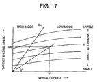
- the toroidal continuously variable gear mechanism is controlled to vary its gear ratio so as to gain a resultant transmission gear ratio or to provide a target engine speed which is determined on a control map specifying gear ratio change patterns according to vehicle running conditions including vehicle speeds and throttle positions.
- the gear ratio of the toroidal continuously variable gear mechanism is varied by controlling angles of inclination of the roller with respect to the toroidal surfaces of the input and output disks.
- two power transmission paths are organized such that a first power transmission path transmits engine output power to the drive wheels via a toroidal continuously variable gear mechanism and a planetary gear mechanism to reduce the resultant gear ratio as the toroidal continuously variable gear mechanism increases its gear ratio in forward speed ranges and a second power transmission path transmits engine output power to the drive wheels via the toroidal continuously variable gear mechanism only to reduce its gear ratio as the toroidal continuously variable gear mechanism reduces its gear ratio.
- the roller is inclined in a direction in which the toroidal continuously variable gear mechanism increases its gear ratio (this control of gear ratio is referred to as a low mode gear ratio control) after putting the continuously variable transmission in the first transmission path from the geared neutral position and subsequently in an opposite direction in which the toroidal continuously variable gear mechanism reduces its gear ratio (this control of gear ratio is referred to as a high mode gear ratio control) after putting the continuously variable transmission in the second transmission path.
- the toroidal continuously variable gear mechanism maintains inclinations of the roller within the specified limits of angle, preventing the continuously variable transmission from causing a drop in power transmission efficiency.
- this point is a characteristic point determined based on vehicle speeds and throttle openings and lies on a gear ratio control line set forth for each specific throttle opening.
- this line forms a mode switch line, an inclination angle of the line indicating the same resultant gear ratio described above.
- the continuously variable transmission changes the gear ratio control modes or the power transmission paths from one to another.
- the vehicle enters a slope repeatedly sloping up and down with an accelerator pedal remaining fixedly stepped on, i.e. with an throttle remaining open to a fixed position, the vehicle changes its speed according to the up and down slopes. If the vehicle speed changes repeatedly crossing the switch point, the continuously variable transmission switches the power transmission paths frequently, which always cause hunting of a switch of power transmission paths. Further, since the driver does not changes an accelerator pedal position, the driver feels shocks accompanying switches of the power transmission paths. This problem is common to continuously variable transmissions which selectively uses a plurality of power transmission paths.
- the control system for a continuously variable transmission disposed between an engine and drive wheels which incorporating a toroidal continuously variable gear mechanism continuously varies a gear ratio between an input speed from the engine and an output speed to the drive wheels of a vehicle according to gear ratio control patterns predetermined based on vehicle running conditions including a vehicle speed and engine loading and switches the transmission between a plurality of power transmission paths for transmitting engine output torque to the drive wheels, at least one of the power transmission paths including the toroidal continuously variable gear mechanism, which are selectively built up according to switching characteristics predetermined based on vehicle running conditions.
- the continuously variable transmission control system actuates switching means, such as friction coupling clutches, to selectively switch over the power transmission paths from one to another according to the predetermined switchover characteristics based on vehicle running conditions, and controlling the toroidal continuously variable gear mechanism according to the predetermined gear ratio control pattern selected based on vehicle running conditions.
- switching means such as friction coupling clutches
- the continuously variable transmission control system actuates switching means, such as friction coupling clutches, to selectively switch over the power transmission paths from one to another according to the predetermined switchover characteristics based on vehicle running conditions, and controlling the toroidal continuously variable gear mechanism according to the predetermined gear ratio control pattern selected based on vehicle running conditions.
- Each predetermined gear ratio control pattern being partly divided into two separate sections, one of which is used only during acceleration of the vehicle and another of which is used only during deceleration of the vehicle.
- the toroidal continuously variable gear mechanism may be of a toroidal continuously variable gear mechanism which is comprised of an input toroidal disk, an output toroidal disk and a roller disposed between the input and output toroidal disks and capable of inclining relative to the input and output toroidal disks and continuously varies a gear ratio between an input speed to the input toroidal disk from the engine and an output speed to the drive wheels from the output toroidal disk according to inclinations of the roller.
- the separate sections of the gear ratio control pattern are provided for a specified band of vehicle speeds including a specific vehicle speed at which the continuously variable transmission is switched between two different power transmission paths.
- the continuously variable transmission control system switches the continuously variable transmission from gear ratio control according to one section of a gear ratio control pattern to gear ratio control according to another section of the gear ratio control pattern when vehicle running condition turns from acceleration to deceleration or vice versa and maintains a gear ratio at the beginning of the switch of gear ratio control until the switch of gear ratio control is completed.
- the continuously variable transmission may built up simultaneously two power transmission paths, first one of which includes the toroidal continuously variable gear mechanism and another of which is free from the toroidal continuously variable gear mechanism in the neutral position. That is, in the neutral position, the toroidal continuously variable gear mechanism is controlled to provide an output speed through the first power transmission path such as to cancel an output speed through the other power transmission path.
- the toroidal continuously variable gear mechanism is controlled to vary a gear ratio according to different control patterns predetermined suitably for accelerating condition and decelerating condition, so that there is no hunting of switching the power transmission paths of the continuously variable transmission from one to another which is accompanied by shocks.
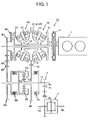
- the secondary shaft 13 mounts thereon a planetary gear mechanism 50 and two clutches, namely a low mode clutch 60 and a high mode clutch 70. There are low and high mode gear trains 80 and 90 between input shaft 11 and the secondary shaft 13.
- the first and second toroidal continuously variable gear mechanisms 20 and 30 have the same mechanism.
- Each toroidal continuously variable gear mechanism 20, 30 comprises an input disk 21, 31, an output disk 22, 32 and a pair of first and second roller 23, 33 between the input and output surfaces to transmit driving power from one to another.
- the input disks 21 and 31 are mounted on the primary shaft 12 by means of spline-engagement.
- the output disks 22 and 32 are formed integrally as one whole, which is hereafter referred to as an integrated output disk 34.
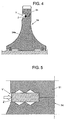
- the high mode first ring gear 91 may be united with the integrated output disk 34 together by plastic deformation in place of welding.
- each of the high mode first ring gear 91 and the integrated output disk 34 are formed with mating halves of a counter bore Y'.
- a connecting ring Z' made of a soft iron material is press-fitted into the counter bore Y' finished by knurling.
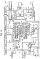
- the forward shift valve 220 has an outer sleeve 222 fitted for axial slide movement into an axial bore 221 (see Figure 11) formed in a valve body 111a of the hydraulic control section 111 of the shift control unit 110 and an inner sleeve 223 fitted for axial slide movement into the outer sleeve 222
- the reverse shift valve 230 has a sleeve 232 fitted for axial slide movement into an axial bore 231 (see Figure 11) formed in a valve body 111a of the hydraulic control section 111 of the shift control unit 110 and an inner sleeve 233 fitted for axial slide movement into the outer sleeve 232.
- the forward shift valve 220 has five ports, namely a line port 224 disposed at the middle in an axial direction and connected to the line pressure line 242, first and second relief ports 225 and 226 disposed at opposite ends and connected to the relief pressure line 203, a speed increase pressure port 227 disposed between the line pressure port 224 and the first relief port 225 and a speed reduction pressure port 228 disposed between the line pressure port 224 and the second relief port 226.
- the pressure lines 244 and 245 respectively extending from the speed increase pressure ports 227 and 237 of the forward and reverse shift valve 220 and 230 and the pressure lines 246 and 247 respectively extending from the speed reduction pressure ports 228 and 238 of the forward and reverse shift valve 220 and 230 are connected to the shift valve 241.
- Shift valve 241 places its valve spool to the right end position to bring the pressure lines 244 and 246 extending from the speed increase and reduction pressure ports 227 and 228 of the forward shift valve 220, respectively, into communication with a pressure line 248 leading to the speed increase pressure chambers 115 1 and 115 2 of the trunnion driving section 112 and a pressure line 249 leading to the speed reduction pressure chambers 116 1 and 116 2 of the trunnion driving section 112, respectively.
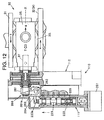
- Figures 11 and 12 show a cam mechanism 260 which moves axially each spool 223, 233 of the forward and reverse shift valves 220 and 230 against a return spring 229, 239 according to axial movement of the valve sleeve 222, 232 caused by a stepping motor 251, 252.
- the stepping motors 251 and 252 are connected to the valve sleeves 222 and 232 through connecting members 253 and 254, respectively.
- the cam mechanism 260 includes a cam 261, a shaft 262, a cam follower lever or slider 263 and drive levers 264 and 265.
- the cam 261 having a cam face 261a is mounted to a trunnion rod 27 of the trunnion 25 of the second toroidal continuously variable gear mechanism 30.
- the shaft 262 is disposed adjacent and perpendicularly to the valve spools 223 and 233 and supported for rotation by the valve body 111a of the hydraulic control section 111.
- the cam follower lever 263 is attached at one of its ends to the shaft and is forced at another end to contact with the cam face 261a of the cam 261.
- the drive lever 264 for forward shift is attached at one of its ends to the shaft 262 and is engaged at another end with an end key slot 223a of the valve spool 223 of the forward shift valve 220.
- the drive lever 265 for reverse shift is attached at one of its ends to the shaft 262 and is engaged at another end with an end key slot 233a of the valve spool 233 of the reverse shift valve 230.
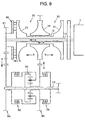
- the oil line 286 upstream from the cooler 285 is provided with an orifice 288 and a first switch valve 289 disposed in parallel.
- the bypass oil line 287 is provided with a second switch valve 290. Delivery of the lubrication oil to the first and second continuously variable transmission mechanisms 20 and 30 is controlled by means of the first and second switch valves 289 and 290.
- the second switch valve 290 closes to make the lubrication oil pass through the cooler before reaching the toroidal continuously variable gear mechanisms 20 and 30.
- the first switch valve 289 opens and closes according to incoming signals from the control unit 300. Specifically, the first switch valve 289 closes when, while the second switch valve 290 remains closed, the engine 1 operates at a speed of rotation lower than a specified speed of rotation and the vehicle runs at a velocity lower than a specified velocity.
- This hydraulic pressure difference control is performed to hold the trunnion 25 and roller 23 in the neutral positions against tractive force (T) exerted on the trunnion 25 or to force them in the axial direction X from the neutral position so as to vary the inclination of the roller for varying the gear ratio of the toroidal continuously variable gear mechanism 20.
- the gear ratio change of the toroidal continuously variable gear mechanism 30 is fixed at the gear ratio.
- the speed change is completed at a point of time that the valve spool 223 reaches the neutral position relative to the valve sleeve 222. Since the neutral position is the position to which the valve sleeve 222 has been shifted by the stepping motor 251 and corresponds to the inclined angle of the roller 23 caused by the cam mechanism 260, the position of the valve sleeve 222 corresponds to the inclined angle of the roller 23, and hence the trunnion 25. This means that the controlled variable of the stepping motor 251 determines the gear ratio of the toroidal continuously variable gear mechanism 20.
- the gear ratio of the toroidal continuously variable gear mechanism 20 is varied according to the number of pulses applied to the stepping motor 251.
- the gear ratio control of the toroidal continuously variable gear mechanism 30 is achieved in the same way when the valve sleeve 222 of the forward shift valve 220 has been shifted in the opposite direction. In this instance, the toroidal continuously variable gear mechanism 20 increases its gear ratio.
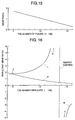
- Figure 15 shows the relationship between the number of pulses for the stepping motor 251, 252 and gear ratio of the toroidal continuously variable gear mechanism 20, 30. As apparent, the gear ratio of the toroidal continuously variable gear mechanism 20, 30 decreases with an increase in the number of pulses.
- Figure 16 shows the relationship between the number of pulses for the stepping motor 251, 252 and resultant gear ratio N of the continuously variable transmission 10 by the control of gear ratio of the toroidal continuously variable gear mechanism 20.
- the continuously variable transmission 10 provides a resultant gear ratio N which differs according to modes of gear ratio control, i.e. according to which mode clutch 60 or 70 has been locked.
- modes of gear ratio control i.e. according to which mode clutch 60 or 70 has been locked.
- the characteristic curve of resultant gear ratio N H of the continuously variable transmission 10 relative to the number of pulses agrees with the characteristic curve of gear ratio of the toroidal continuously variable gear mechanism 20, 30 shown in Figure 15. It is of course that the gear ratios of the toroidal continuously variable gear mechanisms 20 and are different from each other according to the difference in diameter of the first and second gears 91 and 92 of the high mode gear train 90 or the number of teeth between the first and second gears 91 and 92 of the high mode gear train 90.
- the continuously variable transmission 10 has two power transmission paths for transmitting engine output power to the drive wheels in the low mode gear ratio control in which the low mode clutch 60 is locked and the high mode clutch 70 is unlocked, i.e. the power transmission path between the input shaft 11 and the secondary shaft 13 which includes the loading cam 40, the toroidal continuously variable gear mechanisms 20 and 30, the high mode gear train 90 and the planetary gear mechanism 50 and the power transmission path between the input shaft 11 and the secondary shaft 13 which includes the low mode gear train 80 and the planetary gear mechanism 50 only, and single power transmission path in the high mode gear ratio control in which the low mode clutch 60 is unlocked and the high mode clutch 70 is locked, i.e.
- Po the current central value of the oscillation of gear ratio control pulses
- Pto the current amplitude of the oscillation of gear ratio control pulses given by the expression (VI)
- Wo the current angular velocity of rotation of the engine.
- the number of gear ratio control pulses P(t) is controlled in phase reversely to the oscillation or fluctuation of input rotation from the engine.
- control unit 300 is designed and adapted to perform extra gear ratio change control of the toroidal continuously variable gear mechanisms 20 and 30 such that the vehicle body is prevented from generating vibrations due to idling of the engine 1 in the non-drive range (which is hereafter referred to as non-drive range gear ratio control).
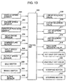
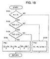
- Figure 19 is a flow chart illustrating a sequence routine of the non-drive range gear ratio control for a microcoprocessor of the control units 300.
- step S203 When the temperature of working oil in the continuously variable transmission 10 is equal to or higher than 0°C, another judgement is made at step S203 as to whether the engine 1 is put in an idle-up state.
- the term "idle-up state” as used herein shall means and refer to the state in which the engine 1 operates at a speed of rotation higher than an ordinary idle speed of rotation due to engine loading increased by actuation of an engine driven supplementary equipment such as an air-conditioning system while the idle switch 308 is turned on during idling.
- the toroidal continuously variable gear mechanisms 20 and 30 are controlled to provide a first gear ratio Ng1 at step S204.
- the toroidal continuously variable gear mechanisms 20 and 30 are controlled to provide a second gear ratio Ng2 at step S205. Further, when the temperature of working oil is lower than 0°C while the continuously variable transmission 10 is in the non-drive range, the toroidal continuously variable gear mechanisms 20 and 30 are controlled to provide a third gear ratio Ng3 at step S206.
- Ng1, Ng2 or Ng3 is lower than the gear ratio Ngo at starting in the drive (D) range, or on the higher speed side from the gear ratio Ngo at starting in the drive (D) range, the toroidal continuously variable gear mechanisms 20 and 30 yields high inertia, increasing resistance against rotation of the engine 1 with an effect of lowering fluctuations of rotation of the engine, which restraints vibrations of the vehicle body.
- a change in gear ratio of the toroidal continuously variable gear mechanisms 20 and 30 toward the higher speed side is smaller when the engine 1 is put in the idle-up state in which the engine 1 idles at an increased speed of rotation and causes increased resistance as compared with when the engine 1 is out of the idle-up state, which is desirable for the engine 1 to restrain aggravation of fuel consumption performance.
- the change in gear ratio toward the higher speed side may be increased when the engine 1 is in the idle-up state as compared with when the engine 1 is out of the idle-up state, as a result of which fluctuations of rotation of the engine is more lowered and the vehicle body is more effectively prevented from generating vibrations consequently.
- a change in gear ratio of the toroidal continuously variable gear mechanisms 20 and 30 toward the higher speed side is larger when the working oil is at temperatures as low as it has high viscosity to admit vibrations as compared with when it is at ordinary temperatures, as a result of which fluctuations of rotation of the engine is more lowered and the vehicle body is more effectively prevented from generating vibrations consequently.
- a change in gear ratio of the toroidal continuously variable gear mechanisms 20 and 30 toward the higher speed side may be smaller when the working oil is at low temperatures as compared with when it is at ordinary temperatures so as to prevent the engine 1 from bearing loading in excess.
- the gear ratio of the toroidal continuously variable gear mechanisms 20 and 30 may be periodically varied so as to cancel fluctuations of engine speed likely in the fluctuation reducing gear ratio control executed in the drive range.
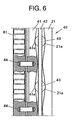
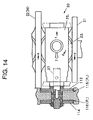
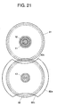
- the second gear 92 of the high mode gear train 90 may be provided with a massive disk member 92a such as a flywheel as shown in Figure 21 to generate inertia so as to lower fluctuations of rotation.
- the disk member 92a is desirably formed with circular-arcuate peripheral cuts 92c in diametrically opposite positions.
- the disk member 92a formed with the circular-arcuate peripheral cuts 92c permits the first gear 91 to be installed to the second gear 92 from the front with an effect of providing assembling facility.
- the control unit 300 searches an engine speed most suitable for running conditions dictated by vehicle speed and throttle opening and controls the toroidal continuously variable gear mechanisms 20 and 30 to vary a gear ratio based on the characteristic curves shown in Figure 16. Immediately after starting of the vehicle, the control unit 300 locks the low mode clutch 60 and unlocks the high mode clutch 70 to put the continuously variable transmission 10 in the low mode gear ratio control. When vehicle running conditions change crossing a mode switchover line Z into a high mode zone, the low mode clutch 60 and the high mode clutch 70 are unlocked and locked, respectively, to put the continuously variable transmission 10 in the high mode gear ratio control.
- the control unit 300 alternately locks and unlocks the high and low mode clutches 70 and 60. Since the gear ratio control curves L and H for the drive (D) mode dictate the same resultant gear ratio N when running conditions are on the mode switchover line Z, the continuously variable transmission 10 shifts between the high and low mode gear ratio control without causing felt shift shocks.
- control unit 300 is designed and adapted to perform switchover control of gear ratio control modes which prevents or significantly reduces an occurrence of unpleasant shift shocks.
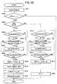
- Figure 22 is a flow chart illustrating a sequence routine of the gear ratio control mode switchover control for a microcoprocessor of the control units 300.
- step S301 When the flow chart logic commences and control proceeds directly to a function block at step S301 where signals from the sensors and switches 301 - 310 are read in. Subsequently, at step S302, an engine speed ESP transmitted to the continuously variable transmission 10 is compared with a switchover engine speed which is obtained by multiplying a current vehicle speed V by a gear ratio c on the mode switchover line Z to judge whether it is under a switchover of control mode.
- the engine speed ESP is approximately equal to the switchover engine speed c ⁇ V, this indicates that an alternation of locking and unlocking is in progress between the low and high mode clutches 60 and 70, then a resultant gear ratio N of the continuously variable transmission 10 is fixed at the gear ratio c on the mode switchover line Z at step S303.
- step S304 a judgement is subsequently made at step S304 as to whether the vehicle running conditions are in the high mode zone.
- a judgement is made at step S305 as to whether the vehicle is under deceleration.
- a judgement is subsequently made at step S310 as to whether the vehicle is acceleration.
- step S305 When it is determined at step S305 that the vehicle is under deceleration or it is determined at step S310 that the vehicle is not under acceleration, then another judgement is made at step S306 as to whether the result of the judgement made at step S305 in the last cycle of the sequence routine indicates acceleration. When the answer is affirmative, this indicates that the vehicle turns to deceleration for the first time in this cycle, then, the current gear ratio is fixed at step S307 and maintained until it is judged at step S308 that the vehicle speed V has reached a gear ratio control line for deceleration shown in Figure 23.
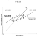
- Figure 23 shows one of gear ratio control lines for specific throttle opening of the gear ratio control map shown in Figure 17.
- the gear ratio control line includes separate acceleration line section and deceleration line section crossing the mode switchover line Z in a specified band of vehicle speeds.
- the acceleration line section specifies an engine speed on the high side for a specific vehicle speed
- the deceleration line section specifies an engine speed on the low side for the specific vehicle speed.
- the gear ratio control line is changed over from the acceleration line section to the deceleration line section.
- the gear ratio at the beginning of the changing of control line is remained.
- step S310 when it is determined at step S310 that the vehicle is under acceleration or it is determined at step S305 that the vehicle is not under deceleration, then another judgement is made at step S311 as to whether the result of the judgement made at step S310 in the last cycle of the sequence routine indicates deceleration.
- the current gear ratio is fixed at step S312 and maintained until it is judged at step S313 that the vehicle speed V has reached the acceleration line section.
- a target engine speed ESPO is determined according to the current vehicle speed V and throttle opening TVO at step S314.
- a speed difference ⁇ ESP of the target engine speed ESPO from the current engine speed ESP is determined at step S315, and a number of drive pulses ⁇ PLS necessary to remove the speed difference ⁇ ESP is subsequently determined at step S316.
- the stepping motor is driven with the drive pulses to attain the target engine speed ESPO.
- the gear ratio may be controlled correspondingly to a target engine speed jumping from a point X3 on the acceleration line section X directly to a point Y1 on the deceleration line section Y or from a point Y3 on the deceleration line section Y directly to a point X1 on the acceleration line section X as shown in Figure 23.
- switchover between the gear ratio control line sections is achieved in a short time, it takes a longer time until the target engine speed crosses the mode swichover line Z when it changes from the point Y1 or X1 than when it changes from the point Y2 or X2.
- the acceleration and deceleration line sections of the gear ratio control line are separately provided in a specified band of vehicle speeds in which the mode switchover line exists, the memory of the control unit 300 needs a reduced capacity for the gear ratio control map. If the band of vehicle speeds for the acceleration and deceleration line sections is narrow, the target engine speed changes with a high rate. Accordingly, the band of vehicle speeds is desirably specified in view of the memory capacity.
Landscapes
- Engineering & Computer Science (AREA)
- General Engineering & Computer Science (AREA)
- Mechanical Engineering (AREA)
- Control Of Transmission Device (AREA)
- Transmission Devices (AREA)
- Friction Gearing (AREA)
Applications Claiming Priority (3)
| Application Number | Priority Date | Filing Date | Title |
|---|---|---|---|
| JP24466497A JP3716569B2 (ja) | 1997-08-25 | 1997-08-25 | 無段変速機の制御装置 |
| JP24466497 | 1997-08-25 | ||
| JP244664/97 | 1997-08-25 |
Publications (2)
| Publication Number | Publication Date |
|---|---|
| EP0899485A1 true EP0899485A1 (de) | 1999-03-03 |
| EP0899485B1 EP0899485B1 (de) | 2003-05-14 |
Family
ID=17122125
Family Applications (1)
| Application Number | Title | Priority Date | Filing Date |
|---|---|---|---|
| EP98116026A Expired - Lifetime EP0899485B1 (de) | 1997-08-25 | 1998-08-25 | Steuereinrichtung für ein stufenloses Getriebe |
Country Status (6)
| Country | Link |
|---|---|
| US (1) | US6063002A (de) |
| EP (1) | EP0899485B1 (de) |
| JP (1) | JP3716569B2 (de) |
| KR (1) | KR19990023862A (de) |
| DE (1) | DE69814541T2 (de) |
| ES (1) | ES2200245T3 (de) |
Cited By (3)
| Publication number | Priority date | Publication date | Assignee | Title |
|---|---|---|---|---|
| DE19935991A1 (de) * | 1999-07-27 | 2001-03-15 | Nsk Ltd | Stufenlos verstellbare Getriebevorrichtung |
| EP1114952A1 (de) * | 2000-01-07 | 2001-07-11 | Nissan Motor Co., Ltd. | Stufenloses Getriebe |
| EP3234407A4 (de) * | 2011-04-18 | 2018-03-07 | Transmission CVT Corp Inc. | Stufenloses getriebe mit einem rollenlagerungsbereich |
Families Citing this family (34)
| Publication number | Priority date | Publication date | Assignee | Title |
|---|---|---|---|---|
| JP2000120822A (ja) * | 1998-10-21 | 2000-04-28 | Nsk Ltd | 無段変速装置 |
| JP4048625B2 (ja) * | 1998-12-15 | 2008-02-20 | 日産自動車株式会社 | 変速比無限大無段変速機の変速制御装置 |
| JP2000233668A (ja) * | 1999-02-16 | 2000-08-29 | Toyota Motor Corp | 車両の振動抑制装置 |
| JP3508689B2 (ja) * | 1999-07-27 | 2004-03-22 | 日産自動車株式会社 | 変速比無限大無段変速機の制御装置 |
| US6663532B1 (en) * | 1999-09-20 | 2003-12-16 | Transmisiones Tsp, S. A., De, C.V. | Dual strategy control for a toroidal drive type continuously variable transmission |
| JP3294230B2 (ja) * | 2000-02-22 | 2002-06-24 | 株式会社日立製作所 | 自動車用制御装置,自動車の制御方法,変速機 |
| JP2001271905A (ja) * | 2000-03-27 | 2001-10-05 | Honda Motor Co Ltd | トルクスプリット型無段変速機 |
| DE10033201A1 (de) * | 2000-07-07 | 2002-01-17 | Zf Batavia Llc | Hydraulisches System |
| US6393945B1 (en) * | 2000-09-21 | 2002-05-28 | Caterpillar Inc. | Apparatus and method for preventing hunting between ranges in a continuously variable transmission |
| JP4759887B2 (ja) * | 2001-09-07 | 2011-08-31 | 日産自動車株式会社 | 変速比無限大無段変速機の変速制御装置 |
| JP4867112B2 (ja) * | 2001-09-07 | 2012-02-01 | 日産自動車株式会社 | 変速比無限大無段変速機の変速制御装置 |
| DE10145643C1 (de) * | 2001-09-15 | 2002-11-07 | Case Steyr Landmaschinentechni | Regelung für den Antrieb einer Zapfwelle an einem Landfahrzeug |
| JP3758546B2 (ja) * | 2001-10-05 | 2006-03-22 | 日本精工株式会社 | 無段変速装置 |
| US7493203B2 (en) * | 2002-02-07 | 2009-02-17 | Luk Lamellen Und Kupplungsbau Beteiligungs Kg | Methods for regulating the gear ratio of an automatic power-branched transmission, and automatic power-branched transmission |
| JP3921148B2 (ja) * | 2002-08-07 | 2007-05-30 | ジヤトコ株式会社 | パワースプリット型無段変速装置 |
| DE102004003691B4 (de) * | 2004-01-24 | 2018-10-31 | Zf Friedrichshafen Ag | Kegelringgetriebe |
| DE102004013506A1 (de) * | 2004-03-19 | 2005-10-06 | Daimlerchrysler Ag | Verfahren zum Betrieb eines Antriebsstrangs für ein Kraftfahrzeug |
| US7105937B2 (en) * | 2004-07-14 | 2006-09-12 | Hamilton Sundstrand Corporation | Adjustable variable frequency starter/generator system |
| JP4244944B2 (ja) * | 2005-03-16 | 2009-03-25 | トヨタ自動車株式会社 | 車両用駆動装置の制御装置 |
| EP1953367B1 (de) * | 2007-01-31 | 2019-08-14 | Yamaha Hatsudoki Kabushiki Kaisha | Leerlaufdrehzahlregelung für einen Fahrzeugmotor |
| JP4983498B2 (ja) * | 2007-09-10 | 2012-07-25 | トヨタ自動車株式会社 | 無段変速機の制御装置 |
| JP4488062B2 (ja) | 2007-11-16 | 2010-06-23 | トヨタ自動車株式会社 | 駆動力源回転数制御装置 |
| US8257217B2 (en) * | 2009-02-03 | 2012-09-04 | Ford Global Technologies, Llc | Infinitely variable transmission with offset output shaft |
| AU2011312601B2 (en) * | 2010-10-04 | 2015-08-20 | Allison Transmission Inc. | System for selecting a transmission economy-based shift schedule |
| US9435409B2 (en) * | 2011-11-21 | 2016-09-06 | GM Global Technology Operations LLC | Variator output gearset |
| US9085225B2 (en) * | 2012-01-23 | 2015-07-21 | Dennis Ray Halwes | Infinitely variable transmission |
| JP5612624B2 (ja) * | 2012-03-08 | 2014-10-22 | 富士重工業株式会社 | レンジ切替装置 |
| US8888645B2 (en) * | 2012-07-31 | 2014-11-18 | Gm Global Technology Operations, Llc | Simple planetary gearset continuously variable transmission |
| GB201214316D0 (en) * | 2012-08-10 | 2012-09-26 | Torotrak Dev Ltd | Infinitely-variable transmission for a vehicle |
| JP5741553B2 (ja) * | 2012-11-02 | 2015-07-01 | トヨタ自動車株式会社 | 車両の制御装置 |
| JP6275849B2 (ja) * | 2014-07-23 | 2018-02-07 | アイシン・エィ・ダブリュ株式会社 | 自動変速機の油圧制御装置 |
| US9651127B2 (en) * | 2014-10-17 | 2017-05-16 | Allison Transmission, Inc. | Split power infinitely variable transmission architecture incorporating a planetary type ball variator with low part count |
| JP6474917B2 (ja) | 2015-12-09 | 2019-02-27 | アイシン・エィ・ダブリュ株式会社 | 自動変速機の油圧制御装置 |
| JP6561979B2 (ja) * | 2016-12-24 | 2019-08-21 | トヨタ自動車株式会社 | 車両用駆動装置の制御装置 |
Citations (4)
| Publication number | Priority date | Publication date | Assignee | Title |
|---|---|---|---|---|
| GB1603853A (en) * | 1978-05-08 | 1981-12-02 | British Leyland Cars Ltd | Variableratio transmissions |
| US4464952A (en) * | 1980-05-31 | 1984-08-14 | Bl Technology Limited | Control systems for continuously variable ratio transmissions (CVT) |
| EP0386746A1 (de) * | 1989-03-08 | 1990-09-12 | Nissan Motor Co., Ltd. | Getriebesteuerung |
| US5319999A (en) * | 1991-06-29 | 1994-06-14 | Mazda Motor Corporation | Control apparatus for stepless transmission for vehicles |
Family Cites Families (5)
| Publication number | Priority date | Publication date | Assignee | Title |
|---|---|---|---|---|
| JPS63130442A (ja) * | 1986-11-18 | 1988-06-02 | Nissan Motor Co Ltd | 無段変速機の変速制御装置 |
| JP2847779B2 (ja) * | 1989-07-24 | 1999-01-20 | 日産自動車株式会社 | 無段変速機 |
| JPH03223555A (ja) * | 1990-01-26 | 1991-10-02 | Nippon Seiko Kk | トロイダル型無段変速機 |
| US5213011A (en) * | 1991-04-05 | 1993-05-25 | Mazda Motor Corporation | Power transmission device for vehicle |
| JP3185400B2 (ja) * | 1992-09-18 | 2001-07-09 | 日産自動車株式会社 | 変速比無限大無段変速機の変速制御装置 |
-
1997
- 1997-08-25 JP JP24466497A patent/JP3716569B2/ja not_active Expired - Fee Related
-
1998
- 1998-08-25 KR KR1019980034509A patent/KR19990023862A/ko not_active Withdrawn
- 1998-08-25 US US09/139,667 patent/US6063002A/en not_active Expired - Fee Related
- 1998-08-25 ES ES98116026T patent/ES2200245T3/es not_active Expired - Lifetime
- 1998-08-25 EP EP98116026A patent/EP0899485B1/de not_active Expired - Lifetime
- 1998-08-25 DE DE69814541T patent/DE69814541T2/de not_active Expired - Fee Related
Patent Citations (4)
| Publication number | Priority date | Publication date | Assignee | Title |
|---|---|---|---|---|
| GB1603853A (en) * | 1978-05-08 | 1981-12-02 | British Leyland Cars Ltd | Variableratio transmissions |
| US4464952A (en) * | 1980-05-31 | 1984-08-14 | Bl Technology Limited | Control systems for continuously variable ratio transmissions (CVT) |
| EP0386746A1 (de) * | 1989-03-08 | 1990-09-12 | Nissan Motor Co., Ltd. | Getriebesteuerung |
| US5319999A (en) * | 1991-06-29 | 1994-06-14 | Mazda Motor Corporation | Control apparatus for stepless transmission for vehicles |
Cited By (6)
| Publication number | Priority date | Publication date | Assignee | Title |
|---|---|---|---|---|
| DE19935991A1 (de) * | 1999-07-27 | 2001-03-15 | Nsk Ltd | Stufenlos verstellbare Getriebevorrichtung |
| US6203466B1 (en) | 1999-07-27 | 2001-03-20 | Nsk Ltd. | Continuously variable transmission apparatus |
| DE19935991C2 (de) * | 1999-07-27 | 2002-07-18 | Nsk Ltd | Stufenlos verstellbare Getriebevorrichtung |
| EP1114952A1 (de) * | 2000-01-07 | 2001-07-11 | Nissan Motor Co., Ltd. | Stufenloses Getriebe |
| US6569051B2 (en) | 2000-01-07 | 2003-05-27 | Nissan Motor Co., Ltd. | Infinite speed ratio continuously variable transmission |
| EP3234407A4 (de) * | 2011-04-18 | 2018-03-07 | Transmission CVT Corp Inc. | Stufenloses getriebe mit einem rollenlagerungsbereich |
Also Published As
| Publication number | Publication date |
|---|---|
| EP0899485B1 (de) | 2003-05-14 |
| ES2200245T3 (es) | 2004-03-01 |
| JPH1163203A (ja) | 1999-03-05 |
| DE69814541D1 (de) | 2003-06-18 |
| KR19990023862A (ko) | 1999-03-25 |
| US6063002A (en) | 2000-05-16 |
| DE69814541T2 (de) | 2003-12-18 |
| JP3716569B2 (ja) | 2005-11-16 |
Similar Documents
| Publication | Publication Date | Title |
|---|---|---|
| EP0899485B1 (de) | Steuereinrichtung für ein stufenloses Getriebe | |
| US5980420A (en) | Control system for toroidal type continuously variable transmission | |
| EP0905413B1 (de) | Stufenloses toroidgetriebe | |
| US6030311A (en) | Control system for a continuously variable transmission | |
| CN102356254B (zh) | 动力传递装置 | |
| EP1336773B1 (de) | Fahrzeugsteuersystem | |
| JP3612773B2 (ja) | 無段変速機 | |
| JPS59110952A (ja) | 無段変速機の変速制御装置 | |
| JPS60255535A (ja) | 無段変速機付車輛の加速制御システム及び方法 | |
| JP3716568B2 (ja) | トロイダル式無段変速機 | |
| JP4329210B2 (ja) | 無段変速機の変速制御装置 | |
| KR100544220B1 (ko) | 최소의 오비터를 갖는 트랜스미션 | |
| JPH10267117A (ja) | トロイダル式無段変速機の制御装置 | |
| JP3713917B2 (ja) | 無段変速機の制御装置 | |
| JP3716542B2 (ja) | トロイダル式無段変速機 | |
| JPH1163184A (ja) | 無段変速機の制御装置 | |
| JP3157267B2 (ja) | 車両の動力伝達装置 | |
| JP2000179674A (ja) | パワートレインの制御装置 | |
| EP0969229A2 (de) | Stufenloses Getriebe | |
| JP2000179669A (ja) | パワートレインの制御装置 | |
| JPH10267118A (ja) | トロイダル式無段変速機の制御装置 | |
| JP4517451B2 (ja) | 無段変速機の制御装置 | |
| JP2848179B2 (ja) | 車両用自動変速機の油圧制御装置 | |
| KR19990054542A (ko) | 비례압력해제밸브를 이용한 벨트식 무단변속기의 유압제어장치 | |
| JPH0535783B2 (de) |
Legal Events
| Date | Code | Title | Description |
|---|---|---|---|
| PUAI | Public reference made under article 153(3) epc to a published international application that has entered the european phase |
Free format text: ORIGINAL CODE: 0009012 |
|
| AK | Designated contracting states |
Kind code of ref document: A1 Designated state(s): AT BE CH CY DE DK ES FI FR GB GR IE IT LI LU MC NL PT SE |
|
| AX | Request for extension of the european patent |
Free format text: AL;LT;LV;MK;RO;SI |
|
| 17P | Request for examination filed |
Effective date: 19990903 |
|
| AKX | Designation fees paid | ||
| 17Q | First examination report despatched |
Effective date: 20010214 |
|
| REG | Reference to a national code |
Ref country code: DE Ref legal event code: 8566 |
|
| GRAG | Despatch of communication of intention to grant |
Free format text: ORIGINAL CODE: EPIDOS AGRA |
|
| GRAG | Despatch of communication of intention to grant |
Free format text: ORIGINAL CODE: EPIDOS AGRA |
|
| GRAH | Despatch of communication of intention to grant a patent |
Free format text: ORIGINAL CODE: EPIDOS IGRA |
|
| GRAH | Despatch of communication of intention to grant a patent |
Free format text: ORIGINAL CODE: EPIDOS IGRA |
|
| GRAA | (expected) grant |
Free format text: ORIGINAL CODE: 0009210 |
|
| AK | Designated contracting states |
Designated state(s): DE ES FR GB IT |
|
| RBV | Designated contracting states (corrected) |
Designated state(s): DE ES FR GB IT |
|
| REG | Reference to a national code |
Ref country code: GB Ref legal event code: FG4D |
|
| REF | Corresponds to: |
Ref document number: 69814541 Country of ref document: DE Date of ref document: 20030618 Kind code of ref document: P |
|
| PGFP | Annual fee paid to national office [announced via postgrant information from national office to epo] |
Ref country code: GB Payment date: 20030730 Year of fee payment: 6 |
|
| PGFP | Annual fee paid to national office [announced via postgrant information from national office to epo] |
Ref country code: ES Payment date: 20030806 Year of fee payment: 6 |
|
| PGFP | Annual fee paid to national office [announced via postgrant information from national office to epo] |
Ref country code: FR Payment date: 20030814 Year of fee payment: 6 |
|
| REG | Reference to a national code |
Ref country code: ES Ref legal event code: FG2A Ref document number: 2200245 Country of ref document: ES Kind code of ref document: T3 |
|
| ET | Fr: translation filed | ||
| PLBE | No opposition filed within time limit |
Free format text: ORIGINAL CODE: 0009261 |
|
| STAA | Information on the status of an ep patent application or granted ep patent |
Free format text: STATUS: NO OPPOSITION FILED WITHIN TIME LIMIT |
|
| 26N | No opposition filed |
Effective date: 20040217 |
|
| PG25 | Lapsed in a contracting state [announced via postgrant information from national office to epo] |
Ref country code: GB Free format text: LAPSE BECAUSE OF NON-PAYMENT OF DUE FEES Effective date: 20040825 |
|
| PG25 | Lapsed in a contracting state [announced via postgrant information from national office to epo] |
Ref country code: ES Free format text: LAPSE BECAUSE OF NON-PAYMENT OF DUE FEES Effective date: 20040826 |
|
| GBPC | Gb: european patent ceased through non-payment of renewal fee |
Effective date: 20040825 |
|
| PG25 | Lapsed in a contracting state [announced via postgrant information from national office to epo] |
Ref country code: FR Free format text: LAPSE BECAUSE OF NON-PAYMENT OF DUE FEES Effective date: 20050429 |
|
| REG | Reference to a national code |
Ref country code: FR Ref legal event code: ST |
|
| PG25 | Lapsed in a contracting state [announced via postgrant information from national office to epo] |
Ref country code: IT Free format text: LAPSE BECAUSE OF NON-PAYMENT OF DUE FEES Effective date: 20050825 |
|
| REG | Reference to a national code |
Ref country code: ES Ref legal event code: FD2A Effective date: 20040826 |
|
| PGFP | Annual fee paid to national office [announced via postgrant information from national office to epo] |
Ref country code: DE Payment date: 20060817 Year of fee payment: 9 |
|
| PG25 | Lapsed in a contracting state [announced via postgrant information from national office to epo] |
Ref country code: DE Free format text: LAPSE BECAUSE OF NON-PAYMENT OF DUE FEES Effective date: 20080301 |