EP0895864A2 - Verfahren und Vorrichtung zum Ausstossen von Flüssigkeit - Google Patents
Verfahren und Vorrichtung zum Ausstossen von Flüssigkeit Download PDFInfo
- Publication number
- EP0895864A2 EP0895864A2 EP98306087A EP98306087A EP0895864A2 EP 0895864 A2 EP0895864 A2 EP 0895864A2 EP 98306087 A EP98306087 A EP 98306087A EP 98306087 A EP98306087 A EP 98306087A EP 0895864 A2 EP0895864 A2 EP 0895864A2
- Authority
- EP
- European Patent Office
- Prior art keywords
- liquid
- discharge
- droplet
- flow path
- droplets
- Prior art date
- Legal status (The legal status is an assumption and is not a legal conclusion. Google has not performed a legal analysis and makes no representation as to the accuracy of the status listed.)
- Granted
Links
Images


Classifications
-
- B—PERFORMING OPERATIONS; TRANSPORTING
- B41—PRINTING; LINING MACHINES; TYPEWRITERS; STAMPS
- B41J—TYPEWRITERS; SELECTIVE PRINTING MECHANISMS, i.e. MECHANISMS PRINTING OTHERWISE THAN FROM A FORME; CORRECTION OF TYPOGRAPHICAL ERRORS
- B41J2/00—Typewriters or selective printing mechanisms characterised by the printing or marking process for which they are designed
- B41J2/005—Typewriters or selective printing mechanisms characterised by the printing or marking process for which they are designed characterised by bringing liquid or particles selectively into contact with a printing material
- B41J2/01—Ink jet
- B41J2/21—Ink jet for multi-colour printing
- B41J2/2107—Ink jet for multi-colour printing characterised by the ink properties
- B41J2/211—Mixing of inks, solvent or air prior to paper contact
-
- B—PERFORMING OPERATIONS; TRANSPORTING
- B41—PRINTING; LINING MACHINES; TYPEWRITERS; STAMPS
- B41J—TYPEWRITERS; SELECTIVE PRINTING MECHANISMS, i.e. MECHANISMS PRINTING OTHERWISE THAN FROM A FORME; CORRECTION OF TYPOGRAPHICAL ERRORS
- B41J2/00—Typewriters or selective printing mechanisms characterised by the printing or marking process for which they are designed
- B41J2/005—Typewriters or selective printing mechanisms characterised by the printing or marking process for which they are designed characterised by bringing liquid or particles selectively into contact with a printing material
- B41J2/01—Ink jet
- B41J2/135—Nozzles
- B41J2/14—Structure thereof only for on-demand ink jet heads
- B41J2/14016—Structure of bubble jet print heads
- B41J2/14032—Structure of the pressure chamber
- B41J2/14056—Plural heating elements per ink chamber
-
- B—PERFORMING OPERATIONS; TRANSPORTING
- B41—PRINTING; LINING MACHINES; TYPEWRITERS; STAMPS
- B41J—TYPEWRITERS; SELECTIVE PRINTING MECHANISMS, i.e. MECHANISMS PRINTING OTHERWISE THAN FROM A FORME; CORRECTION OF TYPOGRAPHICAL ERRORS
- B41J2/00—Typewriters or selective printing mechanisms characterised by the printing or marking process for which they are designed
- B41J2/005—Typewriters or selective printing mechanisms characterised by the printing or marking process for which they are designed characterised by bringing liquid or particles selectively into contact with a printing material
- B41J2/01—Ink jet
- B41J2/135—Nozzles
- B41J2/14—Structure thereof only for on-demand ink jet heads
- B41J2002/14379—Edge shooter
-
- B—PERFORMING OPERATIONS; TRANSPORTING
- B41—PRINTING; LINING MACHINES; TYPEWRITERS; STAMPS
- B41J—TYPEWRITERS; SELECTIVE PRINTING MECHANISMS, i.e. MECHANISMS PRINTING OTHERWISE THAN FROM A FORME; CORRECTION OF TYPOGRAPHICAL ERRORS
- B41J2202/00—Embodiments of or processes related to ink-jet or thermal heads
- B41J2202/01—Embodiments of or processes related to ink-jet heads
- B41J2202/21—Line printing
Definitions
- the present invention relates to a liquid discharge method and a liquid jet apparatus for discharging liquid by use of energy generating devices. More particularly, the present invention relates to a liquid discharge method and a liquid jet apparatus for discharging a desired liquid by the action of bubbles to be created by causing thermal energy to act upon liquid.
- an ink jet recording method that is, the so-called bubble jet recording method, which performs the image formation in such a manner that energy, such as heat, is given to ink in the form of pulses in response to recording signals so as to create the change of states in ink with its abrupt voluminal changes to follow, and that ink is discharged from the discharge openings by the acting force based upon this change of states, thus adhering to a recording medium for the formation of images.
- the recording apparatus that uses this bubble jet recording method is generally provided with discharge openings for discharging ink; ink flow paths conductively connected with the discharge openings; and heat generating devices (electrothermal transducing devices) which are arranged in the ink flow paths as energy generating means for discharging ink as disclosed in the specifications of Japanese Patent Publication No. 61-59911, Japanese Patent Publication No. 61-59914, and U.S. Patent No. 4,723,129, among some others.
- this method makes it easier to obtain images in high resolution, and also, color images recorded by use of a smaller apparatus.
- the bubble jet recording method has been widely used for a printer, a copying machine, a facsimile equipment, or other office equipment in recent years. Furthermore, this method begins to be adopted even for a textile printing system or other systems for industrial use.
- a substance C created by the reaction of A + B ⁇ C changes to be C' when adhering to an object
- the substance C thus created is a material itself which is not stable in the formation of a pattern which is selectively made by the C' that adheres to the object.
- a first droplet containing A and a droplet containing B are discharged separately from different discharge openings and are caused to collide with each other during its flight to the object so that the A and B react upon themselves to create C. Then, immediately after that, the droplet that contains C is impacted on the object and changes to be C'.
- the liquid discharge method of the present invention is the one designed for a liquid jet head provided with first discharge openings, a first liquid flow path conductively connected with each of the first discharge openings, first energy generating devices for generating energy for the discharge of liquid droplets from the first discharge openings, second discharge openings, a second liquid flow path conductively connected with each of the second discharge openings, and second energy generating devices for generating energy for the discharge of liquid droplets from the second discharge openings.
- the second liquid droplet is discharged from the second discharge opening at a second discharge speed v 2 smaller than the first discharge speed, and before each of the liquid droplets being impacted on an object, the first liquid droplet and the second liquid droplet are allowed to collide with each other to be combined.
- the liquid jet apparatus of the present invention is provided with first discharge openings, a first liquid flow path conductively connected with each of the first discharge openings, first energy generating devices for generating energy for the discharge of liquid droplets from the first discharge openings, second discharge openings, a second liquid flow path conductively connected with each of the second discharge openings, and second energy generating devices for generating energy for the discharge of liquid droplets from the second discharge openings, and a driving circuit for driving the first energy generating devices and the second energy generating devices.
- the second liquid droplet is discharged from the second discharge opening at a second discharge speed smaller than the first discharge speed, and before each of the liquid droplets being impacted on an object, the first liquid droplet and the second liquid droplet is allowed to collide with each other to be combined.
- the respective differences in the impact position of the combined liquid droplets on the object, the individual impact position of the first liquid droplet on the object, and the individual impact position of the second liquid droplet on the object are within a range of less than the dot pitches of the pixel density to be output and used for recording images on the object.
- it should be less than 1/2 of the dot pitches. More preferably, it should be less than 1/3 thereof.
- the mass of the first liquid droplet should be larger than the mass of the second liquid droplet.
- first discharge speed v 1 and the second discharge speed v 2 satisfy a condition of v 1 / v 2 > 1.10.
- liquid supplied to the first liquid flow path and liquid supplied to the second liquid flow path are generally different from each other.
- these are ink different from each other in colorant densities or kinds of colorants thereof.
- the liquid jet head should preferably be provided with a plurality of first discharge openings and a plurality of second discharge openings corresponding to each of the first discharge openings, respectively, and as energy generating devices, it is preferable to use the bubble generating devices that generate bubbles in liquid and discharge liquid droplets by acting force thereof.
- the bubble generating device it is preferable to use heat generating devices to give heat to liquid for creation of bubbles. Then, as the heat generating devices, it is preferable to use electrothermal transducing devices.
- Figs. 1A and 1B are views which illustrate a liquid jet head to which the liquid discharge method is applicable in accordance with one embodiment of the present invention
- Fig. 1A is a cross-sectional view which shows the side end of the ink jet head in the flow path direction
- Fig. 1B is a perspective sectional view, observed from the upper surface.
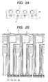
- Fig. 2A is a front view which shows one region of the orifice surface of the liquid jet head represented in Figs. 1A and 1B.
- Fig. 2B is a plan view which shows the circumferential area of the heat generating devices on an elemental substrate.
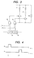
- Fig. 3 is a diagram which shows one example of the circuit that generates the driving pulses given to the heat generating device.
- Fig. 4 is a timing chart which shows one example of the driving timing of the heat generating device.
- Fig. 5 is a view which illustrates the liquid discharge method in accordance with the present invention.
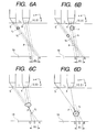
- Figs. 6A, 6B, 6C and 6D are views which illustrate the states of two droplets being combined as time elapses in accordance with the method represented in Fig. 5.
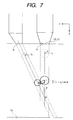
- Fig. 7 is a view which illustrates the liquid discharge method in accordance with the present invention.
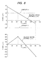
- Fig. 8 is a graph which shows the relationship between the relative distances and the overlap periods of ink droplets.
- Fig. 9 is a graph which shows the relationship between the relative distances and the overlap periods of ink droplets.
- Fig. 10 is a graph which shows the relationship between the relative distances and the overlap periods of ink droplets.
- Fig. 11 is a graph which shows the relationship between the relative distances and the overlap periods of ink droplets.
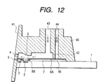
- Fig. 12 is a vertically sectional view which shows the entire structure of a liquid jet head.
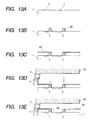
- Figs. 13A, 13B, 13C, 13D and 13E are views which schematically illustrate one example of the manufacturing process of the liquid jet head.
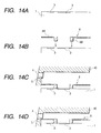
- Figs. 14A, 14B, 14C and 14D are views which schematically illustrate one example of the manufacturing process of the liquid jet head.
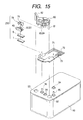
- Fig. 15 is an exploded perspective view which shows a liquid jet head cartridge.
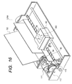
- Fig. 16 is a perspective view which schematically shows the structure of a liquid jet apparatus.
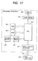
- Fig. 17 is a block diagram which shows the circuit structure of the apparatus represented in Fig. 16.
- Fig. 18 is a structural view which shows an ink jet recording system.
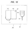
- Fig. 19 is a view which schematically shows a head kit.
- FIGs. 1A, 1B, 2A and 2B are views which illustrate a liquid jet head to which the liquid discharge method is applicable in accordance with one embodiment of the present invention
- Fig. 1A is a cross-sectional view which shows the side end of the ink jet head in the flow path direction
- Fig. 1B is a perspective sectional view, observed from the upper surface.
- Fig. 2A is a front view which shows one region of the orifice surface of this liquid jet head.
- Fig. 2B is a plan view which shows the circumferential area of the heat generating devices on an elemental substrate.
- the description will be made assuming that a liquid jet head is used as the ink jet recording head to be used for ink jet recording. It is of course possible to adopt this liquid jet head for any other uses than the ink jet recording.
- a first heat generating device 2 and a second heat generating device 3 are arranged in the direction of the flow path formation in order to give thermal energy for creating bubbles in liquid.
- the first heat generating device 2 is formed on the side farther away from the orifice face side (the face on which discharge openings 4 and 5 are formed as described later), and the second heat generating device 3 is formed on the side nearer to that face.
- the heat generating devices 2 and 3 are the electrothermal transducing devices the equivalent circuit of which is indicated by its electrical resistance.
- a second liquid flow path 7, which is conductively connected with a second discharge opening 5, is arranged.
- the first liquid flow path is formed by dry film, nickel, or resin such as polysulfone.
- the second liquid flow path 7 is formed by dry film or nickel.
- a correction resistor 21 shown in Fig. 1B is arranged in series with the second heat generating device 3 so as to enable each of the first heat generating device 2 and the second heat generating device 3 to obtain appropriate foaming by the same driving condition. Also, it is preferable to make a specific value of resistance larger for the correction resistor 21 in order to suppress the heat generation per unit area.
- a separation plate 8A and a separation plate 8B are arranged between the first liquid flow path 6 and the second liquid flow path 7 so that only the first heat generating device 2 is formed in the first liquid flow path 6, while only the second heat generating device 3 is formed in the second liquid flow path 7.
- this liquid jet head is formed by the first liquid flow path 6 and the second liquid flow path 7 in the form of two-story structure, and the first story portion (the second liquid flow path 7) and the second story portion (the first liquid flow path 6) are separated by means of the separation plate 8A.
- the portion where the first heat generating device is present is structured in a wellhole fashion which does not have any separation plate between the first and second story portions. Instead of such separation plate, a separation wall 8B is arranged on the side end of the first story portion having this wellhole structure. In this way, the second liquid flow path 7 is arranged to bypass the region of the first heat generating device 2 and to make the separation of the first liquid flow path 6 and the second liquid flow path 7.
- the liquid flow in the first liquid flow path 6 is indicated by an arrow F1
- the liquid flow in the second liquid flow path 7 is indicated by an arrow F2.
- the liquid in the first liquid flow path 6 flows into it from the back of the first liquid flow path 6 (the side opposite to the first discharge opening 4), and passes the surface of the first heat generating device 2.
- the liquid is then discharged from the first discharge opening 4 lastly.
- the liquid in the second liquid flow path 7 flows in from the back of the second liquid flow path 7, and flows along the side face of the separation wall 8B that surrounds the first heat generating device 2. Lastly, it is discharged from the second discharge opening 5.
- the separation wall 8B since the first liquid flow path 6 conductively connected with the first discharge opening 4 and the second liquid flow path 7 conductively connected with the second discharge opening 5 are separated by the separation wall 8B to be independent form each other, it is possible not only to prevent any crosstalks between the first liquid flow path 6 and the second liquid flow path 7, but also, to prevent the liquids in these two liquid flow paths from being mixed before the discharge thereof. Further, the liquid in the second liquid flow path 7 flows along the side face of the separation wall 8B to arrive on the surface of the second heat generating device 3. As a result, it becomes possible not only to prevent the heat accumulation on the second heat generating device 3, but to produce effect dually on the heat accumulation of the first heat generating device 2. In this way, the temperature rise is suppressed at the time of high frequency driving.
- the structure thus arranged it is possible to optimize the sizes of the heaters each formed in the respective liquid flow paths; the arrangement positions of heaters; the discharge opening configuration; and the area of the discharge openings. Then, it becomes possible to materialize a liquid jet head which is provided with the stable amount of droplets discharged from the first discharge opening 4 and the second discharge opening 5, discharge directions (the direction of the central axis of each discharge opening), and the discharge speed as well.
- the central axis of the first discharge opening 4 and that of the second discharge opening 5 are arranged to intersect each other on one point on the liquid jet head side rather than on the object side, such as a printing medium, that faces the liquid jet head.
- each of the droplets has a radius or a shape that can be regarded as a sphere fundamentally. Therefore, even if a structure is arranged so that the central axes of the discharge openings 4 and 5 are in the twisted positions, for example, it is possible to allow both droplets to collide with each other provided that the shortest distance between the central axes is smaller than the sum of the radii of both of them.
- a structure is arranged so that the central axes of the discharge openings 4 and 5 are in the twisted positions, for example, it is possible to allow both droplets to collide with each other provided that the shortest distance between the central axes is smaller than the sum of the radii of both of them.
- the present invention is also within the scope of the present invention.
- the liquid jet head of the present embodiment is structured so that the plural sets of the above-mentioned first liquid flow path 6 and the second liquid flow path 7 are arranged on the elemental substrate 1 in the transverse direction, and also, the plural numbers of the first discharge openings 4 and second discharge openings 5 are arranged on the orifice face also in the transverse direction, respectively. Therefore, on the surface of the elemental substrate 1, a plurality of the first heat generating devices 2 and the same numbers of the second heat generating devices 3 are arranged corresponding to the numbers of this set. In this case, a first common liquid chamber (at 42 in Fig.
- a second common liquid chamber (at 45 in Fig. 12) is arranged to be conductively connected with and shared by a plurality of second liquid flow paths 7 in order to supply liquid to each of the second liquid flow paths 7.
- Fig. 2B is a plan view which partly shows the circumference of the heat generating devices on the elemental substrate 1.
- the liquid jet head of the present embodiment does not use the separate substrates each for the first heat generating devices 2 and the second heat generating devices 3, respectively.
- the manufacturing process is not complicated, hence making it possible to maintain good production yield at lower costs.
- no correction resistor is used for the second heat generating device 3 as shown in Fig. 1B. In this mode, the conditional setting should be made for the voltage and pulse width in order to change the driving conditions.
- Fig. 3 is a circuit diagram which shows one example of the circuit that generates driving pulses given to the first heat generating device 2 and the second heat generating device 3.
- each of the heat generating devices 2 and 3, and the correction resistor 21 are represented by the symbol of electric resistance, respectively.
- Each one end of the heat generating devices 2 and 3 is connected with the positive pole of the electric supply source VM, and the other end thereof is connected with the respective collectors of the npn transistors Q1 and Q2.
- the respective emitters of the transistors Ql and Q2 are connected with the negative pole of the electric supply source VM. Also, there are arranged the two shift registers (S/R) 51 and 52, and the AND gate 53 that obtains AND of the output of one of the shift register 51 and the driving pulse P1, thus outputting it to the base of the transistor Q1, and also, the gate 54 that obtains AND of the output of the other shift register 52 and the driving pulse P2, thus outputting it to the base of the transistor Q2.
- the shift registers 51 and 52 develop serial data and transmit them to each of the heat generating devices 2 and 3.
- the timing of the driving pulses P1 and P2 is as shown in Fig. 4. As compared with the driving pulse P2, the driving pulse P1 is delayed by ⁇ T.
- the driving pulses P1 and P2 are inputted into the AND gates 53 and 54, the transistors (switching devices) Q1 and Q2 are turned on to supply current form the electric supply source VM to each of the heat generating devices 2 and 3 in accordance with the data from the shift registers 51 and 52.
- each of the heat generating devices 2 and 3 is driven in accordance with such time differential.
- FIG. 5 is a view schematically illustrating one example of the embodiment represented in Figs. 1A and 1B on the basis of the coordinate axes given below.
- the plural numbers of the first discharge openings 4 and the second discharge openings 5 are provided for the liquid jet head, respectively.
- the structure is arranged so that on the orifice face, each one of the first discharge openings 4 and the second discharge openings 5 form a pair, and the droplets discharged from the first discharge opening 4 and the second discharge opening 5, which belong to the same pair, are caused to collide with each other to be mixed during its flight, while no collision is allowed to take place between different pairs.
- Fig. 5 therefore, it is assumed that the first discharge opening 4 and the second discharge opening 5, which are arranged on the orifice face from the top to the bottom, and which belong to the same pair, are indicated as the first discharge opening 4 and the second discharge opening 5.
- the center of the first discharge opening 4 positioned on the orifice face is defined as the origin (0, 0), and the central axis of the first discharge opening 4 is defined as the axis Y, and that the axis perpendicular to the axis Y, which intersects the central axis of the second opening 5, is defined as the axis X.
- the angles formed by the perpendiculars to the discharge opening surface, the central axis of the first discharge opening 4, and the central axis of the second discharge opening 5 are defined as ⁇ 1 , and ⁇ 2 , respectively.
- the radius of the ink droplet discharged from the first discharge opening 4 is defined as r 1
- the radius of the ink droplet discharged from the second discharge opening 5 is defined as r 2 .
- the axis X is equivalent to the axis in the direction from the top to the bottom on the orifice face
- the axis Y is the axis directed from the first discharge opening 4 to an object, such as a printing medium.
- the orifice face and the object 19 are in parallel to each other. Therefore, the ⁇ 1 and ⁇ 2 may be regarded also as the angles formed by the perpendiculars to the impact positions on the object and the central axis of the first discharge opening 4 and the central axis of the second discharge opening 5. Also, the ⁇ 1 and ⁇ 2 may take a range of -90° ⁇ ⁇ 1 , ⁇ 2 ⁇ 90°. However, in each of the following expressions, the examination is carried out within a range of 0° ⁇ ⁇ 1 ⁇ ⁇ 2 ⁇ 90° to make understanding easier based upon the corresponding representation made in Fig. 5.
- the shootings may be made in some cases from each of the first and second discharge openings individually to the object, respectively. Therefore, although depending on the processing method of images, the above-mentioned ⁇ L should be less than the dot pitches of a desired image density or should preferably be less than 1/2 or more preferably less than 1/3.
- the center of the droplet actually discharged may deviate from the central axis of its discharge opening in some cases.
- the influence of deviation exerted by the droplet discharged from the first discharge opening which is faster than the droplet discharged from the second discharge opening, is made smaller than when the condition is set at ⁇ 1 > ⁇ 2 .
- this conditional arrangement is desirable, because if the momentum of the first droplet is larger than that of the second droplet, it becomes possible to make the deviation of impact positions smaller still when these droplets are combined.
- this arrangement is desirable, because the angular difference between the ⁇ 1 and the ⁇ 2 is less than 90°, hence making the variation of the ⁇ L smaller than the case where the angular difference between the ⁇ 1 and the ⁇ 2 is in the range of 90° or more even if the droplets, which are actually discharged from each of the discharge openings, should deviate from the central axes thereof.
- the first and second droplets are provided with an intersection region between the heads and the object.
- Fig. 5 the diameter of each of the droplets is shown in the same diameter of each of the discharge openings, because Fig. 5 is a schematic view to be used only for illustration.
- the diameter of discharged droplet is generally larger than that of the discharge opening. In this case, then, it becomes possible to deal with a slight variation of the discharge directions and speeds of droplets if an intersection region is provided for the projection surfaces themselves on the central axes of the respective discharge openings between the head and the object.
- the impact position of the droplet on the object 19, which has been created by the combination of the two droplets should be on the line segment that connects Q and R (at S in Figs. 6A to 6D) irrespective of the size of each of the two droplets and the discharge speeds without any consideration given to the variation of the discharge directions. Therefore, the differences between the impact position of the combined droplet and the impact positions of the first droplet and second droplets discharged as individual ones is smaller than ⁇ L 1 , respectively.
- the ⁇ L is less than the dot pitches of a desired image density, the differences between the impact of the combined droplet and the impact positions of the first and second droplets discharged as individual ones, respectively, becomes smaller than the dot pitches, hence making it possible to perform a gradation recording in high precision.
- the distance h 1 between the head and the object within a range of more than 0.2 mm and less than 3 mm in consideration of the fact that the object may be in contact with the head in the area where such region is less than 0.2 mm, particularly when the object is a paper sheet or the like which may be affected by the creation of cockling, and that if the distance is more than 3 mm, the influence exerted by the variation of discharge directions of droplets become greater.
- the distance L 1 there is favorably no need for making the ⁇ 1 of the smaller one larger than the ⁇ 2 .
- the head is produced in a size of more than 3 mm, it becomes necessary to make the ⁇ 2 larger than the ⁇ 1 within the range of h 1 described above, leading to the greater influence of the variation of the discharge directions of droplets.
- this distance it is desirable to make this distance within a range of more than 15 ⁇ m and less than 3 mm.
- the electrothermal transducing devices it is desirable to utilize the electrothermal transducing devices than the piezoelectric ones such as piezo elements or the like, because with the electrothermal transducing devices, the L 1 can be made smaller to control the influence that may be exerted by the variation of discharge directions of droplets more favorably.
- FIGs. 6A to 6D are the time series representation that illustrates each state of the two droplets being combined as described in conjunction with Fig. 5. The same reference marks are applied to the portions that shared by Fig. 5 in the description given below.
- the second droplet having the radius r 2 is discharged from the second discharge opening at the discharge speed V 2 preceding the droplet to be discharged from the first discharge opening. Then, with use of the driving circuit and others described earlier, the droplet having the radius r 1 is discharged from the first discharge opening at the discharge speed of v 1 (v 1 > v 2 ) with a delay ⁇ T after the droplet has been discharged from the second discharge opening at the discharge speed of v 2 as shown in Fig. 6B. Then, as shown in Fig. 6C, the two droplets are combined on the intersection region of the loci thereof.
- the droplet which shows almost sphere having the radius of r 3 moves at the speed of v 3 (v 1 ⁇ v 3 ⁇ v 2 ) so that the center thereof intersects the point S on the straight line between Q and R on the object 19.
- the time differential ⁇ T is set between the two droplets discharged from the two discharge openings, and then, the discharge speed is made faster for the droplet to be discharged later. Therefore, by setting the time differential ⁇ T appropriately, it is made easier to set condition for the speeds at which two droplets are discharged from the two discharge openings in order to combine them as more than when the condition should be set to discharge droplets at the same time. In this way, it becomes possible to provide a liquid jet apparatus and a liquid discharge method, which are capable of dealing with a slight variation of the speeds of liquid discharges.
- the momentum of the first droplet becomes greater than that of the second droplet.
- the impact position S on the object after the droplets have been combined is made closer to the impact position Q which the first droplet is supposed to arrive at if discharged to the object independently.
- the discharge amount of the first droplet (mass) w 1 is made larger than the discharge amount of the second droplet w 2 , it is desirable, because, then, the momentum of the first droplet can be made greater than the momentum of the second droplet.
- the impact position of the combined droplet may be deviated from the designated position due to the variation of the discharge speeds and directions of each of the droplets. Then, such deviation should be affected greater by the variation of the discharge speed and direction of the first droplet.
- ⁇ T in accordance with the v 1 and v 2 .
- the range of this ⁇ T is defined by seeking the condition ⁇ T so that a t should be present in order to make the center-to-center distance between the droplets smaller than the sum of the radii thereof, provided that the central positions of the droplets are given as t and ⁇ T, respectively.
- this range of ⁇ T can be expressed as given below using the h 1 , L 1 , ⁇ 1 , and ⁇ 2 shown in Fig. 5.
- the minimum value and the maximum value of the ⁇ T of the expression (3) are expressed by the time differential between discharges of droplets in order to allow them to be in contact with each other in the farthest region and the nearest region from the object, among the areas where the two droplets defined by the v 1 and v 2 may intersect each other (areas being partially aggregated by the intersection regions of the loci of the two droplets).
- the ⁇ T can be expressed by the expression given below using the L 1 , ⁇ 1 ⁇ 2 , v 1 , and v 2 shown in Fig. 5.
- f ( ⁇ i , r i , L 1 , ⁇ ) becomes smaller, if r 1 and r 2 are larger, the angular difference between the ⁇ 1 and ⁇ 2 is larger, the L 1 is smaller, and the speed variation ⁇ is smaller.
- the range of each of the discharge speeds should be set at 5 to 11 m/sec on the lower side, and 8 to 22 m/sec on the higher side.
- the central axes of the two discharge openings can form one plane, and at the same time, the surface of discharge openings and the object are in parallel with each other. Then, the present invention makes it possible to admit of a slight deviation resulting from the manufacture of heads and recording apparatuses as to the geometrical conditions which are the premises upon which the above description is set forth.
- This embodiment shows an example of a head which satisfies a condition with regard to AL among the above mentioned condition.
- the mode shown in Fig. 5 is prepared by use of piezo elements as means for discharging droplets.
- the distance to the paper sheet is set at 1.2 mm.
- the deviation between the impact position of the combined droplet and the impact positions of each of the droplets is controlled within 1/3 or less of the dot pitches of 70.5 ⁇ m in the pixel density of 360 dpi.
- the center-to-center distance is 38 ⁇ m between the first discharge opening 4 and the second discharge opening 5, while setting the angel ⁇ at 3°, which is formed by the center axis of the first discharge opening 4 and the second discharge opening 5.
- ink having high density of colorant (dyes of approximately 5w%) is supplied from the second common liquid chamber to the second liquid flow path 7, and the ink droplets are discharged from the second discharge opening 5 by applying electric pulses to the second heat generating device 3.
- it is arranged to supply the ink, which is provided with colorant of 1/16 of the density of ink to be supplied to the second liquid flow path 7, from the first common liquid chamber to the first liquid flow path 6, and then, by applying electric pulses to the first heat generating device 2, the ink droplets are discharged from the first discharge opening 4.
- the same kind of ink (colorant) and solvent that dissolves ink are used both for the first liquid flow path 6 and the second liquid flow path 7.
- the discharge amount (mass) of the ink droplet to be discharged from the first discharge opening 4, and the discharge speed are given as W 1 and v 1 , respectively.
- the discharge amount of the ink droplet to be discharged from the second discharge opening 5 and the discharge speed are given as W 2 and v 2 , respectively.
- nozzles for a first combination use nozzles are prepared so as to discharge an ink droplet in the discharge amount W 1 of 24 ng at the discharge speed of v 1 is 18 m/sec, and an ink droplet in the discharge amount W 2 of 16 ng and at the discharge speed of 9 m/sec, and then, to allow them to collide with each other in the flight thereof.
- nozzles are prepared so as to discharge an ink droplet in the discharge amount W 1 of 33.3 ng and at the discharge speed v 1 of 16 m/sec, and an ink droplet in the discharge amount W 2 of 6.7 ng and at the discharge speed of 8 m/sec, and then, to allow them to collide with each other in the flight thereof.
- These nozzles are manufactured for use of one and the same liquid jet head.
- nozzles are prepared each individually for the first discharge opening 4 and second discharge opening 5.
- the discharge amount of ink droplets and discharge speeds are set at 40 ng, and 14.5 m/sec, respectively, both for the discharge openings 1 and 2.
- Both the first and second combination nozzles present the fluctuation of the discharge speeds within a range of ⁇ 6% to 8%.
- the locus region of the ink droplet discharged from the second discharge opening 5 and the locus region of the ink droplet discharged from the first discharge opening 4 collide with each other reliably to mix both ink droplets within the range of the intersection region even if the discharge speeds fluctuate approximately ⁇ 10%.
- the speed of the flight after collision is 14.4 m/sec for the first combination nozzles, and the 14.7 m/sec for the second combination nozzles.
- Fig. 8 and Fig. 9 are graphs which illustrate the relationship between the relative distance between both ink droplets and the overlapping time T when ink droplets are discharged from both discharge openings 4 and 5 by use of the first combination nozzles.
- Fig. 8 shows the case where the discharge speed v 1 is increased by 10%, while the discharge speed v 2 is decreased by 10% from the numerical values described above.
- Fig. 9 shows the case where the discharge speed v 1 is decreased by 10%, while the discharge speed v 2 is increased by 10%.
- Fig. 10 and Fig. 11 are graphs which illustrate the relationship between the relative distance between both ink droplets and the overlapping time T when ink droplets are discharged from both discharge openings 4 and 5 by use of the second combination nozzles.
- Fig. 10 shows the case where the discharge speed v 1 is increased by 10%, while the discharge speed v 2 is decreased by 10% from the numerical values described above.
- Fig. 11 shows the case where the discharge speed v 1 is decreased by 10%, while the discharge speed v 2 is increased by 10%. From Fig. 10 and Fig. 11, it is understandable that both ink droplets are combined by means of the nozzles of the second combination.
- the liquid jet head provided with the above-mentioned first and second combination nozzles is installed on an ink jet recording apparatus as the ink jet recording head therefor. Then, the distance between the paper sheet serving as the object and each of the discharge openings is set at 1.2 mm for printing with the pixel density of 360 dpi (360 dots per 25.4 mm). As compared with the case where printing is carried out only with ink having approximately 5% colorant density, the OD (optical density) becomes 1/4 when only ink of 1/16 colorant density of that ink is used; the OD becomes 3/4 by use of the first combination nozzles; the OD becomes 1/2 by used of the second combination nozzles. Then, an image is obtained with a weighted ordinate gradation.
- the deviation of the impact position of the ink droplet on the surface of the paper sheet is approximately 7 ⁇ m by use of only the first combination nozzles; approximately 3 ⁇ m by use of only the second combination nozzles; and approximately 27 ⁇ m by use of only the second discharge opening 5.
- the dot pitches being 70.5 ⁇ m for the pixel density of 360 dpi, it is possible to output gradation images without degrading the image quality.
- Fig. 12 is a vertically sectional view which shows the entire structure of the liquid jet head.
- the grooved member 40 briefly comprises an orifice plate 41 provided with a first discharge opening 4 and a second discharge opening 5 arranged in the direction perpendicular to the elemental substrate 1; a plurality of grooves (not shown) that form a plurality of the first liquid flow paths 6; and a recessed portion that forms the first common liquid chamber 42 conductively connected with and shared by the plural first liquid flow paths 6 in order to supply liquid to each of the first liquid flow paths.
- the elemental substrate 1 is the substrate having on it a plurality of electrothermal transducing devices for generating heat to create film boiling in liquid for the formation of bubbles in it.
- a separation plate 8A is adhesively bonded on the lower side portion of this grooved member 40.
- a separation plate 8A is adhesively bonded on the lower side portion of this grooved member 40.
- This separation plate 8A is provided with apertures corresponding to the positions of the first heat generating devices 2 on the elemental substrate 1 to which this plate is bonded later.
- the elemental substrate 1 is bonded through the separation wall 8B that surrounds each of the first heat generating devices 2.
- each of the second liquid flow paths 7 which is conductively connected only with each of the second discharge openings 5, and which is arranged only with each second heat generating device 3 in the state of being completely separated from each of the first liquid flow paths 6.
- a second common liquid chamber 45 is made by a plurality of second liquid flow paths 7 being joined together for the formation thereof.
- the grooved member 40 thus arranged is provided with a first liquid supply path 43 that reaches the interior of the first common liquid chamber 42 from the upper portion of the grooved member 40 for the supply of the first liquid. Also, the grooved member 40 is provided with a second liquid supply path 44 that reaches the interior of the second common liquid chamber 45 from the upper portion of the grooved member 40 through the separation plate 8A.
- the first liquid is supplied to the first liquid common chamber 42 through the first liquid supply path 43, and then, supplied to the first liquid flow paths 6.
- the second liquid is supplied to the second liquid common chamber 45 through the second liquid supply path 44 and then, supplied to the second liquid flow paths 7.
- the second liquid supply path 44 is arranged in parallel with the first liquid supply path 43.
- the arrangement is not necessarily limited to this formation. If only the second liquid supply path is formed so that it can be conductively connected with the second common liquid chamber 45, the second liquid supply path may be arranged in anyway for the grooved member 40. Also, the thickness (diameter) of the second liquid supply path 44 is determined in consideration of the amount of supply of the second liquid. It is not necessarily to form this supply path circular, either. Rectangle or the like may be adoptable.
- the structure is arranged so that the supply of the second liquid to the second common liquid chamber 45 is carried out by means of the second liquid supply path 44 arranged in the direction which penetrates the separation plate 8A that separates the first liquid and the second liquid. Therefore, bonding of the separation plate 8A, the grooved member 40, and the elemental substrate 1 is made in one process at a time, thus making it easier to fabricate them in a better bonding precision, which will contribute to excellent discharges of droplets eventually.
- the second liquid is supplied to the second common liquid chamber 45 penetrating the separation plate 8A. This arrangement makes it possible to supply the second liquid to the second liquid flow paths 7 reliably, thus securing a sufficient amount of liquid to be supplied reliably for the execution of stabilized discharges.
- the flow path wall of the second liquid flow path 7 and the separation plate 8B that surrounds the first heat generating device 2 are formed on the elemental substrate 1.
- the separation plate 8A having the aperture on the position corresponding to the first heat generating device 2 is installed on the elemental substrate 1 thus arranged.
- the grooved member 40 is installed with grooves and others that form the first liquid flow path 6 or a head is manufactured in such a manner that after the formation of the flow path wall of the second liquid flow path 7 on the elemental substrate 1, a separation member formed integrally with the separation wall 8B and separation plate 8A is installed on this flow path wall, and then, the grooved member 40 is bonded to it.
- FIGs. 13A to 13E are cross-sectional views which schematically illustrate the manufacturing processes of a liquid jet head when a separation plate 8A and separation wall 8B are used after each of them is prepared individually.
- Figs. 14A to 14D are cross-sectional views which schematically illustrate the manufacturing processes of a liquid jet head using the separation member integrally formed by the separation plate 8A and the separation wall 8B.
- the separation wall 8B is formed to surround the first heat generating device 2 as shown in Fig. 13B.
- the separation plate 8A having a hole, which is open to the portion corresponding to the first heat generating device 2, is positioned, and then, it is bonded on the separation wall 8B.
- the grooved member 40 which is provided with the first discharge opening 4, the second discharge opening 5, and the first liquid flow path wall (not shown) formed on it, is positioned. Then, the grooved member is bonded under pressure to the separation member formed by the separation plate 8A and the separation wall 8B, thus completing the liquid jet head.
- the one shown in Figs. 14A to 14D makes it possible to eliminate the positioning and bonding processes of the separation plate 8A and separation wall 8B by using the separation member 8 instead, which is provided with the separation plate 8A and separation wall 8B integrally formed therefor. In this way, it becomes possible to materialize the enhancement of the production yield, and the reduction of costs at the same time.
- Fig. 15 is an exploded perspective view which schematically shows the liquid jet head cartridge including the liquid jet head described earlier.
- This liquid jet head cartridge is, briefly, formed by a liquid jet head unit 200 and a liquid container 80.
- the liquid jet head unit 200 comprises an elemental substrate 1, a separation member 8, a grooved member 40, a pressure spring 78, a liquid supply member 90, and a supporting member 70, among some others.
- a plurality of heat generating resistors heat generating devices
- a plurality of functional devices are arranged in order to drive these heat generating resistors selectively.
- the second liquid flow path is formed between this elemental substrate 1 and the separation member 8 as described earlier. The second liquid flows in this flow path. With the separation member 8 being bonded with the grooved member 40, the first liquid flow path is formed for the first liquid to flow.
- the pressure spring member 78 provides the grooved member 40 with biasing force acting in the direction toward the elemental substrate 1. With this biasing force, the elemental substrate 1, the separation member 8, and the grooved member 40, as well as the supporting member 70 which will be described later, are integrally formed together in good condition.
- the supporting member 70 supports the elemental substrate 1 and others. On this supporting member 70, there are further provided a contact pad 72 which is connected with the elemental substrate 1 to exchange electric signals with the printed-circuit board 71 that supplies electric signals, and which is also connected with the apparatus side to exchange electric signals with the apparatus side.
- the first liquid and the second liquid to be supplied to the liquid jet head are retained in its interior separately.
- the positioning unit 94 and the fixing shafts 95 are provided for the arrangement of a connecting member that connects the liquid jet head and the liquid container 90.
- the first liquid is supplied to the liquid supply path 81 of the liquid supply member from the liquid supply path 92 of the liquid container 90 through the supply path 84 of the connecting member, and then, supplied to the first common liquid chamber by way of the discharge liquid supply paths 83, 71, and 72 of each of the members.
- the second liquid is supplied to the liquid supply path 82 of the liquid supply member 80 from the supply path 93 of the liquid container 90 through the supply path of the connecting member, and then, supplied to the second common liquid chamber by way of the liquid supply paths 84, 71, and 72 of each of the members.
- Fig. 16 is a view which schematically shows the structure of a liquid jet apparatus having a liquid jet head mounted on it.
- IJRA ink jet recording apparatus IJRA that uses ink as the first and second liquids.
- a carriage HC of the liquid jet apparatus mounts on it a detachable head cartridge structured by a liquid tank unit 90 that retains ink and a liquid jet head unit 200.
- the carriage reciprocates in the width direction of a recording medium 150, such as a recording paper sheet, which is carried by means of a recording medium carrier.
- driving signals are supplied to the liquid jet head unit on the carriage HC from driving signal supply means (not shown), recording liquid is discharged from the liquid jet head to the recording medium in accordance with the driving signals.
- this recording apparatus is provided with a motor 111 that serves as a driving source, gears 112 and 113, a carriage shaft 115, and others that are needed for transmitting the power from the driving source to the carriage.
- Fig. 17 is a block diagram which shows the entire body of the recording apparatus that performs ink jet recording with the application of the liquid discharge method of the present invention.
- This recording apparatus receives printing information from a host computer 300 as control signals.
- the printing information is provisionally held on the input interface 301 arranged in the interior of the recording apparatus.
- the printing information is converted to the data executable by the recording apparatus, and inputted into the CPU 302 which dually serves as means for supplying head driving signals.
- the CPU 302 processes the data inputted to the CPU 302 using the RAM 304 and other peripheral units, thus converting them into the data to be printed (image data).
- the CPU 302 produces the motor driving data to drive the driving motor to move the recording sheet and the recording head in synchronism with the image data thus produced.
- the image data and motor driving data are transmitted to the head 200 and the driving motor 306 through the head driver 307 and the motor driver 305, respectively. Then, with the controlled timing, the head and motor are driven so that images are formed.
- the recording media which are usable by a recording apparatus of the kind for the provision of ink or other liquids thereon
- various kinds of paper and OHP sheets plastic material usable for compact disc, ornamental board, or the like, textiles, metallic materials such as aluminum, copper, leather material such as cowhide, hog hide, or artificial leather, wood material such as wood or plywood, bamboo material, ceramic material such as tiles, or three-dimensional products such as sponge.
- the above-mentioned recording apparatuses there are included a printing apparatus that records on various paper and OHP sheets, a recording apparatus for use of recording on compact discs and other plastic materials, a recording apparatus for use of recording on metal, such as a metallic plate, a recording apparatus for use of recording on leathers, a recording apparatus for use of recording on woods, a recording apparatus for use of recording on ceramics, a recording apparatus for use of recording on a three-dimensional netting structure, such as sponge, and also, textile printing apparatuses that record on textiles.
- the discharge liquid to be used for these liquid jet apparatuses it should be good enough to use the liquid which matches each of the recording media and recording conditions.
- Fig. 18 is a view which schematically illustrates the structure of this ink jet recording system.
- the liquid jet head of this ink jet recording system is a full line type head where a plurality of discharge openings are arranged at intervals (density) of 360 dpi (per 25.4 mm) in a length corresponding to the recordable width of the recording medium 150.
- Four liquid jet heads 201a, 201b, 201c, and 201d, each for yellow (Y), magenta (M), cyan (C), and black (Bk) are fixed and supported by a holder 202 in parallel with each other at given intervals in the direction X.
- signals are supplied from the head driver 307. On the basis of such signals, each of the liquid jet heads 201a to 201d is driven.
- each of the liquid jet heads 201a to 201d For each of the liquid jet heads 201a to 201d, four color ink of Y, M, C and Bk are supplied from each of the ink containers 204a to 204d as the first liquid. Also, dilution (the second liquid) for use of the ink that serves as the first liquid is retained in the dilution container 204e. Then, the arrangement is made to supply it to each of the liquid jet heads 201a to 201d. Also, on the lower part of each of the liquid jet heads 201a to 201d, there is arranged each of the head caps 203a to 203d having in it a sponge or some other ink absorbent, respectively. When recording is at rest, each of the liquid jet heads 201a to 201d is covered with each of the head caps 203a to 203d in order to keep each of them in good condition.
- a carrier belt 206 which constitutes carrier means for carrying various kinds of recording media as described earlier.
- the carrier belt 206 is drown around a given path by means of various rollers, and driven by driving rollers connected with a motor driver 305.
- a preprocessing apparatus 251 and a postprocessing apparatus 252 are provided on the upstream and downstream sides of the recording medium carrier path in order to give various treatments to the recording medium before and after recording, respectively.
- the preprocess and postprocess are different in its contents depending on the kinds of recording media, and also, on the kinds of ink to be used.
- the recording medium formed by metallic, plastic, or ceramic material, or the like for example, ultraviolet and ozone irradiation are given as the preprocessing thereof. In this way, the surface of the recording medium is activated to implement the enhancement of ink adhesion.
- an ionizer is used as a preprocessing device to remove the static electricity generated on the recording medium, because dust particles may easily adhere to the surface thereof, and such adhesion of dust particles may, in turn, hinder the normal performance of recording.
- textiles when textiles are used as a recording medium, it may be possible to provide textiles with a substance which is selective from among alkaline substance, water soluble substance, synthetic polymer, water soluble metallic salt, and thiourea with a view to enhancing the stain-resistance, the percentage exhaustion, or the like.
- the preprocessing is not necessarily limited to those mentioned here, but it may be possible to adopt a treatment that gives an appropriate temperature to a recording medium.
- the post-processing is such as to promote the fixation of ink by giving heat treatment, irradiation of ultraviolet rays, or the like to the recording medium on which ink has been provided, or such as to carry out a process to rinse away the processing agent that has adhered to the recording medium in the preprocessing but remains yet to be activated, among some others.
- the liquid jet head is not necessarily limited to the full line type. It may be possible to adopt a smaller liquid jet head described earlier, which is arranged to be in a mode that recording is performed by carrying the head in the width direction of a recording medium.
- Fig. 21 is a view which schematically shows such head kit.
- This head kit is arranged to house, in the kit container 501, a liquid jet head 510 provided with an ink discharge unit 511 for discharging ink; an ink container 520, which is separable or inseparable from the liquid jet head 510; and ink filling means 530 retaining ink to be filled into the ink container 520.
- the injection unit (injection needle and others) 531 of the ink filling means is partly inserted into the air communication opening 521 of the ink container 520, the connecting portion with the head, or the hole arranged to be open on the wall of ink container 520. Then, through such insertion part, ink in the ink filling means should be filled into the ink container.
- the liquid jet head, the ink container, and the ink filling means are housed in one kit container.
- ink is easily filled in the ink container immediately as described above to make it possible to begin recording at once.
- the description has been made in assumption that the ink filling means is included in the head kit, but as a head kit, it may be possible to adopt a mode in which only a separable type ink container having ink already filled in it, and the liquid jet head are housed in the kit container 510, but not any ink filling means.
- the present invention is not necessarily limited to this arrangement.
- the present invention is still applicable to a case where the surface of the discharge openings is not in parallel with the object or where the central axes of the first and second discharge openings are in the positions that may be twisted to each other. In such a case, by use of each of appropriate parameters, the respective conditions can be defined.
- the description has been made centering on the edge shooter type liquid jet head which is provided with discharge openings in the side position to the bubble generating areas, respectively.
- the present invention is of course applicable to the side shooter type liquid jet head or the like where the discharge openings are positioned to face the bubble generating areas or heat generating units.
- the example is illustrated in which one and the same colorant (ink) is dissolved in one and the same solvent, and only two kinds of liquid having different colorant densities are discharged from the first discharge opening 4 and the second discharge opening 5, respectively. Then, these droplets are caused to collide with each other to be mixed before being impacted on a recording medium.
- the present invention is not necessarily limited to this arrangement.
- As the combination of the liquids discharged from the first and second discharge openings various kinds of combination can be used.
- a combination of two kinds of liquids prepared by dissolving different dyes and pigments by use of one and the same solvent a combination of two kinds of liquids prepared by dissolving different colorants by use of different solvents; a combination of two kinds of liquids prepared by use of the pigment and bivalent metal or the like which may react upon each other; a combination of two kinds of liquids prepared by dissolving each one kind of two substances that react upon each other, such as anion surfactant or cation surfactant; a combination of the liquid having colorant dissolved in it and the liquid having the stabilizer for such colorant dissolved in it; and a combination of the liquid prepared by dissolving colorant and only solvent, among some others.
- the present invention is more effective, because liquid droplets can be combined themselves reliably to react upon each other by setting the discharge speed and discharge timing appropriately (for example, if the reaction period of the liquids is longer, the combination position of the two droplets is made nearer to the head side, while the discharge speed is made slower) so as to satisfy the reaction period within a range of each condition by the application of the liquid discharge method described above.
- the combination to be implemented for a gradation recording it is possible to allow the droplets from both of the discharge openings to collide with each other reliably before being impacted on an object by the predetermined discharge speeds for the combination of the two discharge openings even if discharge speeds may fluctuate, and also, it is made possible to minimize the deviation of impact position. Therefore, a good gradation image can be output in high quality.
Landscapes
- Particle Formation And Scattering Control In Inkjet Printers (AREA)
- Ink Jet (AREA)
- Ink Jet Recording Methods And Recording Media Thereof (AREA)
Applications Claiming Priority (6)
| Application Number | Priority Date | Filing Date | Title |
|---|---|---|---|
| JP206553/97 | 1997-07-31 | ||
| JP20655397 | 1997-07-31 | ||
| JP20655397 | 1997-07-31 | ||
| JP10190437A JPH1199651A (ja) | 1997-07-31 | 1998-07-06 | 液体吐出方法及び液体吐出装置 |
| JP190437/98 | 1998-07-06 | ||
| JP19043798 | 1998-07-06 |
Publications (3)
| Publication Number | Publication Date |
|---|---|
| EP0895864A2 true EP0895864A2 (de) | 1999-02-10 |
| EP0895864A3 EP0895864A3 (de) | 1999-09-15 |
| EP0895864B1 EP0895864B1 (de) | 2004-06-30 |
Family
ID=26506081
Family Applications (1)
| Application Number | Title | Priority Date | Filing Date |
|---|---|---|---|
| EP98306087A Expired - Lifetime EP0895864B1 (de) | 1997-07-31 | 1998-07-30 | Verfahren und Vorrichtung zum Ausstossen von Flüssigkeit |
Country Status (7)
| Country | Link |
|---|---|
| US (1) | US6164748A (de) |
| EP (1) | EP0895864B1 (de) |
| JP (1) | JPH1199651A (de) |
| CN (1) | CN1079737C (de) |
| AU (1) | AU746793B2 (de) |
| CA (1) | CA2243913C (de) |
| DE (1) | DE69824796T2 (de) |
Cited By (5)
| Publication number | Priority date | Publication date | Assignee | Title |
|---|---|---|---|---|
| EP1369248A1 (de) * | 2002-06-03 | 2003-12-10 | Sony Corporation | Flüssigkeitsausstossvorrichtung und Flüssigkeitsausstossverfahren |
| EP1398155A1 (de) * | 2002-09-10 | 2004-03-17 | Brother Kogyo Kabushiki Kaisha | Vorrichtung zum Ausstoss sehr kleiner Tröpfchen |
| EP1574343A3 (de) * | 2004-03-10 | 2006-09-06 | Brother Kogyo Kabushiki Kaisha | Tröpfchenausstossgerät |
| WO2007031108A1 (en) * | 2005-09-14 | 2007-03-22 | Societe Bic | A multi-nozzle liquid droplet ejecting head, a writing instrument comprising such a head, and a method of ejecting liquid droplets from same |
| GB2555470A (en) * | 2016-10-31 | 2018-05-02 | Piotr Jeute | A drop on demand printing head and printing method |
Families Citing this family (12)
| Publication number | Priority date | Publication date | Assignee | Title |
|---|---|---|---|---|
| US6494563B2 (en) | 1997-12-25 | 2002-12-17 | Canon Kabushiki Kaisha | Ink jet element substrate and ink jet head that employs the substrate, and ink jet apparatus on which the head is mounted |
| JP2001186880A (ja) * | 1999-10-22 | 2001-07-10 | Ngk Insulators Ltd | Dnaチップの製造方法 |
| JP2004001364A (ja) * | 2002-04-16 | 2004-01-08 | Sony Corp | 液体吐出装置及び液体吐出方法 |
| JP4599871B2 (ja) * | 2003-06-30 | 2010-12-15 | ブラザー工業株式会社 | 液滴噴射装置 |
| CN101263009B (zh) * | 2005-09-14 | 2010-05-26 | Bic公司 | 包含多喷嘴液滴喷出头的写入设备以及其喷出液滴的方法 |
| DE102006045060A1 (de) * | 2006-09-21 | 2008-04-10 | Kba-Metronic Ag | Verfahren und Vorrichtung zur Erzeugung von Tintentropfen mit variablen Tropfenvolumen |
| EP2058130A1 (de) * | 2007-11-09 | 2009-05-13 | Nederlandse Organisatie voor toegepast- natuurwetenschappelijk onderzoek TNO | Tröpfchenauswahlmechanismus |
| EP2058131A1 (de) * | 2007-11-09 | 2009-05-13 | Nederlandse Organisatie voor toegepast- natuurwetenschappelijk onderzoek TNO | Tröpfchenauswahlmechanismus |
| US20100156998A1 (en) * | 2008-12-19 | 2010-06-24 | Nobuo Matsumoto | Method and apparatus for printing |
| JP5686464B2 (ja) * | 2010-06-29 | 2015-03-18 | 富士フイルム株式会社 | 液体吐出ヘッド、液体吐出装置及びインクジェット印刷装置 |
| ES2862471T3 (es) * | 2016-08-04 | 2021-10-07 | Jeute Piotr | Un cabezal de impresión por goteo bajo demanda y un procedimiento de impresión |
| JP2021070880A (ja) * | 2019-10-30 | 2021-05-06 | セイコーエプソン株式会社 | インクジェット記録方法 |
Citations (3)
| Publication number | Priority date | Publication date | Assignee | Title |
|---|---|---|---|---|
| JPS6159914A (ja) | 1984-08-31 | 1986-03-27 | Fujitsu Ltd | デイジタル圧縮装置 |
| JPS6159911A (ja) | 1984-08-30 | 1986-03-27 | Nec Corp | 切換スイツチ回路 |
| US4723129A (en) | 1977-10-03 | 1988-02-02 | Canon Kabushiki Kaisha | Bubble jet recording method and apparatus in which a heating element generates bubbles in a liquid flow path to project droplets |
Family Cites Families (12)
| Publication number | Priority date | Publication date | Assignee | Title |
|---|---|---|---|---|
| JPS57185159A (en) * | 1981-05-11 | 1982-11-15 | Nec Corp | Ink jet recorder |
| US5285215A (en) * | 1982-12-27 | 1994-02-08 | Exxon Research And Engineering Company | Ink jet apparatus and method of operation |
| DE3416449A1 (de) * | 1983-08-01 | 1985-02-14 | Veb Kombinat Robotron, Ddr 8012 Dresden | Verfahren zum aufzeichnen von informationen oder bildern mittels tintenstrahlschreiber |
| US4908638A (en) * | 1988-12-15 | 1990-03-13 | Xerox Corporation | Ink jet marking head having multicolor capability |
| US5208605A (en) * | 1991-10-03 | 1993-05-04 | Xerox Corporation | Multi-resolution roofshooter printheads |
| JP3127646B2 (ja) * | 1993-01-07 | 2001-01-29 | 富士ゼロックス株式会社 | インクジェット記録装置 |
| KR970011650B1 (en) * | 1994-01-10 | 1997-07-12 | Samsung Electronics Co Ltd | Fabrication method of good die of solder bump |
| US5606351A (en) * | 1994-06-20 | 1997-02-25 | Eastman Kodak Company | Altering the intensity of the color of ink jet droplets |
| JPH08230215A (ja) * | 1994-12-28 | 1996-09-10 | Sony Corp | プリントヘッド及びこれを用いた印刷方法 |
| DE69601318T2 (de) * | 1995-04-14 | 1999-08-26 | Sony Corp | Druckvorrichtung |
| US5821962A (en) * | 1995-06-02 | 1998-10-13 | Canon Kabushiki Kaisha | Liquid ejection apparatus and method |
| US5889538A (en) * | 1995-11-24 | 1999-03-30 | Oki Data Corporation | Ink jet recording apparatus |
-
1998
- 1998-07-06 JP JP10190437A patent/JPH1199651A/ja active Pending
- 1998-07-24 US US09/122,330 patent/US6164748A/en not_active Expired - Fee Related
- 1998-07-27 CA CA002243913A patent/CA2243913C/en not_active Expired - Fee Related
- 1998-07-30 AU AU78622/98A patent/AU746793B2/en not_active Ceased
- 1998-07-30 DE DE69824796T patent/DE69824796T2/de not_active Expired - Lifetime
- 1998-07-30 EP EP98306087A patent/EP0895864B1/de not_active Expired - Lifetime
- 1998-07-31 CN CN98116763A patent/CN1079737C/zh not_active Expired - Fee Related
Patent Citations (3)
| Publication number | Priority date | Publication date | Assignee | Title |
|---|---|---|---|---|
| US4723129A (en) | 1977-10-03 | 1988-02-02 | Canon Kabushiki Kaisha | Bubble jet recording method and apparatus in which a heating element generates bubbles in a liquid flow path to project droplets |
| JPS6159911A (ja) | 1984-08-30 | 1986-03-27 | Nec Corp | 切換スイツチ回路 |
| JPS6159914A (ja) | 1984-08-31 | 1986-03-27 | Fujitsu Ltd | デイジタル圧縮装置 |
Cited By (13)
| Publication number | Priority date | Publication date | Assignee | Title |
|---|---|---|---|---|
| US6916077B2 (en) | 2002-06-03 | 2005-07-12 | Sony Corporation | Liquid ejecting device and liquid ejecting method |
| SG130008A1 (en) * | 2002-06-03 | 2007-03-20 | Sony Corp | Liquid ejecting device and liquid ejecting method |
| EP1369248A1 (de) * | 2002-06-03 | 2003-12-10 | Sony Corporation | Flüssigkeitsausstossvorrichtung und Flüssigkeitsausstossverfahren |
| US7198344B2 (en) | 2002-06-03 | 2007-04-03 | Sony Corporation | Liquid ejecting device and liquid ejecting method |
| EP1398155A1 (de) * | 2002-09-10 | 2004-03-17 | Brother Kogyo Kabushiki Kaisha | Vorrichtung zum Ausstoss sehr kleiner Tröpfchen |
| US7004555B2 (en) | 2002-09-10 | 2006-02-28 | Brother Kogyo Kabushiki Kaisha | Apparatus for ejecting very small droplets |
| US7954916B2 (en) | 2004-03-10 | 2011-06-07 | Brother Kogyo Kabushiki Kaisha | Droplet ejecting apparatus for forming dots on a medium |
| EP1574343A3 (de) * | 2004-03-10 | 2006-09-06 | Brother Kogyo Kabushiki Kaisha | Tröpfchenausstossgerät |
| WO2007031108A1 (en) * | 2005-09-14 | 2007-03-22 | Societe Bic | A multi-nozzle liquid droplet ejecting head, a writing instrument comprising such a head, and a method of ejecting liquid droplets from same |
| US7997719B2 (en) | 2005-09-14 | 2011-08-16 | Societe Bic | Multi-nozzle liquid droplet ejecting head, a writing instrument comprising such a head, and a method of ejecting liquid droplets from same |
| AU2005336471B2 (en) * | 2005-09-14 | 2011-10-06 | Societe Bic | A multi-nozzle liquid droplet ejecting head, a writing instrument comprising such a head, and a method of ejecting liquid droplets from same |
| GB2555470A (en) * | 2016-10-31 | 2018-05-02 | Piotr Jeute | A drop on demand printing head and printing method |
| GB2555470B (en) * | 2016-10-31 | 2021-09-15 | Piotr Jeute | A drop on demand printing head and printing method |
Also Published As
| Publication number | Publication date |
|---|---|
| CA2243913C (en) | 2003-09-30 |
| DE69824796D1 (de) | 2004-08-05 |
| CN1207342A (zh) | 1999-02-10 |
| CA2243913A1 (en) | 1999-01-31 |
| AU7862298A (en) | 1999-02-11 |
| US6164748A (en) | 2000-12-26 |
| AU746793B2 (en) | 2002-05-02 |
| CN1079737C (zh) | 2002-02-27 |
| JPH1199651A (ja) | 1999-04-13 |
| EP0895864A3 (de) | 1999-09-15 |
| EP0895864B1 (de) | 2004-06-30 |
| DE69824796T2 (de) | 2005-07-07 |
Similar Documents
| Publication | Publication Date | Title |
|---|---|---|
| EP0895864B1 (de) | Verfahren und Vorrichtung zum Ausstossen von Flüssigkeit | |
| JP3472030B2 (ja) | 液体吐出ヘッドの製造方法並びに液体吐出ヘッド、該液体吐出ヘッドを用いたヘッドカートリッジ、液体吐出装置及びヘッドキット | |
| EP0913257B1 (de) | Vorrichtung zur Erzeugung des Tintenausstosses und des Nachfüllens der Tintenkammer mit hoher Frequenz | |
| JP3696967B2 (ja) | 液体吐出ヘッド、液体吐出ヘッドを用いたヘッドカートリッジ、液体吐出装置、液体吐出方法および記録方法 | |
| US6099109A (en) | Liquid-ejecting head and method of manufacturing the same | |
| KR20190002324A (ko) | 액체 토출 헤드 및 액체 토출 장치 | |
| US6231156B1 (en) | Ink-jet printing apparatus and ejection recovery method of printing head | |
| EP0913259B1 (de) | Apparat zum generieren kleinvolumiger Hochgeschwindigkeitstropfen in einem Tintenstrahldrucker | |
| CA2207166C (en) | Liquid discharging method, liquid supplying method, liquid discharge head, liquid discharge head cartridge using such liquid discharge head, and liquid discharge apparatus | |
| US6527376B1 (en) | Liquid-ejecting head, liquid-ejecting method and liquid-ejecting printing apparatus | |
| JP2004001488A (ja) | インクジェットヘッド | |
| JP3554099B2 (ja) | インクジェットプリント装置 | |
| JPH0911471A (ja) | 液体吐出方法、液体吐出ヘッド、ヘッドカートリッジ、液体吐出装置、及び液体吐出ヘッドキット | |
| EP0819530B1 (de) | Flüssigkeitsausstosskopf, einen solchen Kopf verwendende Kassette, Flüssigkeitsausstossapparat, Verfahren zum Ausstossen von Flüssigkeit und Kit für einen Flüssigkeitsausstosskopf | |
| JP3592101B2 (ja) | 液体吐出方法及び液体吐出ヘッド並びに液体吐出装置 | |
| JP3413063B2 (ja) | 液体吐出方法及び液体吐出ヘッド | |
| JPH1076661A (ja) | インクジェットプリント方法および装置 | |
| US20020196299A1 (en) | Liquid ejection head and image-forming device using the same | |
| JP3639698B2 (ja) | 液体吐出ヘッド、ヘッドカートリッジ、液体吐出記録装置、および液体吐出ヘッドの製造方法 | |
| JPH09136417A (ja) | 液体吐出ヘッドおよび液体吐出装置 | |
| JP3563999B2 (ja) | 液体吐出方法,液体吐出ヘッドおよび液体吐出装置 | |
| JPH10226075A (ja) | インクジェット記録装置およびインクジェット記録方法 | |
| JPH1024564A (ja) | 液体吐出記録方法及び液体吐出ヘッド | |
| JP2002210973A (ja) | インクジェットプリントヘッド | |
| JPH1029309A (ja) | 液体吐出ユニットの製造方法、液体吐出ヘッドおよび液体吐出装置 |
Legal Events
| Date | Code | Title | Description |
|---|---|---|---|
| PUAI | Public reference made under article 153(3) epc to a published international application that has entered the european phase |
Free format text: ORIGINAL CODE: 0009012 |
|
| AK | Designated contracting states |
Kind code of ref document: A2 Designated state(s): DE ES FR GB IT NL |
|
| AX | Request for extension of the european patent |
Free format text: AL;LT;LV;MK;RO;SI |
|
| PUAL | Search report despatched |
Free format text: ORIGINAL CODE: 0009013 |
|
| AK | Designated contracting states |
Kind code of ref document: A3 Designated state(s): AT BE CH CY DE DK ES FI FR GB GR IE IT LI LU MC NL PT SE |
|
| AX | Request for extension of the european patent |
Free format text: AL;LT;LV;MK;RO;SI |
|
| RIC1 | Information provided on ipc code assigned before grant |
Free format text: 6B 41J 2/14 A, 6B 41J 2/205 B, 6B 41J 2/21 B |
|
| 17P | Request for examination filed |
Effective date: 20000128 |
|
| AKX | Designation fees paid |
Free format text: DE ES FR GB IT NL |
|
| 17Q | First examination report despatched |
Effective date: 20020802 |
|
| GRAP | Despatch of communication of intention to grant a patent |
Free format text: ORIGINAL CODE: EPIDOSNIGR1 |
|
| GRAS | Grant fee paid |
Free format text: ORIGINAL CODE: EPIDOSNIGR3 |
|
| GRAA | (expected) grant |
Free format text: ORIGINAL CODE: 0009210 |
|
| AK | Designated contracting states |
Kind code of ref document: B1 Designated state(s): DE ES FR GB IT NL |
|
| PG25 | Lapsed in a contracting state [announced via postgrant information from national office to epo] |
Ref country code: NL Free format text: LAPSE BECAUSE OF FAILURE TO SUBMIT A TRANSLATION OF THE DESCRIPTION OR TO PAY THE FEE WITHIN THE PRESCRIBED TIME-LIMIT Effective date: 20040630 Ref country code: IT Free format text: LAPSE BECAUSE OF FAILURE TO SUBMIT A TRANSLATION OF THE DESCRIPTION OR TO PAY THE FEE WITHIN THE PRESCRIBED TIME-LIMIT;WARNING: LAPSES OF ITALIAN PATENTS WITH EFFECTIVE DATE BEFORE 2007 MAY HAVE OCCURRED AT ANY TIME BEFORE 2007. THE CORRECT EFFECTIVE DATE MAY BE DIFFERENT FROM THE ONE RECORDED. Effective date: 20040630 |
|
| REG | Reference to a national code |
Ref country code: GB Ref legal event code: FG4D |
|
| REF | Corresponds to: |
Ref document number: 69824796 Country of ref document: DE Date of ref document: 20040805 Kind code of ref document: P |
|
| PG25 | Lapsed in a contracting state [announced via postgrant information from national office to epo] |
Ref country code: ES Free format text: LAPSE BECAUSE OF FAILURE TO SUBMIT A TRANSLATION OF THE DESCRIPTION OR TO PAY THE FEE WITHIN THE PRESCRIBED TIME-LIMIT Effective date: 20041011 |
|
| NLV1 | Nl: lapsed or annulled due to failure to fulfill the requirements of art. 29p and 29m of the patents act | ||
| ET | Fr: translation filed | ||
| PLBE | No opposition filed within time limit |
Free format text: ORIGINAL CODE: 0009261 |
|
| STAA | Information on the status of an ep patent application or granted ep patent |
Free format text: STATUS: NO OPPOSITION FILED WITHIN TIME LIMIT |
|
| 26N | No opposition filed |
Effective date: 20050331 |
|
| PGFP | Annual fee paid to national office [announced via postgrant information from national office to epo] |
Ref country code: FR Payment date: 20090722 Year of fee payment: 12 |
|
| REG | Reference to a national code |
Ref country code: FR Ref legal event code: ST Effective date: 20110331 |
|
| PG25 | Lapsed in a contracting state [announced via postgrant information from national office to epo] |
Ref country code: FR Free format text: LAPSE BECAUSE OF NON-PAYMENT OF DUE FEES Effective date: 20100802 |
|
| PGFP | Annual fee paid to national office [announced via postgrant information from national office to epo] |
Ref country code: DE Payment date: 20110731 Year of fee payment: 14 Ref country code: GB Payment date: 20110726 Year of fee payment: 14 |
|
| GBPC | Gb: european patent ceased through non-payment of renewal fee |
Effective date: 20120730 |
|
| PG25 | Lapsed in a contracting state [announced via postgrant information from national office to epo] |
Ref country code: DE Free format text: LAPSE BECAUSE OF NON-PAYMENT OF DUE FEES Effective date: 20130201 Ref country code: GB Free format text: LAPSE BECAUSE OF NON-PAYMENT OF DUE FEES Effective date: 20120730 |
|
| REG | Reference to a national code |
Ref country code: DE Ref legal event code: R119 Ref document number: 69824796 Country of ref document: DE Effective date: 20130201 |