EP0892901B1 - Sicherheitsfunktionselement für eine leitung - Google Patents
Sicherheitsfunktionselement für eine leitung Download PDFInfo
- Publication number
- EP0892901B1 EP0892901B1 EP97922853A EP97922853A EP0892901B1 EP 0892901 B1 EP0892901 B1 EP 0892901B1 EP 97922853 A EP97922853 A EP 97922853A EP 97922853 A EP97922853 A EP 97922853A EP 0892901 B1 EP0892901 B1 EP 0892901B1
- Authority
- EP
- European Patent Office
- Prior art keywords
- housing
- hollow space
- element according
- line
- leadthrough
- Prior art date
- Legal status (The legal status is an assumption and is not a legal conclusion. Google has not performed a legal analysis and makes no representation as to the accuracy of the status listed.)
- Expired - Lifetime
Links
- 239000012530 fluid Substances 0.000 claims abstract description 8
- 238000007789 sealing Methods 0.000 claims abstract description 8
- 239000011796 hollow space material Substances 0.000 claims abstract 11
- 238000005259 measurement Methods 0.000 abstract 1
- 230000008901 benefit Effects 0.000 description 5
- 230000008878 coupling Effects 0.000 description 5
- 238000010168 coupling process Methods 0.000 description 5
- 238000005859 coupling reaction Methods 0.000 description 5
- 239000007789 gas Substances 0.000 description 5
- 238000012544 monitoring process Methods 0.000 description 5
- 238000001514 detection method Methods 0.000 description 3
- 230000001681 protective effect Effects 0.000 description 3
- IJGRMHOSHXDMSA-UHFFFAOYSA-N Atomic nitrogen Chemical compound N#N IJGRMHOSHXDMSA-UHFFFAOYSA-N 0.000 description 2
- 230000009286 beneficial effect Effects 0.000 description 2
- 230000008859 change Effects 0.000 description 2
- 230000006835 compression Effects 0.000 description 2
- 238000007906 compression Methods 0.000 description 2
- 230000002950 deficient Effects 0.000 description 2
- 230000007613 environmental effect Effects 0.000 description 2
- 239000002360 explosive Substances 0.000 description 2
- 239000007788 liquid Substances 0.000 description 2
- 239000000463 material Substances 0.000 description 2
- 239000000126 substance Substances 0.000 description 2
- 229910000831 Steel Inorganic materials 0.000 description 1
- 238000005516 engineering process Methods 0.000 description 1
- 230000036541 health Effects 0.000 description 1
- 238000009434 installation Methods 0.000 description 1
- 238000009413 insulation Methods 0.000 description 1
- 229910052757 nitrogen Inorganic materials 0.000 description 1
- 230000008439 repair process Effects 0.000 description 1
- 239000010959 steel Substances 0.000 description 1
Images

Classifications
-
- F—MECHANICAL ENGINEERING; LIGHTING; HEATING; WEAPONS; BLASTING
- F16—ENGINEERING ELEMENTS AND UNITS; GENERAL MEASURES FOR PRODUCING AND MAINTAINING EFFECTIVE FUNCTIONING OF MACHINES OR INSTALLATIONS; THERMAL INSULATION IN GENERAL
- F16K—VALVES; TAPS; COCKS; ACTUATING-FLOATS; DEVICES FOR VENTING OR AERATING
- F16K27/00—Construction of housing; Use of materials therefor
- F16K27/02—Construction of housing; Use of materials therefor of lift valves
-
- F—MECHANICAL ENGINEERING; LIGHTING; HEATING; WEAPONS; BLASTING
- F16—ENGINEERING ELEMENTS AND UNITS; GENERAL MEASURES FOR PRODUCING AND MAINTAINING EFFECTIVE FUNCTIONING OF MACHINES OR INSTALLATIONS; THERMAL INSULATION IN GENERAL
- F16K—VALVES; TAPS; COCKS; ACTUATING-FLOATS; DEVICES FOR VENTING OR AERATING
- F16K51/00—Other details not peculiar to particular types of valves or cut-off apparatus
-
- F—MECHANICAL ENGINEERING; LIGHTING; HEATING; WEAPONS; BLASTING
- F16—ENGINEERING ELEMENTS AND UNITS; GENERAL MEASURES FOR PRODUCING AND MAINTAINING EFFECTIVE FUNCTIONING OF MACHINES OR INSTALLATIONS; THERMAL INSULATION IN GENERAL
- F16L—PIPES; JOINTS OR FITTINGS FOR PIPES; SUPPORTS FOR PIPES, CABLES OR PROTECTIVE TUBING; MEANS FOR THERMAL INSULATION IN GENERAL
- F16L23/00—Flanged joints
- F16L23/16—Flanged joints characterised by the sealing means
- F16L23/167—Flanged joints characterised by the sealing means in connection with the appearance or detection of leaks
-
- Y—GENERAL TAGGING OF NEW TECHNOLOGICAL DEVELOPMENTS; GENERAL TAGGING OF CROSS-SECTIONAL TECHNOLOGIES SPANNING OVER SEVERAL SECTIONS OF THE IPC; TECHNICAL SUBJECTS COVERED BY FORMER USPC CROSS-REFERENCE ART COLLECTIONS [XRACs] AND DIGESTS
- Y10—TECHNICAL SUBJECTS COVERED BY FORMER USPC
- Y10T—TECHNICAL SUBJECTS COVERED BY FORMER US CLASSIFICATION
- Y10T137/00—Fluid handling
- Y10T137/5762—With leakage or drip collecting
-
- Y—GENERAL TAGGING OF NEW TECHNOLOGICAL DEVELOPMENTS; GENERAL TAGGING OF CROSS-SECTIONAL TECHNOLOGIES SPANNING OVER SEVERAL SECTIONS OF THE IPC; TECHNICAL SUBJECTS COVERED BY FORMER USPC CROSS-REFERENCE ART COLLECTIONS [XRACs] AND DIGESTS
- Y10—TECHNICAL SUBJECTS COVERED BY FORMER USPC
- Y10T—TECHNICAL SUBJECTS COVERED BY FORMER US CLASSIFICATION
- Y10T137/00—Fluid handling
- Y10T137/6851—With casing, support, protector or static constructional installations
- Y10T137/7036—Jacketed
Definitions
- the invention relates to a safety functional element to influence or control fluid media in a line, especially one double-walled security line whose walls are spaced from each other by a cavity, the element being formed by a wall Housing is provided, the housing on all sides is surrounded by a second wall, which by the first wall spaced by a cavity and is closed in a gas-tight manner during operation is.
- a generic security function element is known from US-A-5 228 472.
- Lines are usually made with a variety of Functional elements provided. Examples are setbacks or shut-off valves, slide valves, pumps or Flow meters, each with flanges with the Pipes made of rigid or flexible Material can exist, are connected.
- the functional elements are not suitable Measures to protect the medium from escaping known.
- this has the consequence that the Functional elements in operation a considerable source of danger represent, so it's there in comparison for leaks, above average for leaks is coming.
- the proposed security feature is surrounded by a housing that has two walls on all sides, preferably made of steel, which are spaced from each other by a cavity.
- the cavity is sealed gas-tight and with a Connectable measuring device to check its content or constantly connected. So it is possible detect an escape of the medium into the cavity and measures, especially a shutdown of the Line to take before there is an exit comes out of the cavity into the environment.
- a Connectable measuring device to check its content or constantly connected. So it is possible detect an escape of the medium into the cavity and measures, especially a shutdown of the Line to take before there is an exit comes out of the cavity into the environment.
- To be one too impending leak in the area of the flanges To be able to demonstrate is their sealing surface provided with a groove running around the lines, the z. B. is milled. The depth of the groove is to choose such that a seal of the flanges at least partially penetrates into it, so that on a continuous channel remains throughout its length.
- the groove is bottom connected to the cavity of the housing. Penetrates the medium in the line Sealing surface so that the risk of its escape imminent, it gets through the groove and the holes in the cavity and leaves prove yourself there with the measuring device. Also in this In this case, security measures can be taken become.
- the advantage of the functional element according to the invention is a significantly improved protection before the transported medium escapes. Even though use even with a conventional single wall Management is appropriate is the contribution preferred in a double-walled safety line. Because of the improved protective effect there is no need for an immediate Accessibility of the element because of the threat Radio security measures are taken can and there is enough time for a repair. Allowed regardless of the type of monitoring the proposed solution even the smallest leaks to be able to detect. In particular, thus arise Significant cost advantages as the creation of unearthly Line loops or access shafts not applicable. Also affect outside Covering or insulation layers monitoring of the functional element not.
- the functional element according to the invention offers itself especially with shut-off devices, i.e. sliders or valves, where comparatively often the need for installation in inaccessible Areas. Furthermore, the invention Training also with a check valve an advantage, which is also often inadequate to be ordered. Many other functional elements however, for example dirt traps, pumps or flowmeters, on the other hand, are generally arranged easily accessible, for example in one Pump station, so that immediate monitoring is possible.
- Functional elements often point into the fluid Medium-engaging active part, for example the Stop valve plate.
- a mechanical coupling element the one Carried out in the housing.
- the active part through a bellows, inside the coupling element engages at the end with the housing to connect tightly. That way it will fluid medium partitioned from performing while the bellows due to its deformability does not hinder the movement of the active part.
- a significant one improved protection against leakage of the Medium is the beneficial consequence.
- a pressurized gas e.g. B. compressed air, or a vacuum.
- a leak already by changing the total pressure prove so that as a measuring device a simple manometer is sufficient.
- This requirement is when filling with compressed air or met a vacuum because in both cases a pressure change occurs.
- a protective gas for example nitrogen, conceivable.
- a protective gas in the Cavity one is specifically that in the pipe located medium detecting device as Measuring device advantageous to detect even the smallest leaks to be able to.
- a continuous connection of the cavities of Pipe parts over a located between them Functional element has the advantage that significant pipe sections with a single meter have it monitored.
- the hole between the flange and Cavity through a locking device for example a locking screw, is lockable.
- a locking device for example a locking screw
- the cross-sectional area suitably corresponds to Housing of the safety function element the outer Cross section of the pipe in which it is used is, i.e. the shapes of the outer walls of Line and housing correspond to each other.
- the outer Cross section of the pipe in which it is used is, i.e. the shapes of the outer walls of Line and housing correspond to each other.
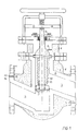
- the valve in Figure 1 is on via two flanges (1) Pipes can be connected to a pipe, their course thus continues along a channel (2), the Close the cross section with the plate (3) of the valve or is changeable.
- the actuation of the Plates (3) are made from the housing of the Valve led out spindle (4), which over a is movable at the end of its attached handwheel.
- the valve of two Surround walls (5, 6) which form a cavity (7) lock in.
- the cavity (7) is also included provided a connection (8) through which a measuring device to check its content, especially a Pressure gauge is connectable. Now becomes the inner one Wall (5) of the valve damaged, this occurs in the Channel (2) flowing medium not in the environment but in the cavity (7).
- the emerging Pressure change can be done with the one attached to the connection (8) Verify measuring device so that safety measures can be made and an exchange of the valve can take place before an exit through the outer wall (6) takes place.
- the cavity (7) with a medium other than air or with a pressure deviating from the outside air pressure, so can also be done by means of the measuring device Detect leaks in the outer wall (6).
- the implementation of mechanical actuators, in the example of the spindle (4) through the housing of the Valve requires a special fuse.
- the lower end of the spindle (4) is of a deformable bellows (10) surrounded, the tight with the plate (3) and the inner Wall (5) is connected. In this way it is created between bellows (10) and inner wall (5) the volume (11) of a further cavity the consequence that the medium located in channel (2) did not reach the bushing (4).
- the volume (11) can also be made using the bore (12) monitor through a measuring device to check for failure the bushings (9) or the bellows (10) to be able to.
- FIG. 2 shows a check valve according to the invention, where the names of similar components correspond to those in Figure 1.
- the plate (3) of the Valve is attached to a compression spring (16), which are supported on the inner wall (5) of the housing is.
- the liquid therefore flows from above down through the check valve, so located it is in the open state while the compression spring (16) with the opposite flow direction Presses plate (3) against its seat (17) and that The valve closes.
- Monitoring the cavity (7) takes place in this embodiment of the invention for example via a connection (8) that is in a component flanged to the flange (1) is located and through the holes (13) with the cavity (7) communicates.
- the groove (15), which the sealing surface (14) rotates, is in the seal (18) introduced.
Landscapes
- Engineering & Computer Science (AREA)
- General Engineering & Computer Science (AREA)
- Mechanical Engineering (AREA)
- Examining Or Testing Airtightness (AREA)
- Pipeline Systems (AREA)
- Materials For Medical Uses (AREA)
- Control Of Combustion (AREA)
- Pipe Accessories (AREA)
- Rigid Pipes And Flexible Pipes (AREA)
- Supports For Pipes And Cables (AREA)
- Details Of Valves (AREA)
- Indication Of The Valve Opening Or Closing Status (AREA)
- Glass Compositions (AREA)
- Check Valves (AREA)
- Duct Arrangements (AREA)
Description
- Fig. 1:
- Querschnitt durch ein erfindungsgemäßes Absperrventil,
- Fig. 2:
- Querschnitt durch ein erfindungsgemäßes Rückschlagventil.
Claims (11)
- Sicherheitsfunktionselement zur Beeinflussung oder Kontrolle fluider Medien in einer Leitung, insbesondere einer doppelwandigen Sicherheitsleitung, deren Wände durch einen Hohlraum voneinander beabstandet sind, wobei das Element mit einem von Wandungen (5) gebildeten Gehäuse versehen ist, wobei das Gehäuse allseitig von einer zweiten Wandung (6) umgeben ist, die von der ersten Wandung (5) durch einen Hohlraum (7) beabstandet ist und wobei in Betrieb der Hohlraum (7) gasdicht abgeschlossen ist, dadurch gekennzeichnet, daßdas Gehäuse Flansche (1) aufweist, durch die es dichtend mit der Leitung verbindbar ist,der Hohlraum mit einem Anschluß (8) versehen ist, über den ein Meßgerät zur Kontrolle seines Inhaltes verbindbar istund der Hohlraum (7) durch eine oder mehrere Bohrungen (13) mit einer Nut (15) verbunden ist, die in die Dichtfläche (14) des Flansches (1) oder seine Dichtung (18) eingebracht ist und in Betrieb die Leitung umläuft.
- Element nach Anspruch 1, dadurch gekennzeichnet, daß das Funktionselement eine Absperrvorrichtung ist.
- Element nach Anspruch 1, dadurch gekennzeichnet, daß das Funktionselement ein Rückschlagventil ist.
- Element nach einem der vorhergehenden Ansprüche, dadurch gekennzeichnet, daß das Funktionselement ein in das fluide Medium eingreifendes Wirkteil aufweist, das über ein mechanisches Koppelelement betätigbar ist, welches eine Durchführung im Gehäuse durchfaßt, und das Wirkteil durch einen Faltenbalg (10), der das fluide Medium von der Durchführung abteilt, mit dem Gehäuse verbunden ist.
- Element nach Anspruch 4, dadurch gekennzeichnet, daß das zwischen Faltenbalg (10) und Gehäuse eingeschlossene Volumen (11) mit einem Meßgerät zur Kontrolle seines Inhaltes verbindbar ist.
- Element nach einem der vorhergehenden Ansprüche, dadurch gekennzeichnet, daß das Funktionselement ein in das fluide Medium eingreifendes Wirkteil aufweist, das über ein mechanisches Koppelelement betätigbar ist, welches eine Durchführung im Gehäuse durchfaßt, und die Durchführung eine oder mehrere Buchsen (9) aufweist, die dichtend am Koppelelement anliegen.
- Element nach einem der vorhergehenden Ansprüche, dadurch gekennzeichnet, daß der Hohlraum (7) ein Vakuum, Druckgas oder ein Gas enthält.
- Element nach Anspruch 5, dadurch gekennzeichnet, daß das zwischen Faltenbalg (10) und Gehäuse eingeschlossene Volumen (11) ein Vakuum, Druckgas oder ein Gas enthält.
- Element nach einem der vorhergehenden Ansprüche, dadurch gekennzeichnet, daß die Nut (15) mit dem Hohlraum einer doppelwandigen Sicherheitsleitung über eine Öffnung in deren Flansch verbunden ist.
- Element nach Anspruch 9, dadurch gekennzeichnet, daß die Bohrung (13) zwischen Flansch (1) und Hohlraum (7) durch eine Sperrvorrichtung verschließbar ist.
- Element nach einem der vorhergehenden Ansprüche, dadurch gekennzeichnet, daß die Querschnittsfläche des Gehäuses dem äußeren Leitungsquerschnitt entspricht.
Applications Claiming Priority (3)
| Application Number | Priority Date | Filing Date | Title |
|---|---|---|---|
| DE19615472A DE19615472A1 (de) | 1996-04-19 | 1996-04-19 | Sicherheitsfunktionselement für eine Leitung |
| DE19615472 | 1996-04-19 | ||
| PCT/DE1997/000785 WO1997040304A1 (de) | 1996-04-19 | 1997-04-18 | Sicherheitsfunktionselement für eine leitung |
Publications (3)
| Publication Number | Publication Date |
|---|---|
| EP0892901A1 EP0892901A1 (de) | 1999-01-27 |
| EP0892901B1 true EP0892901B1 (de) | 2000-01-05 |
| EP0892901B2 EP0892901B2 (de) | 2003-02-05 |
Family
ID=7791733
Family Applications (1)
| Application Number | Title | Priority Date | Filing Date |
|---|---|---|---|
| EP97922853A Expired - Lifetime EP0892901B2 (de) | 1996-04-19 | 1997-04-18 | Sicherheitsfunktionselement für eine leitung |
Country Status (17)
| Country | Link |
|---|---|
| US (1) | US6178989B1 (de) |
| EP (1) | EP0892901B2 (de) |
| JP (1) | JP2000514159A (de) |
| CN (1) | CN1126891C (de) |
| AT (1) | ATE188541T1 (de) |
| AU (1) | AU2886497A (de) |
| BR (1) | BR9708766A (de) |
| CA (1) | CA2251774A1 (de) |
| CZ (1) | CZ292345B6 (de) |
| DE (2) | DE19615472A1 (de) |
| DK (1) | DK0892901T4 (de) |
| ES (1) | ES2145601T5 (de) |
| GR (1) | GR3033163T3 (de) |
| HU (1) | HU221077B1 (de) |
| PL (1) | PL183530B1 (de) |
| PT (1) | PT892901E (de) |
| WO (1) | WO1997040304A1 (de) |
Cited By (1)
| Publication number | Priority date | Publication date | Assignee | Title |
|---|---|---|---|---|
| EP1179505A1 (de) | 2000-08-08 | 2002-02-13 | Chemie- Und Tankanlagenbau Reuther Gmbh | Doppelwandiger Behälter mit Lekagedetektionseinrichtung |
Families Citing this family (15)
| Publication number | Priority date | Publication date | Assignee | Title |
|---|---|---|---|---|
| US7493911B2 (en) * | 2002-08-09 | 2009-02-24 | The Boeing Company | Shrouded valve apparatus and related methods |
| DE102004031574A1 (de) * | 2004-06-29 | 2006-02-09 | Daume Regelarmaturen Gmbh | Doppelwandiger Sicherheitstank mit Ventil |
| JP4981701B2 (ja) | 2007-01-30 | 2012-07-25 | 三星電子株式会社 | 端末機のタッチスクリーンを用いる文字入力装置及び方法 |
| KR100933398B1 (ko) | 2007-06-11 | 2009-12-22 | 삼성전자주식회사 | 터치 스크린을 구비한 단말기에서 입력 모드를 자동으로전환하는 문자 입력 장치 및 방법 |
| US8036837B2 (en) * | 2008-02-29 | 2011-10-11 | Fisher Controls International Llc | Diagnostic method for detecting control valve component failure |
| WO2009119919A1 (en) * | 2008-03-28 | 2009-10-01 | Mitsubishi Heavy Industries, Ltd. | Double pipe apparatus |
| JP5439269B2 (ja) * | 2010-02-01 | 2014-03-12 | 東洋自動機株式会社 | 液状物充填機の充填通路開閉装置 |
| CN101893130B (zh) * | 2010-07-05 | 2012-05-09 | 浙江万龙机械有限公司 | 一种波纹管密封组件及带有该波纹管密封组件的波纹管阀门 |
| FR3024179B1 (fr) * | 2014-07-25 | 2016-08-26 | Snecma | Systeme d'alimentation en air sous pression installe dans une turbomachine d'aeronef comportant des moyens d'etancheite |
| CN104585495A (zh) * | 2015-02-11 | 2015-05-06 | 郭庆 | 一种降低鸡蛋中胆固醇含量中药饲料添加剂的制备方法 |
| US10281053B2 (en) | 2015-10-12 | 2019-05-07 | Emerson Process Management Regulator Technologies, Inc. | Lattice structure valve/regulator body |
| JP6960261B2 (ja) * | 2017-06-30 | 2021-11-05 | 忠司 永田 | 配管保守支援機器及び配管保守支援システム |
| CN107387835A (zh) * | 2017-09-06 | 2017-11-24 | 简阳市中原低温设备配套有限公司 | 一种卡箍式连接低温截止阀 |
| CN108612851A (zh) * | 2018-06-25 | 2018-10-02 | 山东阿尔普尔节能装备有限公司 | 一种超低温螺杆机组用控制阀 |
| CN109442224B (zh) * | 2018-12-08 | 2020-09-25 | 台州鑫护家流体智控有限公司 | 一种燃气监控方法、系统及装置 |
Family Cites Families (28)
| Publication number | Priority date | Publication date | Assignee | Title |
|---|---|---|---|---|
| US2693822A (en) * | 1950-07-21 | 1954-11-09 | Cons Vacuum Corp | Piston operated valve with leak detection means |
| US2954797A (en) * | 1957-08-09 | 1960-10-04 | Eldon O Dryer | Leak control jacket apparatus |
| US2994337A (en) * | 1958-03-04 | 1961-08-01 | Robert R Freeman | Diapinch valve for hazardous materials |
| US3315700A (en) * | 1964-02-03 | 1967-04-25 | Eugene C Greenwood | Tubular jacketed double bellows valve |
| NL6716280A (de) | 1967-11-30 | 1969-06-03 | ||
| US3811649A (en) * | 1972-07-20 | 1974-05-21 | Resistoflex Corp | Constrictable tube valve with plural wall tube |
| US3964517A (en) * | 1975-01-14 | 1976-06-22 | Dickenson Harvard G | Four way diverter valve |
| US4158366A (en) * | 1977-07-27 | 1979-06-19 | Meter Chester J Van | Sillcock with water relief system |
| GB2047388B (en) * | 1979-04-24 | 1983-01-12 | Bvmi Ltd | Fluid-flow control valve |
| DE3175974D1 (en) * | 1980-11-07 | 1987-04-16 | David Baram | A valve |
| DE3138355A1 (de) † | 1981-09-26 | 1983-04-07 | kabelmetal electro GmbH, 3000 Hannover | Armatur fuer ein aus zwei metallrohren bestehendes leitungsrohr |
| DE3370524D1 (en) * | 1982-11-29 | 1987-04-30 | Bm Digiflow As | A stop or switch valve for fluids |
| GB2158558A (en) * | 1984-05-07 | 1985-11-13 | Smith International | High pressure valve having liner wear indicator |
| DE3516128A1 (de) * | 1985-05-04 | 1986-11-06 | Gea Ahlborn Gmbh & Co Kg, 3203 Sarstedt | Doppelsitzventil |
| EP0235314A1 (de) * | 1986-02-22 | 1987-09-09 | Ludwig Jacobs | Gehäuse für wärmeisolierte Armaturen und/oder Flanschverbindungen |
| DE3701027A1 (de) * | 1987-01-16 | 1988-07-28 | Hans Otto Mieth | Verfahren und vorrichtung zur steuerung eines leckageraumes eines ventils |
| DE8803960U1 (de) † | 1988-03-24 | 1988-05-11 | Ludwig, Klaus-Dieter, 7507 Pfinztal | Behälter zur Lagerung von Flüssigkeiten |
| DE3825575A1 (de) * | 1988-07-28 | 1990-02-08 | Schott Glaswerke | Absperrventil, insbesondere fuer gefaehrliche gase oder fluessigkeiten |
| US5056759A (en) * | 1990-09-12 | 1991-10-15 | Armstrong International, Inc. | Protected bellows for valve |
| US5203370A (en) * | 1991-11-26 | 1993-04-20 | Block Gary C | Mounting apparatus with fugitive emission collection means for directly coupling a rotary valve to an actuator having rotary drive means |
| US5228472A (en) * | 1992-03-16 | 1993-07-20 | Nippon Snaso Corporation | Valve unit for pipeline equipped with double flow tube |
| FR2698953B1 (fr) * | 1992-12-03 | 1995-01-06 | Snecma | Système de distribution de fluides à travers une enveloppe évidée et un couvercle à évent et dispositif de détection de fuites. |
| US5546977A (en) * | 1994-03-08 | 1996-08-20 | Conley Corporation | Dual containment valve system |
| US5615700A (en) * | 1994-03-08 | 1997-04-01 | Conley Corporation | Double containment fitting |
| FR2717550B1 (fr) | 1994-03-17 | 1996-06-07 | Europ Propulsion | Vanne cryogénique intégrale sous vide. |
| DE9416156U1 (de) * | 1994-10-07 | 1994-12-15 | Berrisch, Manfred, 78655 Dunningen | Zweibeiniger Fahrradständer mit integriertem Walzendynamo |
| DE19530058C2 (de) * | 1995-08-16 | 1999-04-01 | Walter Ludwig Behaelter Stahl | Behälter zur Lagerung von Flüssigkeiten |
| DE29602093U1 (de) * | 1996-02-07 | 1996-04-04 | Kapuschinski, Hubert, 63619 Bad Orb | Fangesack |
-
1996
- 1996-04-19 DE DE19615472A patent/DE19615472A1/de not_active Withdrawn
-
1997
- 1997-04-18 JP JP09537590A patent/JP2000514159A/ja active Pending
- 1997-04-18 AU AU28864/97A patent/AU2886497A/en not_active Abandoned
- 1997-04-18 CN CN97193885A patent/CN1126891C/zh not_active Expired - Fee Related
- 1997-04-18 DK DK97922853T patent/DK0892901T4/da active
- 1997-04-18 DE DE59700979T patent/DE59700979D1/de not_active Expired - Lifetime
- 1997-04-18 PT PT97922853T patent/PT892901E/pt unknown
- 1997-04-18 CZ CZ19983297A patent/CZ292345B6/cs not_active IP Right Cessation
- 1997-04-18 BR BR9708766-1A patent/BR9708766A/pt active Search and Examination
- 1997-04-18 PL PL97329354A patent/PL183530B1/pl not_active IP Right Cessation
- 1997-04-18 CA CA002251774A patent/CA2251774A1/en not_active Abandoned
- 1997-04-18 HU HU9901520A patent/HU221077B1/hu not_active IP Right Cessation
- 1997-04-18 AT AT97922853T patent/ATE188541T1/de not_active IP Right Cessation
- 1997-04-18 ES ES97922853T patent/ES2145601T5/es not_active Expired - Lifetime
- 1997-04-18 EP EP97922853A patent/EP0892901B2/de not_active Expired - Lifetime
- 1997-04-18 US US09/171,556 patent/US6178989B1/en not_active Expired - Fee Related
- 1997-04-18 WO PCT/DE1997/000785 patent/WO1997040304A1/de active IP Right Grant
-
2000
- 2000-04-05 GR GR20000400856T patent/GR3033163T3/el not_active IP Right Cessation
Cited By (1)
| Publication number | Priority date | Publication date | Assignee | Title |
|---|---|---|---|---|
| EP1179505A1 (de) | 2000-08-08 | 2002-02-13 | Chemie- Und Tankanlagenbau Reuther Gmbh | Doppelwandiger Behälter mit Lekagedetektionseinrichtung |
Also Published As
| Publication number | Publication date |
|---|---|
| HU221077B1 (hu) | 2002-07-29 |
| ES2145601T5 (es) | 2003-10-16 |
| PL329354A1 (en) | 1999-03-29 |
| DK0892901T4 (da) | 2003-12-15 |
| BR9708766A (pt) | 2000-01-04 |
| DK0892901T3 (da) | 2000-06-26 |
| HUP9901520A1 (hu) | 1999-08-30 |
| GR3033163T3 (en) | 2000-08-31 |
| HUP9901520A3 (en) | 2001-07-30 |
| WO1997040304A1 (de) | 1997-10-30 |
| DE59700979D1 (de) | 2000-02-10 |
| PT892901E (pt) | 2000-06-30 |
| CA2251774A1 (en) | 1997-10-30 |
| ES2145601T3 (es) | 2000-07-01 |
| CZ9803297A3 (cs) | 2001-01-17 |
| CN1216602A (zh) | 1999-05-12 |
| EP0892901A1 (de) | 1999-01-27 |
| EP0892901B2 (de) | 2003-02-05 |
| PL183530B1 (pl) | 2002-06-28 |
| CZ292345B6 (cs) | 2003-09-17 |
| AU2886497A (en) | 1997-11-12 |
| DE19615472A1 (de) | 1997-10-23 |
| ATE188541T1 (de) | 2000-01-15 |
| CN1126891C (zh) | 2003-11-05 |
| US6178989B1 (en) | 2001-01-30 |
| JP2000514159A (ja) | 2000-10-24 |
Similar Documents
| Publication | Publication Date | Title |
|---|---|---|
| EP0892901B1 (de) | Sicherheitsfunktionselement für eine leitung | |
| DE60224978T2 (de) | Vorrichtung und verfahren zur online-erkennung von leckenden ventilen | |
| EP0507127B1 (de) | Rohrweiche | |
| EP0833090A1 (de) | Kugelhahn | |
| EP0758619B1 (de) | Behälter zur Lagerung von Flüssigkeiten | |
| DE4021369C1 (de) | ||
| EP2100063A1 (de) | Gassicherheitsventil mit gasdetektor | |
| EP1179505B1 (de) | Doppelwandiger Behälter mit Lekagedetektionseinrichtung | |
| DE3819300C1 (en) | Method for testing the leak-tightness of sealing elements in shut-off fittings and a device for carrying out the method | |
| DE19610151C1 (de) | Lagestabiler Axial-Kompensator | |
| EP0772477B1 (de) | Vorrichtung zum automatischen schliessen einer absperrarmatur | |
| DE9404829U1 (de) | Armatur | |
| DE3937778C2 (de) | Alarmventilstation | |
| DE2546496C3 (de) | Absperrarmatur für zweisträngige Rohrleitungen | |
| EP1792112A1 (de) | Ventil und doppelwandiger sicherheitstank mit diesem ventil | |
| DE3333234A1 (de) | Schlauchbruchsicherung mit leckgasueberpruefungseinrichtung | |
| DE202016102625U1 (de) | Sicherheitsablassventil für Lastkraftwagen-Tanker | |
| DE3706590C2 (de) | Vorrichtung zum zeitweiligen Verschließen des Querschnittes einer Gas oder Flüssigkeit führenden Rohrleitung | |
| DD267541A5 (de) | Schnellschluss-absperrschieber | |
| DE4318872A1 (de) | Doppelrohr für eine pneumatische Förderung | |
| EP0581207B1 (de) | Messeinrichtung zur Erfassung der Gasbeladung oder Dampfdruckes einer Flüssigkeit, insbesondere einer fliessfähigen Kunststoffkomponente | |
| EP2018500B1 (de) | Vorrichtung zum entlüften oder belüften oder entleeren eines rohrleitungsnetzes | |
| DE9311830U1 (de) | Kugelhahn zum Einbau in Gas- und Flüssigkeitsleitungen, mit einer Vorrichtung zum Überprüfen der Funktionsfähigkeit der Dichtungen | |
| DE4121175C1 (de) | ||
| DE3628192A1 (de) | In eine rohrleitung einfuegbare schnellschlusseinrichtung |
Legal Events
| Date | Code | Title | Description |
|---|---|---|---|
| PUAI | Public reference made under article 153(3) epc to a published international application that has entered the european phase |
Free format text: ORIGINAL CODE: 0009012 |
|
| 17P | Request for examination filed |
Effective date: 19981119 |
|
| AK | Designated contracting states |
Kind code of ref document: A1 Designated state(s): AT BE CH DE DK ES FI FR GB GR IE IT LI LU MC NL PT SE |
|
| GRAG | Despatch of communication of intention to grant |
Free format text: ORIGINAL CODE: EPIDOS AGRA |
|
| GRAG | Despatch of communication of intention to grant |
Free format text: ORIGINAL CODE: EPIDOS AGRA |
|
| GRAH | Despatch of communication of intention to grant a patent |
Free format text: ORIGINAL CODE: EPIDOS IGRA |
|
| 17Q | First examination report despatched |
Effective date: 19990518 |
|
| GRAH | Despatch of communication of intention to grant a patent |
Free format text: ORIGINAL CODE: EPIDOS IGRA |
|
| GRAA | (expected) grant |
Free format text: ORIGINAL CODE: 0009210 |
|
| AK | Designated contracting states |
Kind code of ref document: B1 Designated state(s): AT BE CH DE DK ES FI FR GB GR IE IT LI LU MC NL PT SE |
|
| REF | Corresponds to: |
Ref document number: 188541 Country of ref document: AT Date of ref document: 20000115 Kind code of ref document: T |
|
| REG | Reference to a national code |
Ref country code: CH Ref legal event code: EP |
|
| REF | Corresponds to: |
Ref document number: 59700979 Country of ref document: DE Date of ref document: 20000210 |
|
| REG | Reference to a national code |
Ref country code: IE Ref legal event code: FG4D Free format text: GERMAN |
|
| ET | Fr: translation filed | ||
| ITF | It: translation for a ep patent filed |
Owner name: NUCCI ANNA MARIA |
|
| GBT | Gb: translation of ep patent filed (gb section 77(6)(a)/1977) |
Effective date: 20000228 |
|
| PG25 | Lapsed in a contracting state [announced via postgrant information from national office to epo] |
Ref country code: LU Free format text: LAPSE BECAUSE OF NON-PAYMENT OF DUE FEES Effective date: 20000418 |
|
| REG | Reference to a national code |
Ref country code: DK Ref legal event code: T3 |
|
| REG | Reference to a national code |
Ref country code: PT Ref legal event code: SC4A Free format text: AVAILABILITY OF NATIONAL TRANSLATION Effective date: 20000405 |
|
| REG | Reference to a national code |
Ref country code: ES Ref legal event code: FG2A Ref document number: 2145601 Country of ref document: ES Kind code of ref document: T3 |
|
| PLBQ | Unpublished change to opponent data |
Free format text: ORIGINAL CODE: EPIDOS OPPO |
|
| PLBI | Opposition filed |
Free format text: ORIGINAL CODE: 0009260 |
|
| PG25 | Lapsed in a contracting state [announced via postgrant information from national office to epo] |
Ref country code: MC Free format text: LAPSE BECAUSE OF NON-PAYMENT OF DUE FEES Effective date: 20001031 |
|
| PLBF | Reply of patent proprietor to notice(s) of opposition |
Free format text: ORIGINAL CODE: EPIDOS OBSO |
|
| 26 | Opposition filed |
Opponent name: WALTER LUDWIG BEHAELTER-UND ANLAGEBAU Effective date: 20000929 |
|
| NLR1 | Nl: opposition has been filed with the epo |
Opponent name: WALTER LUDWIG BEHAELTER-UND ANLAGEBAU |
|
| PLBF | Reply of patent proprietor to notice(s) of opposition |
Free format text: ORIGINAL CODE: EPIDOS OBSO |
|
| PLBF | Reply of patent proprietor to notice(s) of opposition |
Free format text: ORIGINAL CODE: EPIDOS OBSO |
|
| REG | Reference to a national code |
Ref country code: GB Ref legal event code: 732E |
|
| REG | Reference to a national code |
Ref country code: GB Ref legal event code: IF02 |
|
| PGFP | Annual fee paid to national office [announced via postgrant information from national office to epo] |
Ref country code: GB Payment date: 20020410 Year of fee payment: 6 |
|
| PGFP | Annual fee paid to national office [announced via postgrant information from national office to epo] |
Ref country code: FR Payment date: 20020416 Year of fee payment: 6 |
|
| PGFP | Annual fee paid to national office [announced via postgrant information from national office to epo] |
Ref country code: AT Payment date: 20020419 Year of fee payment: 6 |
|
| PGFP | Annual fee paid to national office [announced via postgrant information from national office to epo] |
Ref country code: SE Payment date: 20020422 Year of fee payment: 6 Ref country code: FI Payment date: 20020422 Year of fee payment: 6 |
|
| PGFP | Annual fee paid to national office [announced via postgrant information from national office to epo] |
Ref country code: ES Payment date: 20020424 Year of fee payment: 6 |
|
| PGFP | Annual fee paid to national office [announced via postgrant information from national office to epo] |
Ref country code: GR Payment date: 20020426 Year of fee payment: 6 |
|
| PGFP | Annual fee paid to national office [announced via postgrant information from national office to epo] |
Ref country code: PT Payment date: 20020429 Year of fee payment: 6 Ref country code: IE Payment date: 20020429 Year of fee payment: 6 |
|
| PLAW | Interlocutory decision in opposition |
Free format text: ORIGINAL CODE: EPIDOS IDOP |
|
| PLAW | Interlocutory decision in opposition |
Free format text: ORIGINAL CODE: EPIDOS IDOP |
|
| PUAH | Patent maintained in amended form |
Free format text: ORIGINAL CODE: 0009272 |
|
| STAA | Information on the status of an ep patent application or granted ep patent |
Free format text: STATUS: PATENT MAINTAINED AS AMENDED |
|
| 27A | Patent maintained in amended form |
Effective date: 20030205 |
|
| AK | Designated contracting states |
Designated state(s): AT BE CH DE DK ES FI FR GB GR IE IT LI LU MC NL PT SE |
|
| REG | Reference to a national code |
Ref country code: CH Ref legal event code: AEN Free format text: AUFRECHTERHALTUNG DES PATENTES IN GEAENDERTER FORM |
|
| NLR2 | Nl: decision of opposition |
Effective date: 20030205 |
|
| REG | Reference to a national code |
Ref country code: SE Ref legal event code: RPEO |
|
| PG25 | Lapsed in a contracting state [announced via postgrant information from national office to epo] |
Ref country code: IE Free format text: LAPSE BECAUSE OF NON-PAYMENT OF DUE FEES Effective date: 20030418 Ref country code: GB Free format text: LAPSE BECAUSE OF NON-PAYMENT OF DUE FEES Effective date: 20030418 Ref country code: FI Free format text: LAPSE BECAUSE OF NON-PAYMENT OF DUE FEES Effective date: 20030418 Ref country code: AT Free format text: LAPSE BECAUSE OF NON-PAYMENT OF DUE FEES Effective date: 20030418 |
|
| PG25 | Lapsed in a contracting state [announced via postgrant information from national office to epo] |
Ref country code: SE Free format text: LAPSE BECAUSE OF NON-PAYMENT OF DUE FEES Effective date: 20030419 Ref country code: ES Free format text: LAPSE BECAUSE OF NON-PAYMENT OF DUE FEES Effective date: 20030419 |
|
| GBTA | Gb: translation of amended ep patent filed (gb section 77(6)(b)/1977) | ||
| PG25 | Lapsed in a contracting state [announced via postgrant information from national office to epo] |
Ref country code: GR Free format text: THE PATENT HAS BEEN ANNULLED BY A DECISION OF A NATIONAL AUTHORITY Effective date: 20030609 |
|
| NLR3 | Nl: receipt of modified translations in the netherlands language after an opposition procedure | ||
| ET3 | Fr: translation filed ** decision concerning opposition | ||
| REG | Reference to a national code |
Ref country code: ES Ref legal event code: DC2A Date of ref document: 20030429 Kind code of ref document: T5 |
|
| PG25 | Lapsed in a contracting state [announced via postgrant information from national office to epo] |
Ref country code: PT Free format text: LAPSE BECAUSE OF NON-PAYMENT OF DUE FEES Effective date: 20031031 |
|
| EUG | Se: european patent has lapsed | ||
| REG | Reference to a national code |
Ref country code: DK Ref legal event code: EGE |
|
| GBPC | Gb: european patent ceased through non-payment of renewal fee |
Effective date: 20030418 |
|
| REG | Reference to a national code |
Ref country code: DK Ref legal event code: T4 |
|
| PG25 | Lapsed in a contracting state [announced via postgrant information from national office to epo] |
Ref country code: FR Free format text: LAPSE BECAUSE OF NON-PAYMENT OF DUE FEES Effective date: 20031231 |
|
| REG | Reference to a national code |
Ref country code: FR Ref legal event code: ST Ref country code: PT Ref legal event code: MM4A Free format text: LAPSE DUE TO NON-PAYMENT OF FEES Effective date: 20031031 |
|
| REG | Reference to a national code |
Ref country code: IE Ref legal event code: MM4A |
|
| BECA | Be: change of holder's address |
Owner name: AM SONNENHANG 11, 35415 POHLHEIM (DE) Effective date: 20040730 Owner name: JATHOSTRASSE 8, D-30916 ISERNHAGEN (DE) Effective date: 20040730 Owner name: *KOLB HANNELOREHAINERWEG 248, 60599 FRANKFURT Effective date: 20040730 Owner name: *DAUME REGELARMATUREN G.M.B.H. Effective date: 20040730 Owner name: *WINDSCHMITT HANS Effective date: 20040730 |
|
| REG | Reference to a national code |
Ref country code: ES Ref legal event code: FD2A Effective date: 20030419 |
|
| NLS | Nl: assignments of ep-patents |
Owner name: HANS WINDSCHMITT Owner name: HANNELORE KOLB Owner name: DAUME REGELARMATUREN GMBH |
|
| PG25 | Lapsed in a contracting state [announced via postgrant information from national office to epo] |
Ref country code: IT Free format text: LAPSE BECAUSE OF NON-PAYMENT OF DUE FEES;WARNING: LAPSES OF ITALIAN PATENTS WITH EFFECTIVE DATE BEFORE 2007 MAY HAVE OCCURRED AT ANY TIME BEFORE 2007. THE CORRECT EFFECTIVE DATE MAY BE DIFFERENT FROM THE ONE RECORDED. Effective date: 20050418 |
|
| PGFP | Annual fee paid to national office [announced via postgrant information from national office to epo] |
Ref country code: DK Payment date: 20050426 Year of fee payment: 9 |
|
| PG25 | Lapsed in a contracting state [announced via postgrant information from national office to epo] |
Ref country code: DK Free format text: LAPSE BECAUSE OF NON-PAYMENT OF DUE FEES Effective date: 20060501 |
|
| REG | Reference to a national code |
Ref country code: DK Ref legal event code: EBP |
|
| PLAB | Opposition data, opponent's data or that of the opponent's representative modified |
Free format text: ORIGINAL CODE: 0009299OPPO |
|
| PGFP | Annual fee paid to national office [announced via postgrant information from national office to epo] |
Ref country code: CH Payment date: 20110426 Year of fee payment: 15 |
|
| PGFP | Annual fee paid to national office [announced via postgrant information from national office to epo] |
Ref country code: NL Payment date: 20110503 Year of fee payment: 15 Ref country code: BE Payment date: 20110525 Year of fee payment: 15 |
|
| REG | Reference to a national code |
Ref country code: DE Ref legal event code: R082 Ref document number: 59700979 Country of ref document: DE Representative=s name: WAGNER, DR. HERRGUTH PATENTANWAELTE, DE Effective date: 20110922 Ref country code: DE Ref legal event code: R082 Ref document number: 59700979 Country of ref document: DE Representative=s name: PATENTANWAELTE WAGNER DR. HERRGUTH, DE Effective date: 20110922 Ref country code: DE Ref legal event code: R081 Ref document number: 59700979 Country of ref document: DE Owner name: DAUME, BRITTA, DE Free format text: FORMER OWNERS: DAUME, BRITTA, 30938 BURGWEDEL, DE; KOLB, GEORG, 63814 MAINASCHAFF, DE; WINDSCHMITT, HANS, 60599 FRANKFURT, DE Effective date: 20110922 Ref country code: DE Ref legal event code: R081 Ref document number: 59700979 Country of ref document: DE Owner name: KOLB, GEORG, DE Free format text: FORMER OWNERS: DAUME, BRITTA, 30938 BURGWEDEL, DE; KOLB, GEORG, 63814 MAINASCHAFF, DE; WINDSCHMITT, HANS, 60599 FRANKFURT, DE Effective date: 20110922 Ref country code: DE Ref legal event code: R081 Ref document number: 59700979 Country of ref document: DE Owner name: WINDSCHMITT, HANS, DE Free format text: FORMER OWNERS: DAUME, BRITTA, 30938 BURGWEDEL, DE; KOLB, GEORG, 63814 MAINASCHAFF, DE; WINDSCHMITT, HANS, 60599 FRANKFURT, DE Effective date: 20110922 Ref country code: DE Ref legal event code: R081 Ref document number: 59700979 Country of ref document: DE Owner name: DAUME, BRITTA, DE Free format text: FORMER OWNER: BRITTA DAUME,GEORG KOLB,HANS WINDSCHMITT, , DE Effective date: 20110922 Ref country code: DE Ref legal event code: R081 Ref document number: 59700979 Country of ref document: DE Owner name: KOLB, GEORG, DE Free format text: FORMER OWNER: BRITTA DAUME,GEORG KOLB,HANS WINDSCHMITT, , DE Effective date: 20110922 Ref country code: DE Ref legal event code: R081 Ref document number: 59700979 Country of ref document: DE Owner name: WINDSCHMITT, HANS, DE Free format text: FORMER OWNER: BRITTA DAUME,GEORG KOLB,HANS WINDSCHMITT, , DE Effective date: 20110922 |
|
| BERE | Be: lapsed |
Owner name: *WINDSCHMITT HANS Effective date: 20120430 Owner name: *KOLB HANNELORE Effective date: 20120430 Owner name: *DAUME REGELARMATUREN G.M.B.H. Effective date: 20120430 |
|
| REG | Reference to a national code |
Ref country code: NL Ref legal event code: V1 Effective date: 20121101 |
|
| REG | Reference to a national code |
Ref country code: CH Ref legal event code: PL |
|
| PG25 | Lapsed in a contracting state [announced via postgrant information from national office to epo] |
Ref country code: LI Free format text: LAPSE BECAUSE OF NON-PAYMENT OF DUE FEES Effective date: 20120430 Ref country code: BE Free format text: LAPSE BECAUSE OF NON-PAYMENT OF DUE FEES Effective date: 20120430 Ref country code: CH Free format text: LAPSE BECAUSE OF NON-PAYMENT OF DUE FEES Effective date: 20120430 |
|
| PG25 | Lapsed in a contracting state [announced via postgrant information from national office to epo] |
Ref country code: NL Free format text: LAPSE BECAUSE OF NON-PAYMENT OF DUE FEES Effective date: 20121101 |
|
| PGFP | Annual fee paid to national office [announced via postgrant information from national office to epo] |
Ref country code: DE Payment date: 20130430 Year of fee payment: 17 |
|
| REG | Reference to a national code |
Ref country code: DE Ref legal event code: R119 Ref document number: 59700979 Country of ref document: DE |
|
| PG25 | Lapsed in a contracting state [announced via postgrant information from national office to epo] |
Ref country code: DE Free format text: LAPSE BECAUSE OF NON-PAYMENT OF DUE FEES Effective date: 20141101 |
|
| REG | Reference to a national code |
Ref country code: DE Ref legal event code: R119 Ref document number: 59700979 Country of ref document: DE Effective date: 20141101 |