EP0892420A2 - Verklinkungsmechanismus für einen elektrischen Ueberstromschutzschalter insbesondere für einen Motorschutzschalter - Google Patents
Verklinkungsmechanismus für einen elektrischen Ueberstromschutzschalter insbesondere für einen Motorschutzschalter Download PDFInfo
- Publication number
- EP0892420A2 EP0892420A2 EP97121795A EP97121795A EP0892420A2 EP 0892420 A2 EP0892420 A2 EP 0892420A2 EP 97121795 A EP97121795 A EP 97121795A EP 97121795 A EP97121795 A EP 97121795A EP 0892420 A2 EP0892420 A2 EP 0892420A2
- Authority
- EP
- European Patent Office
- Prior art keywords
- slide
- main
- spring
- switch
- signaling
- Prior art date
- Legal status (The legal status is an assumption and is not a legal conclusion. Google has not performed a legal analysis and makes no representation as to the accuracy of the status listed.)
- Granted
Links
Images


Classifications
-
- H—ELECTRICITY
- H01—ELECTRIC ELEMENTS
- H01H—ELECTRIC SWITCHES; RELAYS; SELECTORS; EMERGENCY PROTECTIVE DEVICES
- H01H71/00—Details of the protective switches or relays covered by groups H01H73/00 - H01H83/00
- H01H71/10—Operating or release mechanisms
- H01H71/50—Manual reset mechanisms which may be also used for manual release
- H01H71/56—Manual reset mechanisms which may be also used for manual release actuated by rotatable knob or wheel
-
- H—ELECTRICITY
- H01—ELECTRIC ELEMENTS
- H01H—ELECTRIC SWITCHES; RELAYS; SELECTORS; EMERGENCY PROTECTIVE DEVICES
- H01H71/00—Details of the protective switches or relays covered by groups H01H73/00 - H01H83/00
- H01H71/10—Operating or release mechanisms
- H01H71/12—Automatic release mechanisms with or without manual release
- H01H71/46—Automatic release mechanisms with or without manual release having means for operating auxiliary contacts additional to the main contacts
- H01H71/462—Automatic release mechanisms with or without manual release having means for operating auxiliary contacts additional to the main contacts housed in a separate casing, juxtaposed to and having the same general contour as the main casing
Definitions
- the present invention relates to a latch mechanism for a electrical overcurrent protection switch, in particular for a motor protection switch with a toggle lever, by a manual operating device tensionable switch lock, with a triggerable by an overcurrent, the triggered position of the switching lock effecting release pawl, the Manual control device is latched in the released position and with Means for the transmission of a trip message to an auxiliary switch.
- EP-B1-0612089 describes a switching device for power switching devices known.
- the main actuators of the switching device consist of a manual override that is operatively connected to a key switch stands and from a toggle lever by the manual override cocked and either by the manual control device itself or by thermal or magnetic release devices triggered by buckling can be.
- this switching device there are means for transmitting a Tripped message provided on an auxiliary switch.
- the one for the manual control device The provided return spring acts on the toggle lever and thus influences the triggering forces of the switching device. Because this return spring is on acts on the toggle lever, the greater restoring force cannot be achieved without special measures.
- the Assembly of this switching device is due to the many articulations, in particular with a fully automated assembly also difficult.
- the object of the present invention is an economically advantageous To develop latching mechanism of the type mentioned at the beginning, the consists of a few parts, is easy to assemble and in which the on Manual operating device resetting force according to the given needs can be adjusted.
- the task is solved in that one with perpendicular to each other fixed guide provided with aligned guide elements is provided, on which a form-fittingly connected to the manual operating device OFF, ON and tripped positions in the switch-off direction of the Manual control device by a main spring spring-loaded main slide is guided and in the chamber perpendicular to the direction of displacement of the Main slide in the direction away from the main slide by a Signaling slide spring with spring-loaded ON, OFF and tripped positions longitudinally displaceable signal slide is performed and in which Part of the chamber facing away from the main slide in the on position of the Overcurrent protection switch the hinge point of the knee lever of the key switch supportive, towards the joint of the knee lever by means of a spring lever spring-loaded spring lever is pivotally mounted, with a switch-on movement of the overcurrent protection switch of the signaling slide via interacting Sloping surfaces on the main slide and on the signal slide against the effect the signal slide spring moved by the main slide and behind one additional switch-off bevels on the main slide are locked, the main slider supports
- This latching mechanism consists of relatively few parts and is also easy to install in a fully automated assembly. Because the Main slide in the on position of the overcurrent protection switch on the signal slide is locked, the main spring only acts on the main slide and influences the toggle lever and thereby the triggering forces of the overcurrent protection switch Not.
- the main slide can be box-shaped and the main spring box-shaped Cavity to be housed, with the helical main spring one end of the box wall and the other End at a fixed stop protruding into the cavity of the main slide supports.
- this measure allows space-saving accommodation the main spring and on the other hand that the main spring only on the Main slide works.
- the main slide advantageously has a positive connection the rack serving the manual control device.
- the rack allows a simple, positive connection between the corresponding Gear-carrying manual control device and the main slide.
- the signaling slide advantageously has a protruding from the chamber release nose provided for the attack by the release pawl. This simple arrangement is particularly suitable for fully automatic assembly.
- the signaling slide can be one protruding from the chamber for the transmission a triggered message on an auxiliary switch certain reporting nose exhibit.
- the signaling nose enables simple connection of auxiliary switching elements to the triggered message.
- the indicator slide advantageously has one of two elastically resilient jaws existing snap on which is in the latched position of the latching mechanism releasably latched to a detent formed on the chamber. This simple arrangement enables the latching mechanism to be locked securely in the tripped position.
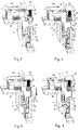
- the two Figures 1 and 2 show in exploded views from different Angles of the components of a latching mechanism.
- This Latch mechanism is for an electrical overcurrent breaker, especially provided for a motor protection switch.
- the one in the drawings not shown, for example from Swiss patent application no 00307/96 dated February 6, 1996 by the same applicant known overcurrent protection switch has a key switch with a toggle lever, the key switch can be tensioned by a manual operating device.
- the overcurrent protection switch is equipped with a release pawl, which is caused by an overcurrent can be triggered and also via the latch mechanism on the key switch works.
- the latch mechanism latches the manual control device in the triggered position and actuates the for the transmission of the triggered message means provided on an auxiliary switch, which is usually contains a lever or pestle.
- a stationary chamber 1 shown in FIGS. 1 and 2 is connected to one another vertically aligned guide elements.
- chamber 1 In chamber 1 is a main slide 2 and perpendicular to a signaling slide 3 out.
- a jump lever 4 is used with the help of a Bolt 5 pivotally mounted.
- the main slide 2 is provided with a slot 6, in which one at the Chamber 1 integrally formed comb 47 engages.
- the main slide 2 carries on the side a rack 10 which for a positive connection with a gear provided, not shown manual control device is determined.
- the main slide 2 is is box-shaped and has a cavity 11. In this cavity 11, a helical main spring 12 is inserted.
- the main spring 12 in the assembled state is supported with one end on the box wall 13 and with its other end at one into the cavity 11 of the main slide 2 protruding, molded on the chamber 1 stop 14.
- the main slide has an inclined extension at its end area facing the signaling slide 3 15 on. As will be explained later, determines the angular position of the Run-up slope 16 of this inclined extension 15 the position of the manual drive device in the tripped position.
- a control lug 17 on the main slide 2 determines with their switch-off slope 18 the switch-off torque and with their Switch-on slope 19, the switch-on torque of the overcurrent protection switch as it will be explained later.
- the main slide 2 also has an areal Anchor arm support 20 on the support surface 21 of the ankle lever 4 supports in the ON position of the overcurrent protection switch.
- the indicator slide 3 is with its rib 22 in the slot 23 of the chamber 1 guided.
- the signaling slide 3 is through the signaling slide spring 24 in the Chamber 1 pressed in.
- the signal slide spring 24 is supported on the top only indicated by a small cutout housing 25 and at the bottom of an Detector slide 3 molded pins 26 from.
- the indicator slide 3 has a assembled state protruding from chamber 1, for attack by the Trigger pawl provided on trigger nose 27.
- One is on signaling slide 3 the switch-off bevel 18 on the main slide 2 cooperating switch-off bevel surface 28 molded. At the rear of this switch-off inclined surface 28 there is another, cooperating with the switch-on slope 19 Slant 43, which is only visible in Figures 4 and 11.
- the alarm slide 3 is with a protruding nose protruding from the chamber 1 in the assembled state 30 provided.
- the alarm slide 3 has one of two elastically resilient Bake 31, 32 existing snappers. In the latched position of the Locking mechanism lock these jaws 31, 32 with one on the Chamber 1 molded detent 33 releasable. Lie in the locked position the jaws 31, 32 on both sides of the latch plate 34.
- the jump lever 4 is in the lower part of the chamber 1 with the help of the bolt 5 pivoted.
- a nose 35 is in the assembled state of the Chamber 1 in front and supports in the on position in the overcurrent protection switch the knee joint of the key switch.
- the lever 4 is under the Effect of the spring lever 36, which is at one end on the pin 37th the jump lever 4 and with its other end on the housing, not shown supports.
- the spring lever 36 ensures that when switching on Support surface 21 of the jump lever 4 on the jump lever support 20 on the main slide 2 comes to rest.
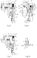
- FIGS. 3 to 14 The functioning of the latching mechanism is illustrated in FIGS. 3 to 14 described in more detail.
- FIG. 3 shows the latching mechanism at the start of a switch-on movement from the off position.
- the main slide 2 is not with the shown manual operating device on the rack 10 in the direction of the arrow 38 pushed.
- the main spring 12 housed in the main slide 2 becomes thereby gasping.
- the alarm slide 3 from the flat switch-on bevel 19 upwards, moving in the direction of arrow 39 and the Indicator slide spring 24 tensioned, as shown in Fig.4.
- the alarm slide 3 After exceeding the The highest point of the switch-on slope 19 is the alarm slide 3, as from Fig.5 emerges from the signal slide spring 24 back to its rest position deferred.
- the main slide 2 also reaches with the Rack 10 its end position. Due to the steep switch-off inclined surface 28 the slide valve 3, the main slide 2 remains in this position when released the manual control device.
- the latch mechanism is engaged, as shown in Fig. 5 in the on position.
- the manual control device When switching off, the manual control device is in the opposite Direction actuated.
- the main slide 2 is in the direction of arrow 40 in FIG. 6 emotional.
- an increased force must be exerted on the manual control device be applied because the steep switch-off slope 18th of the main slide 2, the signaling slide 3 in the direction of arrow 41 from the latching must press.
- the entire latching mechanism After exceeding the highest point of the switch-off slope 18, the entire latching mechanism returns, even when you release the Manual operation, in its starting position, in the switch-off position.
- the force for the resetting is released after the locking of the main spring 12 applied.
- the switch-off position is shown in Fig. 7.
- the manual control device When the latching mechanism is reset from the released position the manual control device must be operated in the OFF direction, such as Fig.13 it shows. At the beginning of this movement an increased force must be applied manually be applied to release the released latching. This happens through the ramp 16 on the main slide 2 as Fig.13 it shows.
- the ramp 16 presses the signaling slide 3 over the counter bevels 29 below from his with the two jaws 31, 32 and with the latch 33 caused locking out. After releasing the latching slide 3 it returns to its rest position on the action of the signal slide spring 24.
- the latching mechanism and any auxiliary switching elements are reversing, as already described when switching off, automatically return to their rest positions. In this way, the latching mechanism reaches that shown in Fig. 14 OFF position.
Abstract
Description
Claims (6)
- Verklinkungsmechanismus für einen elektrischen Ueberstromschutzschalter, insbesondere für einen Motorschutzschalter mit einem einen Kniehebel aufweisenden, durch eine Handbetätigungsvorrichtung spannbaren Schaltschloss, mit einer durch einen Ueberstrom auslösbaren, die Ausgelöst-Stellung des Schaltschlosses bewirkenden Auslöseklinke, wobei die Handbetätigungsvorrichtung in der Ausgelöst-Stellung verklinkt ist und mit Mitteln für die Uebertragung einer Ausgelöst-Meldung auf einen Hilfsschalter, dadurch gekennzeichnet, dass eine mit zueinander senkrecht ausgerichteten Führungselementen versehene, ortsfeste Kammer (1) vorgesehen ist, auf welcher ein mit der Handbetätigungsvorrichtung formschlüssig verbundener, AUS-, EIN- und Ausgelöst-Stellungen aufweisender in Ausschaltrichtung der Handbetätigungsvorrichtung durch eine Hauptfeder (12) federbelasteter Hauptschieber (2) geführt ist und in der Kammer (1) senkrecht zur Verschieberichtung des Hauptschiebers (2) ein in der dem Hauptschieber (2) abgekehrten Richtung durch eine Meldeschieberfeder (24) Lederbelasteter EIN-, AUS- und Ausgelöst-Stellungen aufweisender, längsverschiebbarer Meldeschieber (3) geführt ist und in dem dem Hauptschieber (2) abgekehrten Teil der Kammer (1) ein in der Einschaltstellung des Ueberstromschutzschalters die Gelenkstelle des Kniehebels des Schaltschlosses stützender, zur Gelenkstelle des Kniehebels hin durch eine Sprunghebelfeder (36) federbelasteter Sprunghebel (4) schwenkbar gelagert ist, wobei bei einer Einschaltbewegung des Ueberstromschutzschalters der Meldeschieber (3) über zusammenwirkende Schrägflächen (19, 28) am Hauptschieber (2) und am Meldeschieber (3) gegen die Wirkung der Meldeschieberfeder (24) durch den Hauptschieber (2) verschoben und hinter einer weiteren, auf dem Hauptschieber (2) vorhandene Ausschaltschräge (18) verrastet wird, wobei der Hauptschieber (2) den Sprunghebel (4) stützt, bei einer Ausschaltbewegung des Ueberstromschutzschalters die Ausschaltschräge (18) auf dem Hauptschieber (2) den Meldeschieber (3) gegen die Wirkung der Meldeschieberfeder (24) verschiebt, entrastet, so dass der Hauptschieber (2) auf Wirkung der Hauptfeder (12) in die AUS-Stellung fährt und die Sprunghebelabstützung (20) aufhebt, bei einer Auslösung des Ueberstromschutzschalters durch einen Ueberstrom die Auslöseklinke des Ueberstromschutzschalters den Meldeschieber (3) gegen die Wirkung der Meldeschieberfeder (24) in eine Raststellung bewegt und über eine Auflauf-Gegenschräge (29) den Hauptschieber (2) und die damit formschlüssig verbundene Handbetätigungsvorrichtung in der Ausgelöst-Stellung verharren lässt, wobei die am Huptschieber (2) liegende Sprunghebelabstützung (20) wegfällt und den Sprunghebel (4) frei gibt, bei einer Rückstellung der Handbetätigungsvorrichtung der Hauptschieber (2) über eine Auflaufschräge (16) den Meldeschieber (3) entrastet und die Erreichung der Ausschaltstellung ermöglicht.
- Verklinkungsmechanismus nach Anspruch 1, dadurch gekennzeichnet, dass der Hauptschieber (2) kastenförmig ausgebildet ist und dass die Hauptfeder (12) im kastenförmigen Hohlraum (11) untergebracht ist, wobei die schraubenlinienförmige Hauptfeder (12) sich mit ihrem einen Ende an der Kastenwand (13) und mit ihrem anderen Ende an einem in den Hohlraum (11) des Hauptschiebers (2) ragenden, ortsfesten Anschlag (14) abstützt.
- Verklinkungsmechanismus nach einem der Ansprüche 1 bis 2, dadurch gekennzeichnet, dass der Hauptschieber (2) eine zur formschlüssigen Verbindung mit der Handbetätigungsvorrichtung dienende Zahnstange (10) trägt.
- Verklinkungsmechanismus nach einem der Ansprüche 1 bis 3, dadurch gekennzeichnet, dass der Meldeschieber (3) eine aus der Kammer (1) vorstehende, für den Angriff durch die Auslöseklinke vorgesehene Auslösenase (27) aufweist.
- Verklinkungsmechanismus nach einem der Ansprüche 1 bis 4, dadurch gekennzeichnet, dass der Meldeschieber (3) eine aus der Kammer (1) vorstehende, für die Uebertragung einer Ausgelöst-Meldung auf einen Hilfsschalter bestimmte Meldenase (30) aufweist.
- Verklinkungsmechanismus nach einem der Ansprüche 1 bis 5, dadurch gekennzeichnet, dass der Meldeschieber (3) einen aus zwei elastisch federnden Backen (31, 32) bestehenden Schnapper aufweist, der in der verklinkten Stellung des Verklinkungsmechanismus an einer an der Kammer (1) angeformten Rastnase (33) lösbar verrastet.
Applications Claiming Priority (3)
| Application Number | Priority Date | Filing Date | Title |
|---|---|---|---|
| CH171397 | 1997-07-14 | ||
| CH171397 | 1997-07-14 | ||
| CH1713/97 | 1997-07-14 |
Publications (3)
| Publication Number | Publication Date |
|---|---|
| EP0892420A2 true EP0892420A2 (de) | 1999-01-20 |
| EP0892420A3 EP0892420A3 (de) | 1999-05-12 |
| EP0892420B1 EP0892420B1 (de) | 2005-04-27 |
Family
ID=4216866
Family Applications (1)
| Application Number | Title | Priority Date | Filing Date |
|---|---|---|---|
| EP97121795A Expired - Lifetime EP0892420B1 (de) | 1997-07-14 | 1997-12-11 | Verklinkungsmechanismus für einen elektrischen Ueberstromschutzschalter insbesondere für einen Motorschutzschalter |
Country Status (4)
| Country | Link |
|---|---|
| US (1) | US6031195A (de) |
| EP (1) | EP0892420B1 (de) |
| AT (1) | ATE294449T1 (de) |
| DE (1) | DE59712286D1 (de) |
Families Citing this family (16)
| Publication number | Priority date | Publication date | Assignee | Title |
|---|---|---|---|---|
| DE102004056300A1 (de) * | 2004-11-23 | 2006-06-08 | Abb Patent Gmbh | Einrichtung zur Anzeige und Signalisierung einer Auslösung eines elektrischen Schaltgerätes durch einen Kurzschlussstrom |
| DE102004056376A1 (de) * | 2004-11-23 | 2006-06-01 | Abb Patent Gmbh | Einrichtung zur Anzeige einer Auslösung aufgrund eines Kurzschlussstromes in einem elektrischen Schaltgerät |
| JP2009543296A (ja) * | 2006-06-30 | 2009-12-03 | モレックス インコーポレイテド | 低背型ラッチコネクタ及びラッチを外すためのプルタブ |
| US7697250B2 (en) * | 2006-07-14 | 2010-04-13 | William Davison | Switch-to-trip point translation |
| US7869169B2 (en) * | 2006-07-14 | 2011-01-11 | William Davison | Method and system of current transformer output magnitude compensation in a circuit breaker system |
| US7788055B2 (en) | 2006-07-14 | 2010-08-31 | Square D Company | Method and system of calibrating sensing components in a circuit breaker system |
| US7859802B2 (en) * | 2006-07-14 | 2010-12-28 | William Davison | Burden resistor temperature compensation algorithm |
| US7592888B2 (en) * | 2006-07-14 | 2009-09-22 | Jason Robert Colsch | Low cost user adjustment, resistance to straying between positions, increased resistance to ESD, and consistent feel |
| US7869170B2 (en) * | 2006-07-14 | 2011-01-11 | Susan Jean Walker Colsch | Method and system for time synchronized trip algorithms for breaker self protection |
| US7550939B2 (en) * | 2006-07-14 | 2009-06-23 | William Davison | Redundant instantaneous trip detection |
| US7791849B2 (en) * | 2006-07-14 | 2010-09-07 | William Davison | Redundant trip activation |
| US8154373B2 (en) * | 2006-07-14 | 2012-04-10 | Schneider Electric USA, Inc. | Circuit breaker-like apparatus with combination current transformer |
| US7683586B2 (en) * | 2006-07-14 | 2010-03-23 | Davison William C | Method and system of fault powered supply voltage regulation |
| US8179696B2 (en) * | 2010-01-18 | 2012-05-15 | Eaton Corporation | Electrical switching apparatus and mounting assembly therefor |
| CA3024685C (en) * | 2010-05-21 | 2019-11-12 | William R. Parr | Device for remotely racking a circuit breaker into and out of a circuit breaker cradle |
| DE102011087551B3 (de) * | 2011-12-01 | 2013-04-04 | Siemens Aktiengesellschaft | Verriegelungsmechanismus für einen Einschaltknopf eines Leistungsschalters |
Citations (3)
| Publication number | Priority date | Publication date | Assignee | Title |
|---|---|---|---|---|
| DE2307094A1 (de) * | 1973-02-14 | 1974-08-22 | Licentia Gmbh | Anordnung zur kontaktverklinkung |
| EP0612089A2 (de) * | 1993-02-17 | 1994-08-24 | Moeller GmbH | Schaltvorrichtung für Leistungsschaltgeräte |
| EP0630035A1 (de) * | 1993-06-15 | 1994-12-21 | Heinrich Kopp Ag | Hilfs- und Signalschalter für Schutzschaltgeräte |
Family Cites Families (6)
| Publication number | Priority date | Publication date | Assignee | Title |
|---|---|---|---|---|
| DE3119165C2 (de) * | 1981-05-14 | 1986-05-22 | Licentia Patent-Verwaltungs-Gmbh, 6000 Frankfurt | Selbstschalter als Baueinheit aus einem Leitungsschutzschalter sowie Hilfs- und Signalschaltern |
| DE3837461A1 (de) * | 1988-11-04 | 1990-05-10 | Kloeckner Moeller Elektrizit | Kurzschlussmelder |
| DE3907094A1 (de) * | 1989-03-04 | 1990-09-06 | Kopp Gmbh & Co Kg Heinrich | Anbauschalter fuer elektrische schutzschaltgeraete |
| FR2704090B1 (fr) * | 1993-04-16 | 1995-06-23 | Merlin Gerin | Declencheur auxiliaire pour disjoncteur. |
| US5576677A (en) * | 1995-06-07 | 1996-11-19 | Eaton Corporation | Dual action armature |
| ATE219286T1 (de) * | 1996-02-06 | 2002-06-15 | Rockwell Automation Ag | Überstromschutzschalter, insbesondere motorschutzschalter |
-
1997
- 1997-12-11 EP EP97121795A patent/EP0892420B1/de not_active Expired - Lifetime
- 1997-12-11 AT AT97121795T patent/ATE294449T1/de not_active IP Right Cessation
- 1997-12-11 DE DE59712286T patent/DE59712286D1/de not_active Expired - Lifetime
-
1998
- 1998-04-10 US US09/059,076 patent/US6031195A/en not_active Expired - Lifetime
Patent Citations (3)
| Publication number | Priority date | Publication date | Assignee | Title |
|---|---|---|---|---|
| DE2307094A1 (de) * | 1973-02-14 | 1974-08-22 | Licentia Gmbh | Anordnung zur kontaktverklinkung |
| EP0612089A2 (de) * | 1993-02-17 | 1994-08-24 | Moeller GmbH | Schaltvorrichtung für Leistungsschaltgeräte |
| EP0630035A1 (de) * | 1993-06-15 | 1994-12-21 | Heinrich Kopp Ag | Hilfs- und Signalschalter für Schutzschaltgeräte |
Also Published As
| Publication number | Publication date |
|---|---|
| ATE294449T1 (de) | 2005-05-15 |
| EP0892420A3 (de) | 1999-05-12 |
| US6031195A (en) | 2000-02-29 |
| EP0892420B1 (de) | 2005-04-27 |
| DE59712286D1 (de) | 2005-06-02 |
Similar Documents
| Publication | Publication Date | Title |
|---|---|---|
| DE3520905C2 (de) | ||
| EP0892420B1 (de) | Verklinkungsmechanismus für einen elektrischen Ueberstromschutzschalter insbesondere für einen Motorschutzschalter | |
| DE10152425A1 (de) | Leitungsschutzschalter | |
| DE4304771C1 (de) | Schaltvorrichtung für Leistungsschaltgeräte | |
| DE4301192C1 (de) | Drucktastenschalter | |
| DE3119165C2 (de) | Selbstschalter als Baueinheit aus einem Leitungsschutzschalter sowie Hilfs- und Signalschaltern | |
| DE3212474C2 (de) | Überstromschutzschalter | |
| DE202006015517U1 (de) | Mechanische Sicherheitsvorrichtung für Schaltgeräte | |
| DE10326477A1 (de) | Leitungsschutzschalter | |
| EP1137037B1 (de) | Mikroschalter-Ansteuerung eines Fernantriebes für elektrische Schalteinrichtungen | |
| EP1137038A2 (de) | Schaltwelleneinheit für einen Schalter | |
| AT404771B (de) | Schaltschloss für einen fehlerstromschutzschalter | |
| EP0630035B1 (de) | Hilfs- und Signalschalter für Schutzschaltgeräte | |
| DE1055102B (de) | UEberstromschalter | |
| DE4122268C2 (de) | ||
| DE4339425B4 (de) | Schaltschloß für einen Fehlerstromschutzschalter | |
| DE2455031C2 (de) | Sicherheitsschalter | |
| DE2904211C2 (de) | Fehlerstromschutzschalter, der an einen Leitungsschutzschalter gekoppelt ist | |
| DE10218526B4 (de) | Schaltgerät | |
| DE1590297B1 (de) | Elektrischer Schalter mit einem Schnappschaltsystem | |
| EP0271669A2 (de) | Mechanismus für einen mit einem Leitungsschutzschalter kombinierten Fehlerstromschutzschalter | |
| EP0302249A1 (de) | Druckknopfbetätigter Überstromschutzschalter | |
| DE839672C (de) | UEberstromschalter mit Selbstausloesung und Handabschaltung | |
| WO1996031894A1 (de) | Verriegelungsgerät | |
| DE2511369C3 (de) | Schaltanordnung für Elektrorasenmäher |
Legal Events
| Date | Code | Title | Description |
|---|---|---|---|
| PUAI | Public reference made under article 153(3) epc to a published international application that has entered the european phase |
Free format text: ORIGINAL CODE: 0009012 |
|
| AK | Designated contracting states |
Kind code of ref document: A2 Designated state(s): AT BE CH DE DK ES FI FR GB GR IE IT LI LU MC NL PT SE |
|
| AX | Request for extension of the european patent |
Free format text: AL;LT;LV;RO;SI |
|
| PUAL | Search report despatched |
Free format text: ORIGINAL CODE: 0009013 |
|
| RHK1 | Main classification (correction) |
Ipc: H01H 71/46 |
|
| AK | Designated contracting states |
Kind code of ref document: A3 Designated state(s): AT BE CH DE DK ES FI FR GB GR IE IT LI LU MC NL PT SE |
|
| AX | Request for extension of the european patent |
Free format text: AL;LT;LV;RO;SI |
|
| 17P | Request for examination filed |
Effective date: 19991112 |
|
| AKX | Designation fees paid |
Free format text: AT BE CH DE DK ES FI FR GB GR IE IT LI LU MC NL PT SE |
|
| GRAP | Despatch of communication of intention to grant a patent |
Free format text: ORIGINAL CODE: EPIDOSNIGR1 |
|
| GRAS | Grant fee paid |
Free format text: ORIGINAL CODE: EPIDOSNIGR3 |
|
| GRAA | (expected) grant |
Free format text: ORIGINAL CODE: 0009210 |
|
| AK | Designated contracting states |
Kind code of ref document: B1 Designated state(s): AT BE CH DE DK ES FI FR GB GR IE IT LI LU MC NL PT SE |
|
| PG25 | Lapsed in a contracting state [announced via postgrant information from national office to epo] |
Ref country code: IE Free format text: LAPSE BECAUSE OF FAILURE TO SUBMIT A TRANSLATION OF THE DESCRIPTION OR TO PAY THE FEE WITHIN THE PRESCRIBED TIME-LIMIT Effective date: 20050427 Ref country code: FI Free format text: LAPSE BECAUSE OF FAILURE TO SUBMIT A TRANSLATION OF THE DESCRIPTION OR TO PAY THE FEE WITHIN THE PRESCRIBED TIME-LIMIT Effective date: 20050427 |
|
| REG | Reference to a national code |
Ref country code: GB Ref legal event code: FG4D Free format text: NOT ENGLISH |
|
| REG | Reference to a national code |
Ref country code: CH Ref legal event code: NV Representative=s name: MORVA PATENTDIENSTE Ref country code: CH Ref legal event code: EP |
|
| REG | Reference to a national code |
Ref country code: SE Ref legal event code: TRGR |
|
| GBT | Gb: translation of ep patent filed (gb section 77(6)(a)/1977) |
Effective date: 20050427 |
|
| REG | Reference to a national code |
Ref country code: IE Ref legal event code: FG4D Free format text: LANGUAGE OF EP DOCUMENT: GERMAN |
|
| REF | Corresponds to: |
Ref document number: 59712286 Country of ref document: DE Date of ref document: 20050602 Kind code of ref document: P |
|
| PG25 | Lapsed in a contracting state [announced via postgrant information from national office to epo] |
Ref country code: GR Free format text: LAPSE BECAUSE OF FAILURE TO SUBMIT A TRANSLATION OF THE DESCRIPTION OR TO PAY THE FEE WITHIN THE PRESCRIBED TIME-LIMIT Effective date: 20050727 Ref country code: DK Free format text: LAPSE BECAUSE OF FAILURE TO SUBMIT A TRANSLATION OF THE DESCRIPTION OR TO PAY THE FEE WITHIN THE PRESCRIBED TIME-LIMIT Effective date: 20050727 |
|
| PG25 | Lapsed in a contracting state [announced via postgrant information from national office to epo] |
Ref country code: ES Free format text: LAPSE BECAUSE OF FAILURE TO SUBMIT A TRANSLATION OF THE DESCRIPTION OR TO PAY THE FEE WITHIN THE PRESCRIBED TIME-LIMIT Effective date: 20050807 |
|
| PG25 | Lapsed in a contracting state [announced via postgrant information from national office to epo] |
Ref country code: PT Free format text: LAPSE BECAUSE OF FAILURE TO SUBMIT A TRANSLATION OF THE DESCRIPTION OR TO PAY THE FEE WITHIN THE PRESCRIBED TIME-LIMIT Effective date: 20051010 |
|
| REG | Reference to a national code |
Ref country code: IE Ref legal event code: FD4D |
|
| PG25 | Lapsed in a contracting state [announced via postgrant information from national office to epo] |
Ref country code: AT Free format text: LAPSE BECAUSE OF NON-PAYMENT OF DUE FEES Effective date: 20051211 |
|
| PG25 | Lapsed in a contracting state [announced via postgrant information from national office to epo] |
Ref country code: SE Free format text: LAPSE BECAUSE OF NON-PAYMENT OF DUE FEES Effective date: 20051212 |
|
| PG25 | Lapsed in a contracting state [announced via postgrant information from national office to epo] |
Ref country code: MC Free format text: LAPSE BECAUSE OF NON-PAYMENT OF DUE FEES Effective date: 20051231 Ref country code: LU Free format text: LAPSE BECAUSE OF NON-PAYMENT OF DUE FEES Effective date: 20051231 Ref country code: BE Free format text: LAPSE BECAUSE OF NON-PAYMENT OF DUE FEES Effective date: 20051231 |
|
| ET | Fr: translation filed | ||
| PLBE | No opposition filed within time limit |
Free format text: ORIGINAL CODE: 0009261 |
|
| STAA | Information on the status of an ep patent application or granted ep patent |
Free format text: STATUS: NO OPPOSITION FILED WITHIN TIME LIMIT |
|
| 26N | No opposition filed |
Effective date: 20060130 |
|
| PG25 | Lapsed in a contracting state [announced via postgrant information from national office to epo] |
Ref country code: NL Free format text: LAPSE BECAUSE OF NON-PAYMENT OF DUE FEES Effective date: 20060701 |
|
| EUG | Se: european patent has lapsed | ||
| NLV4 | Nl: lapsed or anulled due to non-payment of the annual fee |
Effective date: 20060701 |
|
| PGFP | Annual fee paid to national office [announced via postgrant information from national office to epo] |
Ref country code: CH Payment date: 20061219 Year of fee payment: 10 |
|
| BERE | Be: lapsed |
Owner name: ROCKWELL AUTOMATION A.G. Effective date: 20051231 |
|
| REG | Reference to a national code |
Ref country code: CH Ref legal event code: NV Representative=s name: PATENTANWAELTE SCHAAD, BALASS, MENZL & PARTNER AG |
|
| REG | Reference to a national code |
Ref country code: CH Ref legal event code: PL |
|
| PG25 | Lapsed in a contracting state [announced via postgrant information from national office to epo] |
Ref country code: LI Free format text: LAPSE BECAUSE OF NON-PAYMENT OF DUE FEES Effective date: 20071231 Ref country code: CH Free format text: LAPSE BECAUSE OF NON-PAYMENT OF DUE FEES Effective date: 20071231 |
|
| REG | Reference to a national code |
Ref country code: DE Ref legal event code: R082 Ref document number: 59712286 Country of ref document: DE Representative=s name: GRUENECKER PATENT- UND RECHTSANWAELTE PARTG MB, DE |
|
| REG | Reference to a national code |
Ref country code: FR Ref legal event code: PLFP Year of fee payment: 19 |
|
| REG | Reference to a national code |
Ref country code: FR Ref legal event code: CJ Effective date: 20160705 Ref country code: FR Ref legal event code: CD Owner name: ROCKWELL AUTOMATION SWITZERLAND GMBH Effective date: 20160705 |
|
| REG | Reference to a national code |
Ref country code: FR Ref legal event code: CA Effective date: 20160708 |
|
| REG | Reference to a national code |
Ref country code: DE Ref legal event code: R082 Ref document number: 59712286 Country of ref document: DE Representative=s name: GRUENECKER PATENT- UND RECHTSANWAELTE PARTG MB, DE Ref country code: DE Ref legal event code: R081 Ref document number: 59712286 Country of ref document: DE Owner name: ROCKWELL AUTOMATION SWITZERLAND GMBH, CH Free format text: FORMER OWNER: ROCKWELL AUTOMATION AG, AARAU, CH |
|
| REG | Reference to a national code |
Ref country code: FR Ref legal event code: PLFP Year of fee payment: 20 |
|
| PG25 | Lapsed in a contracting state [announced via postgrant information from national office to epo] |
Ref country code: IT Free format text: LAPSE BECAUSE OF NON-PAYMENT OF DUE FEES Effective date: 20151211 |
|
| PGFP | Annual fee paid to national office [announced via postgrant information from national office to epo] |
Ref country code: GB Payment date: 20161228 Year of fee payment: 20 |
|
| PGFP | Annual fee paid to national office [announced via postgrant information from national office to epo] |
Ref country code: FR Payment date: 20161227 Year of fee payment: 20 |
|
| PGFP | Annual fee paid to national office [announced via postgrant information from national office to epo] |
Ref country code: DE Payment date: 20161229 Year of fee payment: 20 |
|
| PG25 | Lapsed in a contracting state [announced via postgrant information from national office to epo] |
Ref country code: IT Free format text: LAPSE BECAUSE OF NON-PAYMENT OF DUE FEES Effective date: 20151211 |
|
| PGFP | Annual fee paid to national office [announced via postgrant information from national office to epo] |
Ref country code: IT Payment date: 20161222 Year of fee payment: 20 |
|
| PGRI | Patent reinstated in contracting state [announced from national office to epo] |
Ref country code: IT Effective date: 20170710 |
|
| REG | Reference to a national code |
Ref country code: DE Ref legal event code: R071 Ref document number: 59712286 Country of ref document: DE |
|
| REG | Reference to a national code |
Ref country code: GB Ref legal event code: PE20 Expiry date: 20171210 |
|
| PG25 | Lapsed in a contracting state [announced via postgrant information from national office to epo] |
Ref country code: GB Free format text: LAPSE BECAUSE OF EXPIRATION OF PROTECTION Effective date: 20171210 |